Development Aspects for Practical Non-aqueous Redox-Flow Batteries: History
Please note this is an old version of this entry, which may differ significantly from the current revision.

Redox-flow cells can be divided into four basic types: all-liquid redox-flow batteries (ALRFBs), semi-solid redox-flow batteries (SSRFBs), hybrid redox-flow batteries (HRFBs), and single-flow batteries (SFB). These four basic types can be further classified by their cell separation techniques and membrane setups. They range from having no separation membrane to having up to three separation membranes in parallel.

  • redox-flow batteries
  • electrolyte design
  • cell design
  • redox-flow cell operating

1. General Redox-Flow Cell Types

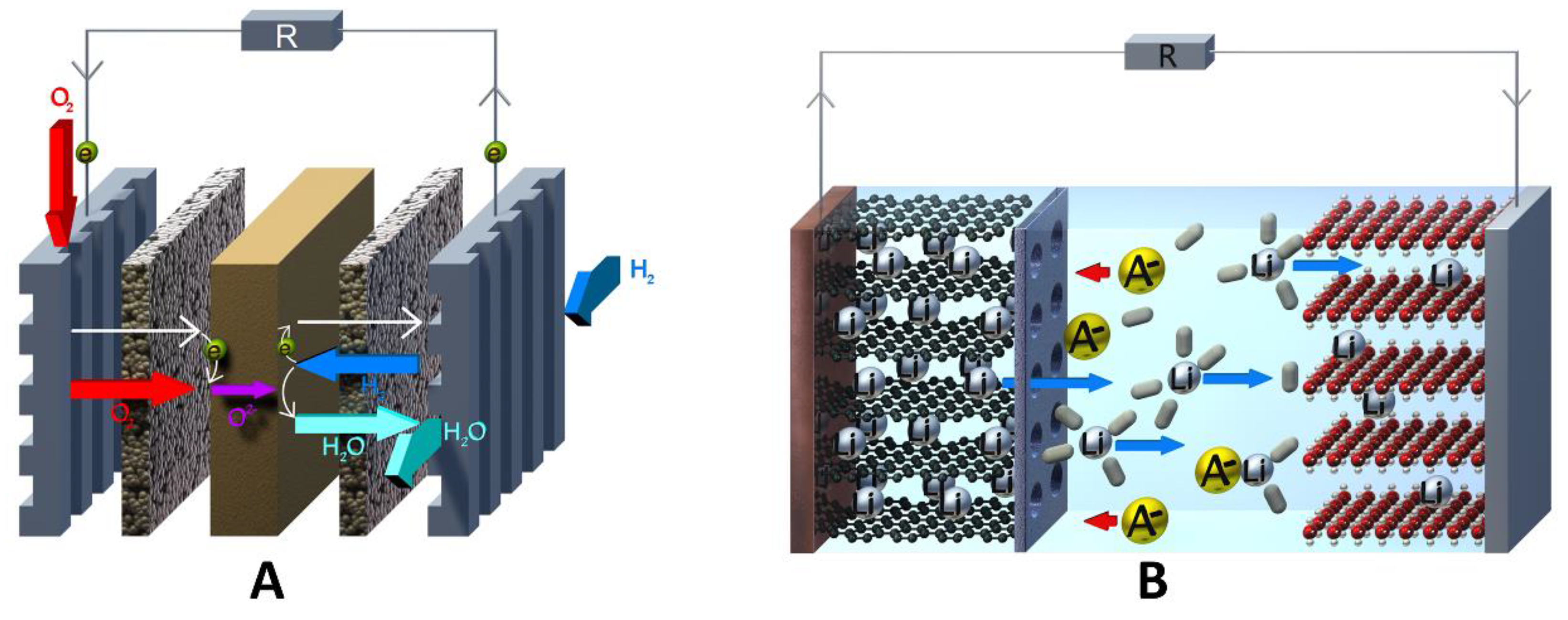
Due to the complex diversity of redox-flow cells with respect to their chemistries, and their different setups, it is difficult to categorize and relate them to and distinguish them from comparable energy storage devices (e.g., fuel cells; see Figure 1A) [1][2][3][4].

/media/item_content/202302/63eee4e6c099cbatteries-09-00004-g001.png
Figure 1. (A) Schematic of a hydrogen fuel cell with irreversible gas electrodes and (B) a lithium-ion battery (LIB).

1.1. General Definition of a Redox-Flow Cell

An energy storage device can be called a flow cell if:
(A) At least one reversible redox process takes place. Accordingly, a hydrogen fuel cell is not a redox-flow cell in the “classic” high-temperature solid-oxide fuel cell (SOFC) [5][6] or the “classic” low-temperature proton-exchange-membrane fuel cell (PEMFC) setups [7], since their conversion of hydrogen and oxygen to water is irreversible. However, there are exceptions: unitized reversible fuel cells (URFC) or reversible regenerative fuel cells (RFC) are capable of operating both as fuel cells and as electrolyzers, and could therefore be categorized as redox-flow cells of a special type. A more detailed description will be given in  section 1.2. (hybrid redox-flow cells) [8].
(B) One or more fluid transport systems to and from an external storage compartment have to be present in order to enable a separation between energy storage and energy conversion (charge and discharge of the cell). For example, a lithium-ion battery (see Figure 1B) is not a flow cell because all battery components (electrolyte, active material, current collector, separator) are confined in the cell housing without any interaction with an outside cell tank.
(C) At least one redox active species (RAS) has to be dissolved or dispersed in a liquid carrier.

1.2. General Cell Types

All-liquid redox-flow cell
The ALRFB cell [9] represents the most widely used and widespread cell design. This setup consists of a cell in which the anolyte and catholyte sides are either not separated (see single flow cell below), or physically separated from each other by one or more (up to three) separating membrane. On both sides of the membrane, all electrolyte components—charged and discharged redox-active species and supporting electrolytes—are completely dissolved in the selected solvent. The anolyte or catholyte sides can each have one or two separate storage tanks, depending on whether separation of the oxidized and reduced forms of anolyte and catholyte is necessary. However, since the redox species are completely dissolved €n the electrolyte, cross-contamination through the membrane separator can be a major challenge, and several strategies have been devised to overcome this problem [10][11][12][13][14].
Semi-solid redox-flow cell
A possible approach to minimize or even completely avoid the above-mentioned cross contamination problem is to use redox active particle dispersions within the anolyte and/or the catholyte formulation. In this case, the anolyte and the catholyte compartments are separated from each other by a well-defined size exclusion separator with significantly smaller pore diameters compared to the particles. This special setup is known as the SSRFB and can also be connected to one or two storage tanks for the anolyte and catholyte dispersion, respectively. This cell design allows easy adaptation of other energy storage technologies, e.g., the lithium-ion battery. Cathode materials such as lithium iron phosphate (LFP), LiCoO2 (LCO), and LiNi0.33Co0.33Mn0.33O2 (NMC111); and anode materials such as graphite, Li4Ti5O12 (LTO), and silicon (Li/Si) are used in combination with separators (e.g., Celgard© 2022) [15][16][17][18][19]. In addition to redox-active inorganic particle dispersions, low-molecular and polymer dispersions are also used in combination with, for example, dialysis membranes for size separation. Exemplary systems are polyhydroquinones and polyimides dispersed in water and 10-methylphenothiazines (MPT) and thioxanthones (THA) dispersed in acetonitrile [20][21].
Hybrid redox-flow cell
In contrast to the two full flow cell types mentioned above, HRFCs consist partly of a redox-flow cell and partly of a different energy storage technology. Additionally, they allow for easy adaptation, as explained for semi-solid redox-flow cells above. In general, two types are possible: solid reversible anode/cathode and reversible gas cathode/anode [22]. In the latter one, hydrogen is mainly used as an energy storage medium, and as mentioned at the beginning of this section, this type of hybrid redox-flow cell is also called a regenerative fuel cell (RFC). While hydrogen can be reversibly converted on the cathode side, inorganic and organic redox species are utilized in the anolyte compositions. Known examples of such anolyte compositions contain vanadium, iron, manganese, cerium, and bromine as inorganic redox species, or, e.g., 1,2-dihydrobenzoquinone-3,5-disulfonic acid as the organic redox species (BQDS [23][24][25][26][27][28]. Hydrogen-based RFCs enable very high energy densities. For example, Rubio-Garcia et al. were able to achieve an energy density of 45 W h L−1 in an H2/V hybrid redox-flow system [29].
Overall, HRFCs with gas cathode are a clever combination of the fuel cell and the redox flow concept, enabling the use of the high-energy storage medium hydrogen and gaseous energy storage media in general. However, this concept also bears major drawbacks: Some of these include the use of platinum, rhodium, or palladium as catalysts, which makes cell construction more expensive and more dependent on rare materials. Then, the conversion and storage of hydrogen poses a significant safety risk, especially for grid-connected large-scale stationary plants.
Single flow cell
In order to simplify a redox-flow cell to a minimum of components, membrane-less cell concepts with one common electrolyte have been developed, also known as single flow cells. The single flow cell concept can be realized if both redox-active species are insoluble in their charged states, deposited on current collectors, and afterwards provide electronic conductivity. The most investigated system is based on the nickel-hydroxide‖zinc alkaline flow battery (Scheme 1) [30][31][32].
Scheme 1. Redox reactions of the nickel−hydroxide‖zinc−alkaline−flow−system for the positive electrode in the anolyte compartment (above) and the negative electrode in the catholyte compartment (below).

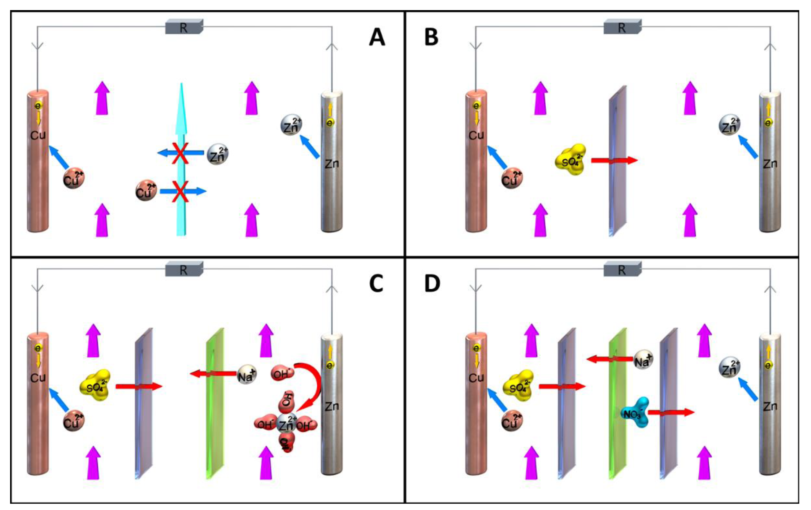
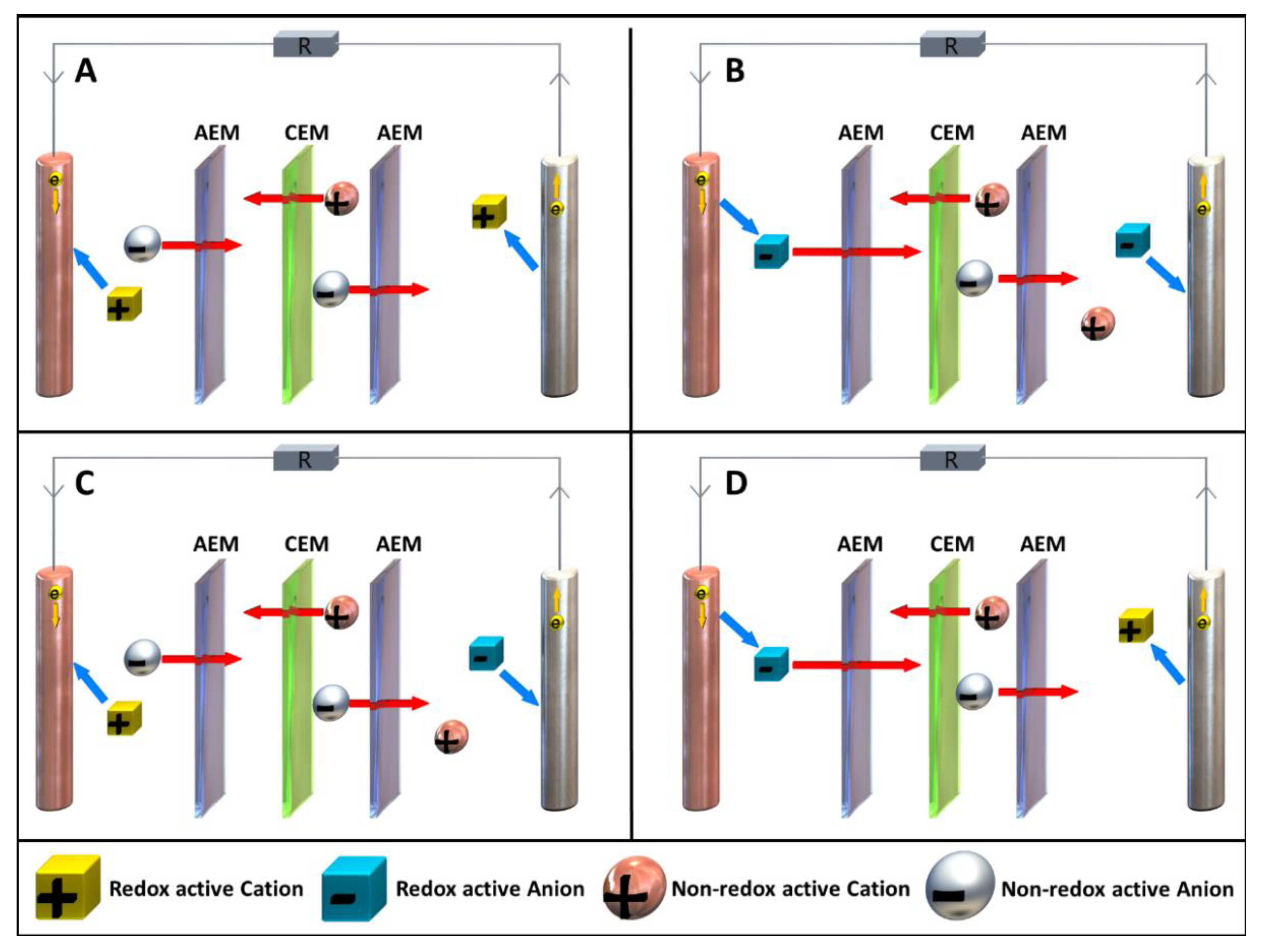
1.3. Cell Separation Techniques and Membrane Configurations

The above-mentioned flow cell types can be built without separation membranes and with one or more separation membrane, depending on the cell chemistry and cell geometry [33]. All possible separation techniques and membrane setups are displayed in Figure 2A–D using a “modified” Daniell-cell model.
/media/item_content/202302/63eee5b90b0e6batteries-09-00004-g004.png
Figure 2. Different numbers of ion exchange membranes and their functionality explained on a Danielle-cell-like model during discharge: (A) Setup with no membranes, realized by laminar flow, which prevents cross-stream diffusion, and therefore, intermixing of the anolyte and the catholyte. (B) Setup with one ion exchange membrane (here an anion exchange membrane (AEM)). This represents the most common setup. (C) Setup with two membranes. One AEM und one CEM. This setup is used when the electrolyte compositions of the anolyte and catholyte are different and the non-redox active counter-ions each have opposite charges. (D) Setup with three membranes with a symmetrical membrane arrangement (either AEM/CEM/AEM or CEM/AEM/CEM). This setup is used to highly suppress crossover of the RAS.
Zero membrane configuration
A “zero-membrane” configuration can be realized when either only one electrolyte composition is present, as in the single flow cell example, or when the geometric cell setup creates a laminar flow with cross-stream diffusion of the anolyte and catholyte; see Figure 2A [34]. To enable laminar flow in the cell, several conditions must be fulfilled:
The flow velocities of analyte and the catholyte must be as equal as possible. Furthermore, the flow rate must be slow and uniform. Point-like turbulent spots that always grow in size with downstream movement and finally merge to form a continuously turbulent region should be prevented [35]. Therefore, particle dispersions, as described for the semi-solid redox-flow type, are not suitable for a zero-membrane setup. Additionally, surfaces inside the cell and the pipe system should be smooth and without hard edges. This setup requires very precise cells, and also requires at all-times a constant flow through the cell to maintain separation by laminar flow.
Single-membrane configuration
In the single-membrane configuration, anolyte and catholyte are separated by one membrane (see Figure 2B), be it a size-exclusion or charge-exclusion membrane [33]. For cation exchange membranes (CEMs), the most known example is the all-vanadium redox-flow cell, where derivatives of polystyrene sulfonic acid cation exchange membranes are used [36][37][38].
For anion exchange membranes (AEMs), which are frequently used in AORFBs, the most common membranes are based on Nafion [39][40][41]. Next to that, micro- and meso-porous membranes consisting of polymer networks or metal organic frameworks (MOFs) [42] are often utilized as size-exclusion membranes for redox active polymer solutions and dispersions [43]. In the case of the above-mentioned Daniell-cell model, one RAS is reduced and plated to the electrode, whereas the other will be oxidized and dissolved. The common counterion (in this case the sulfate anion) migrates through the AEM to ensure charge balance in the anolyte and the catholyte compartment.
Dual-membrane configuration
In dual-membrane configuration, the anolyte and the catholyte are separated by two membranes, which in turn are separated by a third flow chamber; see Figure 2C [33]. The cell is designed with one anion exchange membrane and one cation exchange membrane. For the third chamber, a non-redox-active electrolyte is required, which has its own tank and pumping system.
This setup is used when the electrolyte compositions of the anolyte and catholyte are different and the non-redox active counter-ions each have opposite charges. To illustrate it using the Daniell cell setup, a tetrahydroxyzincate-based ([Zn(OH)4]2−) electrolyte is used on the cathode side, which contains Na+ as non-redox active counter-ion (Figure 2C).
Triple-membrane configuration
In the triple-membrane configuration, a symmetric membrane arrangement is used. The setup can either be AEM/CEM/AEM or CEM/AEM/CEM (e.g., arrangement AEM/CEM/AEM; see Figure 2D) [33]. A particularly outstanding feature of the two above-mentioned configurations is that they can be used universally. The anolyte and the catholyte can each consist of positively charged redox active ions and their negatively charged non-redox active counter-ions or vice versa. A combination of positively and negatively charged RAS is also possible. All combinations are illustrated in Figure 3A–D, exemplified by the triple membrane configuration AEM/CEM/AEM. A similar scheme can be constructed for the triple-membrane combination CEM/AEM/CEM. Another feature of the triple-membrane configuration is the ability to separate redox-pairs and their counter ions from each other. In the example of the Daniell cell model in Figure 2D, the sulfate anion and the nitrate anion also remain separate from each other.
Figure 3. Overview of all possible redox pair combinations, exemplified by the triple membrane configuration AEM/CEM/AEM, during the discharge process (anolyte on the right and catholyte on the left, respectively). The redox active ions are shown as cubes and non-redox active ions as spheres. (A): the RAS are positively charged in the anolyte and in the catholyte; (B): the RAS are negatively charged in the anolyte and in the catholyte; (C): the RAS within the anolyte is positively charged and that within the catholyte, negatively charged; (D): the RAS within the anolyte is negatively charged and within the catholyte, positively charged.

1.4. Summary

A variety of cell setups and special configurations are possible, as shown previously. The three most important factors are:
  • Type and number of membranes.
  • The nature, geometry, and surface area of the electrodes.
  • Geometry of the cell body, which strongly affects the electrolyte flow.
The setup is largely related to the choice of anolyte and catholyte composition. Polarity, number of phases, aggregate state of individual phases to each other, solvents, conducting salts, and the nature of the RAS used.

2. Electrolytes and Electrochemical Behavior

2.1. Introduction

Over the past decade, many studies have been dedicated to overcoming the drawbacks of conventional metal-based redox-flow systems by employing all-organic substrates as an inexpensive, safe, and sustainable alternative [44]. A transfer to non-aqueous solvents enables widening of the electrochemical window, and expanding operation to sub-zero temperatures and thus potentially higher energy densities.

Under strong consideration in general are polarity, with respect to the solubility of electrolytes and their charged states; viscosity, pertaining to the required circulation energy and mass transfer control from the electrode surfaces; and toxicity [45][46]. Another parameter one could take into consideration is the proficiency of the solvent to contribute to radical stabilization, which is related to the dipolarity/polarizability (not to be confused with polarity) of the electrolyte [47][48].

Out of these popular choices for solvent, acetonitrile is to date the most widely used, owing to its overall performance in these categories, and due to its relatively low corrosiveness and high physical resemblance to water. Nevertheless, though a fitting solvent system is essential for the durability of the RFB, ultimately, it is the electrolyte that makes up the final RFB characteristics within the solvent boundaries. Their chemical design involves several non-linearly related considerations for acquiring maximum energy density (e.g., synthetic costs, solubility of neutral and charged states, number of electrons passed, and cycling stability), making optimization a challenge, but the field as a whole open to significant advances. 

2.2. Catholytes

Next to its pioneering application in the first AORFB [49], TEMPO has been utilized to demonstrate other interesting conceptual advances in the field, most notably including bipolar application both upon stabilization of its reduction in ionic liquids [50] and by synthetic modification of the nitroxide radical (vide infra, “bipolar electrolytes”) [51][52][53], and it is a prospect for membrane-free batteries [54]. However, although membrane-free batteries could be a new avenue for redox flow, despite self-discharging arising from electron transfer at the interphase, to date there is no clear understanding of whether all-organic phases are feasible. The closest concept, having a liquid H2O separator between two organic phases, displayed volatility of the involved solvents and high Ohmic drops, causing major problems for this approach [55]. Staying with traditional AORFB setups instead—one of the quickest, and ultimately most developed, catholytes for AORFBs to follow was the dialkoxybenzene, owing to its modularity and chemical stability (Scheme 2).
Scheme 2. An overview of relevant considerations for electrolyte design, with the well-studied dialkoxybenzene catholyte as an example. Notably, molecular asymmetry was shown to be beneficial to the solubility, and thus energy density of the dissolved catholyte species [56].
Stabilization against radical side-reactions can also be efficiently tuned synthetically by steric shielding, as demonstrated by the frequent use of 2,5-dimethyl substituents.
This trend was also shown for 1,1′-dimethylferrocene by Cong and coworkers in their hybrid RFB [57]. The melting point of the subtly modified ferrocene was drastically lowered to 50 °C by the introduced asymmetry, and the solubility in turn greatly increased. Although not strictly organic, ferrocene has also been a popular choice for non-aqueous RFB applications. The small molecule is often considered amidst organics and plays a pivotal role in many redox-responsive systems next to serving as a standard reference on its own, not least for their robustness [58].
Another catholyte that has been widely investigated for its synthetic flexibility from the moment it was suggested as a possible overcharge protector, much like dialkoxybenzene, is phenothiazine [59][60]. Notably, although still with the aim of overcharge protection, Kaur et al. showed in 2016 that electron-withdrawing groups efficiently increase the oxidation potential, with per-fluorination of the phenothiazine, specifically, leading to upshifting by an impressive 0.8 V [61].
Theoretically, the energy density could increase significantly despite a lower solubility if the second redox event is made use of, as explored by Huang et al. in a phenothiazine AORFB with anthraquinone anolyte [62]. Though the cycling performance of the RFB was hampered by a limited chemical stability, it was shown that the anthraquinone anolyte rather than the phenothiazine catholyte was the major cause. In earlier work, Kowalski and coworkers showed that 3,7-dimethoxy substituents effectively stabilize the 2-electron oxidation through electron delocalization, albeit at the cost of solubility [63]
Although this separation is not smoothed out yet, an alternative synthetic strategy laid out in further work of the Odom group highlights a significant recent advance in electrolyte design. Upon introduction of a permanently charged tertiary ammonium group on the phenothiazine N-alkyl chain, Attanayake and coworkers demonstrated in very recent work that the corresponding conducting salt acts as a supporting electrolyte on its own, with ionic conductivity similar to that of TEA-TFSI [64]

2.3. Anolytes

Although phthalimides have developed further since Li and coworkers’ pioneering use of N-methylphthalimide as an AORFB anolyte [49], their poor solubility generally holds them back from competing with the state-of-the-art electrolytes. Most notably, however, Zhang et al. reported on an interesting strategy to circumvent this issue, by forming eutectics with LiTFSI and urea [65]. Although further work showed the possibility of creating bi redox-active eutectics [66], certain compositions in their earlier work yielded lower viscosities upon variation of the dilution with 1,2-dichloroethane. With a viscosity of ca. 130 mPa s at ca. 4 M of active species, ultimately posing a foreseeable issue for redox-flow circulation (versus water at 1 mPa s [67]), a viscosity of 15 mPa s upon further dilution to 1 M still demonstrates promise for this unusual approach.
The first more competitive structural follow-up to phthalimides as AORFB anolytes was a series of quinoxaline derivatives in the aforementioned work of Brushett et al. [68] Quinoxaline is especially interesting, considering its high solubility in propylene carbonate (ca. 7 M) and it undergoing a 2-electron transfer. Although the cyclic voltammetry of plain quinoxaline (R = H) shows poor reversibility, substitution with methyl groups α to the pyrazine nitrogens (R = CH3) resulted in both an improvement in reversibility and a further lowering of redox potentials owing to their electron donating ability. Methylation on the phenyl moiety with and without the α-methyls resulted in no significant changes, whereas introducing α-phenyl groups instead resulted in only a weak improvement over the core quinoxaline structure, suggesting that steric shielding of the redox-active site plays a role in the chemical reversibility here. 
Another structurally well-studied anolyte is anthraquinone. Although Huang and coworkers encountered stability issues regarding the second redox event of anthraquinone, the pairing with the phenothiazine catholyte led to a concept dual 2-electron AORFB [62]. Appending single and double 2-methoxyethoxy substituents to anthraquinone at various one-sided positions (1-, 2-, 1,2-, and 1,4-) increased their solubility and lowered their reduction potential.

2.4. Bipolar Electrolytes

A newer development in RFBs, due to their increasing complexity and compatibility requirements, is the creation of bipolar electrolytes, i.e., electrolytes containing a catholyte and an anolyte function simultaneously [69]. Although this generally requires a larger synthetic effort and imbues the active electrolyte with one to be solubilized component that is inactive at all times, the major advantage is that it eliminates capacity loss from cross-over [69][70]. An oxidized bipolar electrolyte traversing the membrane will regain its electron, reducing energy efficiency, but will then go on to take an active part in the charging process on the other side, and vice versa. One key requirement for favorable energy density in bipolar electrolytes is that the redox events are substantially separated. The presence of two successive redox events alone, such as in viologens, does not compete with state of the art when the OCP is only 0.5 V. Notably, conditions as subtle as the selected positive counterion in the supporting electrolyte can contribute significantly to the separation, as shown in an analogous pyridinium electrolyte [71], ultimately having a much more crucial impact on bipolar activity than on two-electron anolyte or catholyte storage. The poor compatibility of Li+ towards retaining redox potentials was noted in the abovementioned work of Zhang et al. on azobenzene also [72], although Li+-coordination with the charged anolyte state had a stabilizing effect. On the other hand, this compensatory effect was found to be absent for Wei and coworkers, with Li+, specifically out of a range of supporting electrolytes, having a substantial destabilizing effect on the fluorenone anolyte despite functioning well on the catholyte side [73].

2.5. Summary

Granted that the make-up of the RFB contains many complexly interrelated facets and that any given system may respond differently to minor changes, the trends observed above may contribute strongly to improving overall battery performance:
  • Acetonitrile is the solvent of choice, given its low viscosity and toxicity, and importantly, its polar nature, which generally contributes to solubilizing charged states also.
  • Generally, TFSI and TEA+ are preferred supporting ions. Alternatively, TBAPF6 is also often applied and performs well. Li+, notably, has exhibited some incompatibility issues in the anolyte compartment.
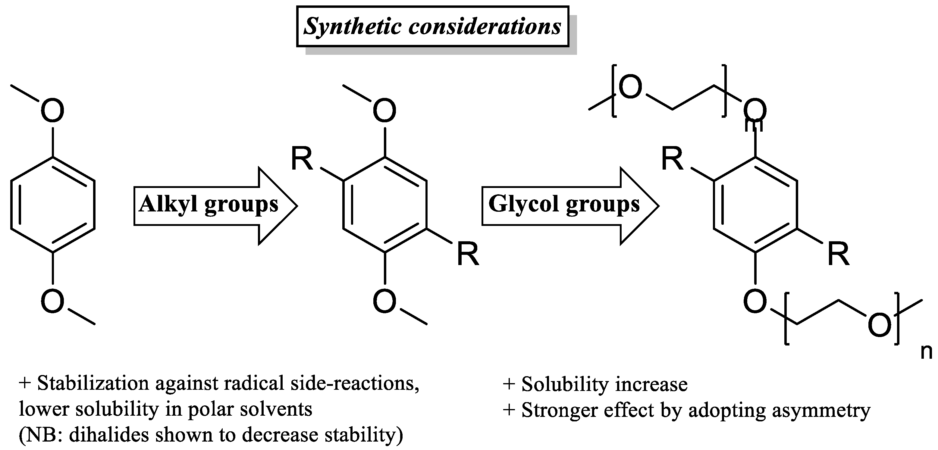
  • Electron-withdrawing substituents on catholytes and electron donating substituents on anolytes can slightly increase the system’s voltage, though a possible negative effect on stability may negate the gain in OCV.
  • Appending ethylene glycol (preferably asymmetrically) or tetraalkylammonium chains substantially increases the solubility in acetonitrile and to date seems to be the most efficient way to non-invasively increase energy density.
  • Imbuing both the catholyte and anolyte with permanent charge, for example, with tetraalkylammonium side-groups, enables the formation of electrolyte salts. This approach is especially promising, as it discards the need for a supporting electrolyte, since solely the counter-ion (e.g., TFSI) needs to traverse the anion exchange membrane, thereby simultaneously maximizing the concentration of active species and combating capacity decay from cross-over of electrolyte.

3. Introducing a RAS from Basic Lab-Scale Identification towards in-Flow RFB Measurements

3.1. Main RFB-Cell Components

3.1.1. Reference Electrode

The implementation of reference electrodes enables monitoring of either the anolyte or the catholyte compartment during galvanostatic battery charge and discharge [74][75][76][77]. With this, informative polarization techniques can be made, as they touch the limits of any redox electrolyte [78]. Ultimately, measuring an accurate cell voltage is highly important to guarantee a safe and reversible electrochemical reaction, as many efficiency-lowering processes are due to overpotential-induced decomposition side reactions. Therefore, the reference electrode has to be placed in the opposite half-cell of the current-applying electrode.

3.1.2. Current Collector, Flow Field, and Bipolar Plate

The differentiation within a half-cell between current collector, bipolar plate, and flow field can be misunderstood, since the respective component often fulfills multiple and mutually substitutive functions. The current collector works as an electrical connection to the circuit outside and reaction surface, and the flow field acts as a turbulent inducer to ensure good electrolyte distribution over the current collector’s entire surface [79]. The bipolar plate combines these properties, as it plays both a fluidic and an electrodynamic role, serving as a reaction surface and turbulence inducer [80]. For this, several different technical approaches have been developed, e.g., turbulent flow-through electrodes [81], “piece of pie” cell configuration [82], static mixer electrodes [83], and zero-gap cell designs [84][85]. However, the majority of research-scale RFB cell setups operate with the zero-gap approach. Here, all cell materials (i.e., conductive ground plates, carbon felts, and membrane) used are compressed by the cell to minimize distance-induced resistances. In a zero-gap configuration, conductive ground plates play a dual hydro- and electrodynamic role. The embedded flow frame guides redox electrolytes within an inner compartment of a flow cell, ultimately boosting the conversion rate and preventing an overpotential build-up over the entire electroactive surface [86]. Notably, this strategy has been subject to many computational studies over the past years [87][88][89]. On the other side, conductive plates act as current collectors, securing an electrical interfacing with external energy sources or loads [90]. To alter a diffusion regime, to extend an accessible electrochemically active area, and therefore, to ensure more effective mass conversion on the surface of current collector, a macro-porous 3D block of compressible and conductive material is normally introduced on top of the ground plate [91][92]. This configuration enables a considerably improved range of operational current densities supported by RFBs, although the range of accessible electrolyte flow rates is slightly decreased due to the pressure drop over an additional physical obstacle [93][94]. Typical choices for porous current collectors are carbon-based materials—thermally altered, chemically altered, or pristine versions of carbon/graphite felts [95][96][97] or carbon/graphite paper [98], and in some cases, well-defined reticulated vitreous carbon foams [99].

3.1.3. Separator

A separator, sometimes called “the heart of an RFB”, effectively separates the anolyte and the catholyte compartment electrolytes and serves to selectively permeate certain species of redox electrolytes [100][101][102]. Separators are conventionally classified referring to their transport mechanisms: (cation/anion/bipolar) selective-ion exchange membranes, microporous size-exclusion separators, ion-conductive glass ceramics, or an interface of immiscible redox electrolytes. In the context of RFBs, the term “membrane” refers to solid polymer ion-selective membranes, whereas a separator uses size exclusion [11][103]. Typical cation exchange membranes (CEM) consist of fluorocarbon- or hydrocarbon-based polymers with embedded terminal sulfonic groups, providing a rigid hydrophobic exterior and hydrophilic pore, where the cationic transport occurs. In turn, typical anion exchange membranes (AEM) incorporate terminal tetraalkylammonium groups. The special case, lastly, is bipolar exchange membranes, which are multilayer combinations of anion and cation conductive polymers.

3.2. Practical Difficulties of RAS Transversion and Their Theoretical Background

Introducing a new RAS into the area of redox flow brings about several new challenges. Compared to first fundamental investigations of the electrochemical behavior in a classical three-electrode setup, transferring to a RFB setup (i) changes electrode geometry and size, (ii) adds a separator between electrodes, and (iii) adds fluid-related mechanical effects, such as viscosity. The concurrent introduction of fluid mechanics during in-flow RFB cycling intensifies additional effects of mass transport and iR drop, leading to further changes in electron transfer kinetics during cycling. Simplified, these effects can be summarized in additional overpotentials in electrochemical measurements. As overpotentials have a huge impact on the reversibility, stability, and durability on long-term battery cycling, it is important to identify these. For this, an easy and fast technique such as cyclic voltammetry (CV) can be used.

3.2.1. Cell Setup and Processing Impacts on Mass Transport, Conversion, and Overpotential

In initial proof-of-concept electrochemical measurements, a classic three-electrode CV measurement should be performed to identify the RAS redox potential under “ideal” conditions. Additionally, this stage should be used to identify further important RAS specific characteristics, such as reversibility (basically peak-to-peak separation), diffusional coefficient D0, standard rate constant k0, or charge-transfer coefficient α [104][105].
When changing from proof-of-concept electrochemical to static RFB measurements, two main points change: the electrode surface size, and often also material, and the introduction of a separator between the working electrode and the counter and reference electrode. In terms of the electrode surface area for a classical disc macro-electrode, a linear semi-infinite diffusion model is assumed, where the peak-to-peak separation for reversible systems is equal to 2.218 RT/F [106]. However, if a macroscopically structured electrode material (e.g., carbon nanotubes, carbon foams, or graphite plates) is studied, the diffusion model changes. In summary, these enhancements in mass transport reduce the previously explained overpotential-induced peak-to-peak separation and further increase the peak intensities. Since for in-flow potentiodynamic measurements, the diffusive mass transport at the electrode surface is now superimposed by convection, the peak-limiting current of the CV measurement no longer is achieved by mass transport but by high SOC. The scan rate must be selected so low that the volume current ensures complete circulation of the electrolyte within 59 mV. As a higher SOC must be achieved for these measurements, both the stability of the RAS and the prevention of crossover of the RAS can be tested easily and quickly.

3.2.2. Membrane’s Impacts on Mass Transport, Conversion, and Overpotential

In order for the anolyte and catholyte compartment reactions to take place independently, a separator needs to be used. A semipermeable membrane, ideally, allows for passage of only the charge balancing ions, and not the RAS themselves [107]. To achieve this, one of two different mechanisms are applied: (i) charge exclusion or (ii) size exclusion [108][109]. In both cases, the separator is, in the electrochemical sense, an additional resistor in the system, as the crossing of charge-balancing species requires a certain activation energy [101]. For size exclusion, this mainly originates from the limited mass transport in the direct area of the membrane surface by Fickian’s law. For charge exclusion, specifically, coulombic repulsion additionally takes place, so that overall the introduced resistance is higher than that of a size exclusion separator [109][110]. For multiple separator setups, this resistance increases with every additional separator.

3.2.3. Viscosity’s Impacts on Mass Transport, Conversion, and Overpotential

In addition to the electrochemical changes described in the previous section, fluid mechanics play a large role in energy efficiency in-flow, largely effected by the porosity of the electrode and viscosity of the electrolyte solution [111][112]. A distinction can be made between the viscosity influence at the macroscopic level (I) and the atomic level (II). At the macroscopic level (I), viscosity acts like a force working against the flowing electrolyte, demanding more pump energy to maintain a constant volume flow with increasing viscosities [113]. Simplified, this can be described for a homogeneous Newtonian fluid in a straight pipe by the Hagen–poiseuille equation, with the volume flow being inversely proportional to the viscosity.

3.3. Summary

While moving towards in-flow RFB measurements, a phased approach of introducing the RAS to the RFB allows a stepwise identification of effects such as diffusional and convectional mass transport, Coulombic repulsion, and fluid mechanical changes, such as viscosity. This causes overpotentials and an iR drop. These effects are highly dependent on electrolyte composition and RFB setup and therefore, the optimum varies from RFB to RFB (electrolyte composition, type of membrane, flow rate, current density, type and geometry of electrode). For this, the step-by-step transferring sequence to better understand the transitioning effects and their intensity is emphasized: (1) proof-of-concept electrochemical measurements with classic CV three-electrode setup; (2) stationary RFB CV measurements; (3) in-flow RFB CV measurements. In the first part, the basic functionality of a RAS should be validated (i.e., redox potential, reversibility). In the second step, the impacts of RFB cell, electrode type, and membrane on the results obtained in the first part are evaluated. Finally, in the third step, the impact of volume flow is investigated, along with the minimization of cross-over. The results of this step-by-step sequence can then be used to define optimum charge-discharge parameters and cut-off criteria in order to obtain the most stable, safe, and durable RFB settings.

This entry is adapted from the peer-reviewed paper 10.3390/batteries9010004

References

  1. Xu, F.; Li, H.; Liu, Y.; Jing, Q. Advanced redox flow fuel cell using ferric chloride as main catalyst for complete conversion from carbohydrates to electricity. Sci. Rep. 2017, 7, 5142.
  2. Winter, M.; Brodd, R.J. What are batteries, fuel cells, and supercapacitors? Chem. Rev. 2004, 104, 4245–4269.
  3. Liu, W.; Gong, Y.; Tricker, A.; Wu, G.; Liu, C.; Chao, Z.; Deng, Y. Fundamental Study toward Improving the Performance of a High-Moisture Biomass-Fueled Redox Flow Fuel Cell. Ind. Eng. Chem. Res. 2020, 59, 4817–4828.
  4. Cho, K.T.; Tucker, M.C.; Weber, A.Z. A Review of Hydrogen/Halogen Flow Cells. Energy Technol. 2016, 4, 655–678.
  5. Lyu, Y.; Xie, J.; Wang, D.; Wang, J. Review of cell performance in solid oxide fuel cells. J. Mater. Sci. 2020, 55, 7184–7207.
  6. Brett, D.J.L.; Atkinson, A.; Brandon, N.P.; Skinner, S.J. Intermediate temperature solid oxide fuel cells. Chem. Soc. Rev. 2008, 37, 1568–1578.
  7. Wang, Y.; Ruiz Diaz, D.F.; Chen, K.S.; Wang, Z.; Adroher, X.C. Materials, technological status, and fundamentals of PEM fuel cells—A review. Mater. Today 2020, 32, 178–203.
  8. Mitlitsky, F.; Myers, B.; Weisberg, A.H.; Molter, T.M.; Smith, W.F. Reversible (unitised) PEM fuel cell devices. Fuel Cells Bull. 1999, 2, 6–11.
  9. Hamelet, S.; Tzedakis, T.; Leriche, J.-B.; Sailler, S.; Larcher, D.; Taberna, P.-L.; Simon, P.; Tarascon, J.-M. Non-Aqueous Li-Based Redox Flow Batteries. J. Electrochem. Soc. 2012, 159, A1360–A1367.
  10. Chakrabarti, M.H.; Dryfe, R.; Roberts, E. Evaluation of electrolytes for redox flow battery applications. Electrochim. Acta 2007, 52, 2189–2195.
  11. Shin, S.-H.; Yun, S.-H.; Moon, S.-H. A review of current developments in non-aqueous redox flow batteries: Characterization of their membranes for design perspective. RSC Adv. 2013, 3, 9095.
  12. Noh, C.; Shin, M.; Kwon, Y. A strategy for lowering cross-contamination of aqueous redox flow batteries using metal-ligand complexes as redox couple. J. Power Sources 2022, 520, 230810.
  13. Korshunov, A.; Milner, M.J.; Grünebaum, M.; Studer, A.; Winter, M.; Cekic-Laskovic, I. An oxo-verdazyl radical for a symmetrical non-aqueous redox flow battery. J. Mater. Chem. A 2020, 8, 22280–22291.
  14. Sikukuu Nambafu, G. Organic molecules as bifunctional electroactive materials for symmetric redox flow batteries: A mini review. Electrochem. Commun. 2021, 127, 107052.
  15. Duduta, M.; Ho, B.; Wood, V.C.; Limthongkul, P.; Brunini, V.E.; Carter, W.C.; Chiang, Y.-M. Semi-Solid Lithium Rechargeable Flow Battery. Adv. Energy Mater. 2011, 1, 511–516.
  16. Chen, H.; Lu, Y.-C. A High-Energy-Density Multiple Redox Semi-Solid-Liquid Flow Battery. Adv. Energy Mater. 2016, 6, 1502183.
  17. Biendicho, J.J.; Flox, C.; Sanz, L.; Morante, J.R. Static and Dynamic Studies on LiNi1/3 Co1/3 Mn1/3 O2 -Based Suspensions for Semi-Solid Flow Batteries. ChemSusChem 2016, 9, 1938–1944.
  18. Hamelet, S.; Larcher, D.; Dupont, L.; Tarascon, J.-M. Silicon-Based Non Aqueous Anolyte for Li Redox-Flow Batteries. J. Electrochem. Soc. 2013, 160, A516–A5202013.
  19. Guillon, O. (Ed.) Advanced Ceramics for Energy Conversion and Storage; Elsevier: Amsterdam, The Netherlands; Kidlington, UK; Oxford, UK; Cambridge, MA, USA, 2020; ISBN 978-0081027264.
  20. Yan, W.; Wang, C.; Tian, J.; Zhu, G.; Ma, L.; Wang, Y.; Chen, R.; Hu, Y.; Wang, L.; Chen, T.; et al. All-polymer particulate slurry batteries. Nat. Commun. 2019, 10, 2513.
  21. Xing, X.; Liu, Q.; Li, J.; Han, Z.; Wang, B.; Lemmon, J.P. A nonaqueous all organic semisolid flow battery. Chem. Commun. 2019, 55, 14214–14217.
  22. Soloveichik, G.L. Flow Batteries: Current Status and Trends. Chem. Rev. 2015, 115, 11533–11558.
  23. Yufit, V.; Hale, B.; Matian, M.; Mazur, P.; Brandon, N.P. Development of a Regenerative Hydrogen-Vanadium Fuel Cell for Energy Storage Applications. J. Electrochem. Soc. 2013, 160, A856–A861.
  24. Alon, M.; Blum, A.; Peled, E. Feasibility study of hydrogen/iron redox flow cell for grid-storage applications. J. Power Sources 2013, 240, 417–420.
  25. Cho, K.T.; Ridgway, P.; Weber, A.Z.; Haussener, S.; Battaglia, V.; Srinivasan, V. High Performance Hydrogen/Bromine Redox Flow Battery for Grid-Scale Energy Storage. J. Electrochem. Soc. 2012, 159, A1806–A1815.
  26. Rubio-Garcia, J.; Kucernak, A.; Zhao, D.; Li, D.; Fahy, K.; Yufit, V.; Brandon, N.; Gomez-Gonzalez, M. Hydrogen/manganese hybrid redox flow battery. J. Phys. Energy 2019, 1, 15006.
  27. Hewa Dewage, H.; Wu, B.; Tsoi, A.; Yufit, V.; Offer, G.; Brandon, N. A novel regenerative hydrogen cerium fuel cell for energy storage applications. J. Mater. Chem. A 2015, 3, 9446–9450.
  28. Rubio-Garcia, J.; Kucernak, A.; Parra-Puerto, A.; Liu, R.; Chakrabarti, B. Hydrogen/functionalized benzoquinone for a high-performance regenerative fuel cell as a potential large-scale energy storage platform. J. Mater. Chem. A 2020, 8, 3933–3941.
  29. Rubio-Garcia, J.; Cui, J.; Parra-Puerto, A.; Kucernak, A. Hydrogen/Vanadium Hybrid Redox Flow Battery with enhanced electrolyte concentration. Energy Storage Mater. 2020, 31, 1–10.
  30. Cheng, J.; Zhang, L.; Yang, Y.-S.; Wen, Y.-H.; Cao, G.-P.; Wang, X.-D. Preliminary study of single flow zinc–nickel battery. Electrochem. Commun. 2007, 9, 2639–2642.
  31. Im, Y.; Kim, J.; Park, K.S.; Cho, T.W.; Jeon, J.; Chung, K.; Eguchi, K.; Kang, M. Influence of small amount of Mg incorporated into hexagonal ZnO crystal on cell performance in membrane free Zinc–Nickel redox battery. J. Ind. Eng. Chem. 2018, 64, 318–327.
  32. Cheng, Y.; Zhang, H.; Lai, Q.; Li, X.; Zheng, Q.; Xi, X.; Ding, C. Effect of temperature on the performances and in situ polarization analysis of zinc–nickel single flow batteries. J. Power Sources 2014, 249, 435–439.
  33. Gu, S.; Gong, K.; Yan, E.Z.; Yan, Y. A multiple ion-exchange membrane design for redox flow batteries. Energy Environ. Sci. 2014, 7, 2986–2998.
  34. Bamgbopa, M.O.; Almheiri, S.; Sun, H. Prospects of recently developed membraneless cell designs for redox flow batteries. Renew. Sustain. Energy Rev. 2017, 70, 506–518.
  35. Von Doenhoff, A.E.; Braslow, A.L. The effect of distributed surface roughness on laminar flow. In Boundary Layer and Flow Control; Lachmann, G.V., Ed.; Elsevier Science: Amsterdam, The Netherlands, 1961; pp. 657–681. ISBN 9781483213231.
  36. Skyllas-Kazacos, M.; Rychcik, M.; Robins, R.G.; Fane, A.G.; Green, M.A. New All-Vanadium Redox Flow Cell. J. Electrochem. Soc. 1986, 133, 1057–1058.
  37. Skyllas-Kazacos, M.; Rychick, M.; Robins, R. All-Vanadium Redox Battery. U.S. Patent 4786567, 22 November 1988.
  38. Skyllas-Kazacos, M.; Grossmith, F. Efficient Vanadium Redox Flow Cell. J. Electrochem. Soc. 1987, 134, 2950–2953.
  39. Schulte, D.; Drillkens, J.; Schulte, B.; Sauer, D.U. Nafion Hybrid Membranes for Use in Vanadium Redox Flow Batteries. ECS Trans. 2010, 25, 247–255.
  40. Jiang, B.; Wu, L.; Yu, L.; Qiu, X.; Xi, J. A comparative study of Nafion series membranes for vanadium redox flow batteries. J. Membr. Sci. 2016, 510, 18–26.
  41. Maghsoudy, S.; Rahimi, M.; Dehkordi, A.M. Investigation on various types of ion-exchange membranes in vanadium redox flow batteries: Experiment and modeling. J. Energy Storage 2022, 54, 105347.
  42. Peng, S.; Zhang, L.; Zhang, C.; Ding, Y.; Guo, X.; He, G.; Yu, G. Gradient-Distributed Metal-Organic Framework-Based Porous Membranes for Nonaqueous Redox Flow Batteries. Adv. Energy Mater. 2018, 8, 1802533.
  43. Hendriks, K.H.; Robinson, S.G.; Braten, M.N.; Sevov, C.S.; Helms, B.A.; Sigman, M.S.; Minteer, S.D.; Sanford, M.S. High-Performance Oligomeric Catholytes for Effective Macromolecular Separation in Nonaqueous Redox Flow Batteries. ACS Cent. Sci. 2018, 4, 189–196.
  44. Chen, R. Redox flow batteries for energy storage: Recent advances in using organic active materials. Curr. Opin. Electrochem. 2020, 21, 40–45.
  45. Reichardt, C.; Welton, T. Solvents and Solvent Effects in Organic Chemistry, 4th ed.; Wiley-VCH: Weinheim, Germany, 2011; ISBN 9783527324736.
  46. Smallwood, I. Handbook of Organic Solvent Properties; Elsevier Science: Burlington, MA, USA, 1996; ISBN 0340645784.
  47. Jonsson, M.; Houmam, A.; Jocys, G.; Wayner, D.D.M. Solvent effects on redox properties of radical ions 1. J. Chem. Soc. Perkin Trans. 1999, 2, 425–430.
  48. Catalán, J. Toward a generalized treatment of the solvent effect based on four empirical scales: Dipolarity (SdP, a new scale), polarizability (SP), acidity (SA), and basicity (SB) of the medium. J. Phys. Chem. B 2009, 113, 5951–5960.
  49. Li, Z.; Li, S.; Liu, S.; Huang, K.; Fang, D.; Wang, F.; Peng, S. Electrochemical Properties of an All-Organic Redox Flow Battery Using 2,2,6,6-Tetramethyl-1-Piperidinyloxy and N-Methylphthalimide. Electrochem. Solid State Lett. 2011, 14, A171.
  50. Wylie, L.; Blesch, T.; Freeman, R.; Hatakeyama-Sato, K.; Oyaizu, K.; Yoshizawa-Fujita, M.; Izgorodina, E.I. Reversible Reduction of the TEMPO Radical: One Step Closer to an All-Organic Redox Flow Battery. ACS Sustain. Chem. Eng. 2020, 8, 17988–17996.
  51. Duan, W.; Vemuri, R.S.; Milshtein, J.D.; Laramie, S.; Dmello, R.D.; Huang, J.; Zhang, L.; Hu, D.; Vijayakumar, M.; Wang, W.; et al. A symmetric organic-based nonaqueous redox flow battery and its state of charge diagnostics by FTIR. J. Mater. Chem. A 2016, 4, 5448–5456.
  52. Hagemann, T.; Winsberg, J.; Häupler, B.; Janoschka, T.; Gruber, J.J.; Wild, A.; Schubert, U.S. A bipolar nitronyl nitroxide small molecule for an all-organic symmetric redox-flow battery. NPG Asia Mater. 2017, 9, e340.
  53. Charlton, G.D.; Barbon, S.M.; Gilroy, J.B.; Dyker, C.A. A bipolar verdazyl radical for a symmetric all-organic redox flow-type battery. J. Energy Chem. 2019, 34, 52–56.
  54. Navalpotro, P.; Sierra, N.; Trujillo, C.; Montes, I.; Palma, J.; Marcilla, R. Exploring the Versatility of Membrane-Free Battery Concept Using Different Combinations of Immiscible Redox Electrolytes. ACS Appl. Mater. Interfaces 2018, 10, 41246–41256.
  55. Peljo, P.; Bichon, M.; Girault, H.H. Ion transfer battery: Storing energy by transferring ions across liquid-liquid interfaces. Chem. Commun. 2016, 52, 9761–9764.
  56. Huang, J.; Cheng, L.; Assary, R.S.; Wang, P.; Xue, Z.; Burrell, A.K.; Curtiss, L.A.; Zhang, L. Liquid Catholyte Molecules for Nonaqueous Redox Flow Batteries. Adv. Energy Mater. 2015, 5, 1401782.
  57. Cong, G.; Zhou, Y.; Li, Z.; Lu, Y.-C. A Highly Concentrated Catholyte Enabled by a Low-Melting-Point Ferrocene Derivative. ACS Energy Lett. 2017, 2, 869–875.
  58. Astruc, D. Why is Ferrocene so Exceptional? Eur. J. Inorg. Chem. 2017, 2017, 6–29.
  59. Buhrmester, C.; Moshurchak, L.; Wang, R.L.; Dahn, J.R. Phenothiazine Molecules. J. Electrochem. Soc. 2006, 153, A288.
  60. Attanayake, N.H.; Kowalski, J.A.; Greco, K.V.; Casselman, M.D.; Milshtein, J.D.; Chapman, S.J.; Parkin, S.R.; Brushett, F.R.; Odom, S.A. Tailoring Two-Electron-Donating Phenothiazines to Enable High-Concentration Redox Electrolytes for Use in Nonaqueous Redox Flow Batteries. Chem. Mater. 2019, 31, 4353–4363.
  61. Kaur, A.P.; Casselman, M.D.; Elliott, C.F.; Parkin, S.R.; Risko, C.; Odom, S.A. Overcharge protection of lithium-ion batteries above 4 V with a perfluorinated phenothiazine derivative. J. Mater. Chem. A 2016, 4, 5410–5414.
  62. Huang, J.; Yang, Z.; Vijayakumar, M.; Duan, W.; Hollas, A.; Pan, B.; Wang, W.; Wei, X.; Zhang, L. A Two-Electron Storage Nonaqueous Organic Redox Flow Battery. Adv. Sustain. Syst. 2018, 2, 1700131.
  63. Kowalski, J.A.; Casselman, M.D.; Kaur, A.P.; Milshtein, J.D.; Elliott, C.F.; Modekrutti, S.; Attanayake, N.H.; Zhang, N.; Parkin, S.R.; Risko, C.; et al. A stable two-electron-donating phenothiazine for application in nonaqueous redox flow batteries. J. Mater. Chem. A 2017, 5, 24371–24379.
  64. Attanayake, N.H.; Liang, Z.; Wang, Y.; Kaur, A.P.; Parkin, S.R.; Mobley, J.K.; Ewoldt, R.H.; Landon, J.; Odom, S.A. Dual function organic active materials for nonaqueous redox flow batteries. Mater. Adv. 2021, 2, 1390–1401.
  65. Zhang, C.; Niu, Z.; Ding, Y.; Zhang, L.; Zhou, Y.; Guo, X.; Zhang, X.; Zhao, Y.; Yu, G. Highly Concentrated Phthalimide-Based Anolytes for Organic Redox Flow Batteries with Enhanced Reversibility. Chem 2018, 4, 2814–2825.
  66. Zhang, C.; Qian, Y.; Ding, Y.; Zhang, L.; Guo, X.; Zhao, Y.; Yu, G. Biredox Eutectic Electrolytes Derived from Organic Redox-Active Molecules: High-Energy Storage Systems. Angew. Chem. Int. Ed. Engl. 2019, 58, 7045–7050.
  67. Biso, M.; Mastragostino, M.; Montanino, M.; Passerini, S.; Soavi, F. Electropolymerization of poly(3-methylthiophene) in pyrrolidinium-based ionic liquids for hybrid supercapacitors. Electrochim. Acta 2008, 53, 7967–7971.
  68. Brushett, F.R.; Vaughey, J.T.; Jansen, A.N. An All-Organic Non-aqueous Lithium-Ion Redox Flow Battery. Adv. Energy Mater. 2012, 2, 1390–1396.
  69. Li, M.; Case, J.; Minteer, S.D. Bipolar Redox-Active Molecules in Non-Aqueous Organic Redox Flow Batteries: Status and Challenges. ChemElectroChem 2021, 8, 1215–1232.
  70. Potash, R.A.; McKone, J.R.; Conte, S.; Abruña, H.D. On the Benefits of a Symmetric Redox Flow Battery. J. Electrochem. Soc. 2016, 163, A338–A344.
  71. Hendriks, K.H.; Sevov, C.S.; Cook, M.E.; Sanford, M.S. Multielectron Cycling of a Low-Potential Anolyte in Alkali Metal Electrolytes for Nonaqueous Redox Flow Batteries. ACS Energy Lett. 2017, 2, 2430–2435.
  72. Zhang, L.; Qian, Y.; Feng, R.; Ding, Y.; Zu, X.; Zhang, C.; Guo, X.; Wang, W.; Yu, G. Reversible redox chemistry in azobenzene-based organic molecules for high-capacity and long-life nonaqueous redox flow batteries. Nat. Commun. 2020, 11, 3843.
  73. Wei, X.; Xu, W.; Huang, J.; Zhang, L.; Walter, E.; Lawrence, C.; Vijayakumar, M.; Henderson, W.A.; Liu, T.; Cosimbescu, L.; et al. Radical Compatibility with Nonaqueous Electrolytes and Its Impact on an All-Organic Redox Flow Battery. Angew. Chem. Int. Ed. Engl. 2015, 54, 8684–8687.
  74. Langner, J.; Melke, J.; Ehrenberg, H.; Roth, C. Determination of Overpotentials in All Vanadium Redox Flow Batteries. ECS Trans. 2014, 58, 1–7.
  75. Ventosa, E.; Skoumal, M.; Vázquez, F.J.; Flox, C.; Morante, J.R. Operando studies of all-vanadium flow batteries: Easy-to-make reference electrode based on silver–silver sulfate. J. Power Sources 2014, 271, 556–560.
  76. Cecchetti, M.; Casalegno, A.; Zago, M. Local potential measurement through reference electrodes in vanadium redox flow batteries: Evaluation of overpotentials and electrolytes imbalance. J. Power Sources 2018, 400, 218–224.
  77. Huang, Q.; Li, B.; Song, C.; Jiang, Z.; Platt, A.; Fatih, K.; Bock, C.; Jang, D.; Reed, D. In Situ Reliability Investigation of All-Vanadium Redox Flow Batteries by a Stable Reference Electrode. J. Electrochem. Soc. 2020, 167, 160541.
  78. Amini, K.; Pritzker, M.D. In situ polarization study of zinc–cerium redox flow batteries. J. Power Sources 2020, 471, 228463.
  79. Ke, X.; Prahl, J.M.; Alexander, J.I.D.; Wainright, J.S.; Zawodzinski, T.A.; Savinell, R.F. Rechargeable redox flow batteries: Flow fields, stacks and design considerations. Chem. Soc. Rev. 2018, 47, 8721–8743.
  80. Duan, Z.; Qu, Z.; Ren, Q.; Zhang, J. Review of Bipolar Plate in Redox Flow Batteries: Materials, Structures, and Manufacturing. Electrochem. Energy Rev. 2021, 4, 718–756.
  81. Ressel, S.; Laube, A.; Fischer, S.; Chica, A.; Flower, T.; Struckmann, T. Performance of a vanadium redox flow battery with tubular cell design. J. Power Sources 2017, 355, 199–205.
  82. Gurieff, N.; Keogh, D.F.; Baldry, M.; Timchenko, V.; Green, D.; Koskinen, I.; Menictas, C. Mass Transport Optimization for Redox Flow Battery Design. Appl. Sci. 2020, 10, 2801.
  83. Percin, K.; Rommerskirchen, A.; Sengpiel, R.; Gendel, Y.; Wessling, M. 3D-printed conductive static mixers enable all-vanadium redox flow battery using slurry electrodes. J. Power Sources 2018, 379, 228–233.
  84. Arenas, L.F.; Ponce de León, C.; Walsh, F.C. Engineering aspects of the design, construction and performance of modular redox flow batteries for energy storage. J. Energy Storage 2017, 11, 119–153.
  85. Ye, R.; Henkensmeier, D.; Yoon, S.J.; Huang, Z.; Kim, D.K.; Chang, Z.; Kim, S.; Chen, R. Redox Flow Batteries for Energy Storage: A Technology Review. J. Electrochem. Energy Convers. Storage 2018, 15.
  86. Arenas, L.F.; de León, C.P.; Walsh, F.C. Mass transport and active area of porous Pt/Ti electrodes for the Zn-Ce redox flow battery determined from limiting current measurements. Electrochim. Acta 2016, 221, 154–166.
  87. Aramendia, I.; Fernandez-Gamiz, U.; Martinez-San-Vicente, A.; Zulueta, E.; Lopez-Guede, J.M. Vanadium Redox Flow Batteries: A Review Oriented to Fluid-Dynamic Optimization. Energies 2021, 14, 176.
  88. Cervantes-Alcalá, R.; Miranda-Hernández, M. Flow distribution and mass transport analysis in cell geometries for redox flow batteries through computational fluid dynamics. J. Appl. Electrochem. 2018, 48, 1243–1254.
  89. Kumar, S.; Jayanti, S. Effect of flow field on the performance of an all-vanadium redox flow battery. J. Power Sources 2016, 307, 782–787.
  90. Houser, J.; Pezeshki, A.; Clement, J.T.; Aaron, D.; Mench, M.M. Architecture for improved mass transport and system performance in redox flow batteries. J. Power Sources 2017, 351, 96–105.
  91. Agar, E.; Dennison, C.R.; Knehr, K.W.; Kumbur, E.C. Identification of performance limiting electrode using asymmetric cell configuration in vanadium redox flow batteries. J. Power Sources 2013, 225, 89–94.
  92. Aguiló-Aguayo, N.; Drozdzik, T.; Bechtold, T. The role of electrode orientation to enhance mass transport in redox flow batteries. Electrochem. Commun. 2020, 111, 106650.
  93. Tang, A.; Bao, J.; Skyllas-Kazacos, M. Studies on pressure losses and flow rate optimization in vanadium redox flow battery. J. Power Sources 2014, 248, 154–162.
  94. Zhou, X.L.; Zhao, T.S.; An, L.; Zeng, Y.K.; Wei, L. Critical transport issues for improving the performance of aqueous redox flow batteries. J. Power Sources 2017, 339, 1–12.
  95. Zhang, X.; Wu, Q.; Lv, Y.; Li, Y.; Zhou, X. Binder-free carbon nano-network wrapped carbon felt with optimized heteroatom doping for vanadium redox flow batteries. J. Mater. Chem. A 2019, 7, 25132–25141.
  96. Cecchetti, M.; Messaggi, M.; Donazzi, A.; Facibeni, A.; Russo, V.; Casari, C.S.; Bassi, A.L.; Casalegno, A.; Zago, M. A combined morphological and electrochemical characterization of carbon electrodes in vanadium redox flow batteries: Insights into positive and negative electrode performance. Electrochim. Acta 2020, 329, 135143.
  97. Goulet, M.-A.; Habisch, A.; Kjeang, E. In Situ Enhancement of Flow-through Porous Electrodes with Carbon Nanotubes via Flowing Deposition. Electrochim. Acta 2016, 206, 36–44.
  98. Dennison, C.R.; Agar, E.; Akuzum, B.; Kumbur, E.C. Enhancing Mass Transport in Redox Flow Batteries by Tailoring Flow Field and Electrode Design. J. Electrochem. Soc. 2016, 163, A5163–A5169.
  99. Friedrich, J.M.; Ponce-de-León, C.; Reade, G.W.; Walsh, F.C. Reticulated vitreous carbon as an electrode material. J. Electroanal. Chem. 2004, 561, 203–217.
  100. Crothers, A.R.; Darling, R.M.; Kushner, D.I.; Perry, M.L.; Weber, A.Z. Theory of Multicomponent Phenomena in Cation-Exchange Membranes: Part III. Transport in Vanadium Redox-Flow-Battery Separators. J. Electrochem. Soc. 2020, 167, 13549.
  101. Darling, R.; Gallagher, K.; Xie, W.; Su, L.; Brushett, F. Transport Property Requirements for Flow Battery Separators. J. Electrochem. Soc. 2016, 163, A5029–A5040.
  102. You, D.; Zhang, H.; Sun, C.; Ma, X. Simulation of the self-discharge process in vanadium redox flow battery. J. Power Sources 2011, 196, 1578–1585.
  103. Schwenzer, B.; Zhang, J.; Kim, S.; Li, L.; Liu, J.; Yang, Z. Membrane development for vanadium redox flow batteries. ChemSusChem 2011, 4, 1388–1406.
  104. Wang, H.; Sayed, S.Y.; Luber, E.J.; Olsen, B.C.; Shirurkar, S.M.; Venkatakrishnan, S.; Tefashe, U.M.; Farquhar, A.K.; Smotkin, E.S.; McCreery, R.L.; et al. Redox Flow Batteries: How to Determine Electrochemical Kinetic Parameters. ACS Nano 2020, 14, 2575–2584.
  105. Li, M.; Odom, S.A.; Pancoast, A.R.; Robertson, L.A.; Vaid, T.P.; Agarwal, G.; Doan, H.A.; Wang, Y.; Suduwella, T.M.; Bheemireddy, S.R.; et al. Experimental Protocols for Studying Organic Non-aqueous Redox Flow Batteries. ACS Energy Lett. 2021, 6, 3932–3943.
  106. Streeter, I.; Wildgoose, G.G.; Shao, L.; Compton, R.G. Cyclic voltammetry on electrode surfaces covered with porous layers: An analysis of electron transfer kinetics at single-walled carbon nanotube modified electrodes. Sens. Actuators B Chem. 2008, 133, 462–466.
  107. Liang, Z.; Attanayake, N.H.; Greco, K.V.; Neyhouse, B.J.; Barton, J.L.; Kaur, A.P.; Eubanks, W.L.; Brushett, F.R.; Landon, J.; Odom, S.A. Comparison of Separators vs Membranes in Nonaqueous Redox Flow Battery Electrolytes Containing Small Molecule Active Materials. ACS Appl. Energy Mater. 2021, 4, 5443–5451.
  108. Machado, C.A.; Brown, G.O.; Yang, R.; Hopkins, T.E.; Pribyl, J.G.; Epps, T.H. Redox Flow Battery Membranes: Improving Battery Performance by Leveraging Structure–Property Relationships. ACS Energy Lett. 2021, 6, 158–176.
  109. Yuan, J.; Pan, Z.-Z.; Jin, Y.; Qiu, Q.; Zhang, C.; Zhao, Y.; Li, Y. Membranes in non-aqueous redox flow battery: A review. J. Power Sources 2021, 500, 229983.
  110. Chai, J.; Lashgari, A.; Wang, X.; Williams, C.K.; Jiang, J. All-PEGylated redox-active metal-free organic molecules in non-aqueous redox flow battery. J. Mater. Chem. A 2020, 8, 15715–15724.
  111. Barton, J.L.; Milshtein, J.D.; Hinricher, J.J.; Brushett, F.R. Quantifying the impact of viscosity on mass-transfer coefficients in redox flow batteries. J. Power Sources 2018, 399, 133–143.
  112. Barton, J.L.; Milshtein, J.D.; Brushett, F.R. Impact of Electrolyte Viscosity on Redox Flow Battery Performance. Meet. Abstr. 2017, MA2017-02, 560.
  113. Song, Y.; Li, X.; Yan, C.; Tang, A. Unraveling the viscosity impact on volumetric transfer in redox flow batteries. J. Power Sources 2020, 456, 228004.
More
This entry is offline, you can click here to edit this entry!