This research aims to modify the machining properties for carbide cutting tool by stabilizing zirconia coating on the substrate through sol-gel process to improve tribological and thermal properties of carbide insert that achieved through chemical process
- Yttira, Sol-gel
Improvement Tribological Properties for Carbide Cutting Tool by Ceramic Coating Deposition
Shaimaa J. Kareem a , Wurood Asaad M. b ,Haydar Al-Ethari c
aDepartment of Ceramic and Building Materials Engineering, College of Materials Engineering, Babylon University, Iraq. Email: mat.shiamaa.jaber@uobabylon.edu.iq, b Department of Refrigeration and Air Conditioning Engineering Technologies, Al-Salam College, University Iraq, Email: Wurood.A.Midab@alsalam .edu.iq, cDepartment of Metallurgical Engineering, College of Materials Engineering,University of Babylon, Iraq. Email: dr.eng.alethari@uobabylon.edu.iq
ABSTRACT:
Coating by sol-gel deposition to modify tribological properties of K10 carbide cutting insert was performed. Triethanolamine, a catalyst, and titanium tetra-isopropoxide (TTIP) were used to create the precursor titanium hydroxide, having a pH of 5.83. The cutting inserts were dipped coated for three seconds, and then dried for an hour at 355 degrees Celsius. The yttria stabilized zirconia hydroxide sol, which was produced by mixing zirconium n-propoxide (ZNP), ethanol, and HNO3 to prepare the YSZ coating film, was then applied on the inserts. The mixture was continually swirled while being ultrasonically sonicated in an ice bath (100 rpm).Yttrium (III) tris isopropoxide, isopropanol, and HNO3 were combined in a second solution, and the mixture was agitated for 15 minutes at 100 rpm to produce 8 and 15% mol of Y2O3. Then immerse a coated by titania inserts for 7 minutes in this solution. Following that, samples were calcined for three hours at 700°C after being air dried for 48 hours at room temperature. With different amounts of Y2O3 (8% and 15% mol), the film thickness for the carbide coated is 4 and 9 µm, respectively, at the same immersion time. The study examines the thermal and tribological characteristics of uncoated cutting inserts and the cutting inserts coated with TiO2/8YSZ and TiO2/15YSZ layers. According results , TiO2/8YSZ and TiO2/15YSZ had hardness values of 1151.6 HV and 1678.9 HV, respectively. The existence of phases arising from the coatings and substrate is confirmed by X-ray diffraction phase analysis. Titanium, zirconium, and yttrium are all present in the coatings under study, according to an EDS examination of their chemical makeup, along with oxygen. The TiO2/8YSZ and TiO2/15YSZ coated inserts have different scratch hardnesses, which are expressed in GPa. The value of a TiO2/8YSZ coated insert is 2.73 GPa, while the value of a TiO2/15YSZ coated insert is 22.98 GPa. In contrast to uncoated and TiO2/8YSZ coated inserts, TiO2/15YSZ coated inserts have lower each of coefficient of friction and rate of wear. TiO2/8YSZ coated insert has a lower thermal conductivity coefficient when compared to TiO2/15YSZ coated insert and carbide cutting insert, which have heat conductivity coefficients of 10.3, 14.1, and 41.8 W/m.K, respectively. The thermal expansion coefficients of the titania layer, 8YSZ layer, 15YSZ layer, and carbide cutting tool are (11*10-6, 3.66*10-6 , 3.546*10-6, 14*10-6 1/K).
Keywords: 8YSZ, 15YSZ, Sol_gel, Carbide cutting tool K10, Tribological properties
1.Introduction:
Ceramic coatings are layered materials with low thermal conductivity and strong thermal stability that are coated onto substrates in order to provide thermal protection in the most demanding high-temperature environment. [1]. Tool wear occurs in the machining application as a result of difficulties with wear mechanisms such chip variation, high pressure loads, and spring back. Additionally, many tool materials have limited thermal conductivity, which makes them unsuitable for machining. The high volume specific heat of these materials causes high cutting temperatures during machining . The selection of coating materials is constrained by fundamental properties such lack of phase shift, chemical inertness, high melting point, low thermal conductivity, and strong adherence to metallic substrate. In essence, very few materials can fulfill these requirements. Cemented tungsten carbide (WC-Co), which is made up of large volume fractions of tungsten carbide particles in a cobalt metal matrix, is one of the most widely used tool materials in a variety of manufacturing industries, including automotive, oil and gas drilling, geothermal energy exploration, mining, construction, and other applications where extreme wear resistance is required [2]. Four main properties are necessary in case of using carbide tools at high speeds. These are; wear resistance, toughness (breakage resistance), durability and hot hardness (chemical stability and high hardness). Advanced coating methods have an important part and aim to rise their durability to a high level. The coating improved many properties such as toughness, fracture strength, wear resistance, thermal shock resistance and hardness. Carbide tools may have one or more thin coating films applied to them [3]. Tools made of carbide are typically coated in one of two ways; physical vapor deposition (PVD) and chemical vapor deposition (CVD). Due of the high process temperature, the CVD technique may cause the tool's hardness to decrease. Due to lower precipitation temperatures in the PVD technique, hardness loss has no negative effects [4]. Typically, hard nitride and carbides such as TiN, CrN, TiCN, TiAlN, ZrN, TiZrN, and diamond like carbon (DLC) are used to coat carbide cutting tools. Usually, PVD techniques are used to produce such strong ceramic coatings on substrates [5]. Murat Durmaza and Fatih Yildizb [6] investigated the deposition of TiAlSiN, AlCrN, and TiAlN ceramic films on substrate by cathodic arc physical vapor deposition method, to enhance the wear characteristics of carbide material.
The steel workpiece surface that was milled using a carbide end mill covered with a TiAlN ceramic layer had the lowest surface roughness value following a high-speed milling procedure using uncoated and coated carbide tools. Rezende et al. [7] investigated the effects of multilayer cutting tool coatings on tribological situations. Cast iron was machined with tools made of K10 carbide tungsten. The tools were uncoated, multilayer coated with aluminum oxide, and coated with it (one layer of TiO2 and three layer of Al2O3 ). The multilayer coating fails between 30 and 40 N in a scratch test using a Rockwell indenter, while the Al2O3 coating fails at about 25 N. The multilayer coating adheres to the surface more effectively than the Al2O3 coating as a result.
The complex process of choosing a coating technology is heavily influenced by the component's capacity and financial restrictions. To properly balance the technical and financial viability of coating processes as well as the process' compatibility with the substrate, modern design procedures take the surface into consideration from the outset. Numerous coating techniques exist, including chemical vapor deposition, physical vapor deposition, thermal spray, laser cladding, and sol-gel deposition [8]. Wurood Asaad M et.al. [9] studied the best coating circumstances for ceramic oxide by sol-gel method on HSS cutting inserts.Wurood Asaad M et.al. [10] studying the effect of the multilayer coated insert and comparing it to an uncoated cutting HSS insert revealed the following results: tool life increased by 50%, friction coefficient decreased by 80%, thermal conductivity decreased by 37%, surface roughness for the work piece decreased by 38%, and temperature at failure decreased by 8–11%.
This research aims to modify the machining capabilities of the carbide insert by improvement its tribological and thermal properties by stabilizing zirconia using the sol-gel technique.
2.Experimental :
2.1. Carbide cutting insert
Tungsten cemented carbide insert (K10) were used in this study . All the inserts have identical geometry designated by the American National Standard Institute (AISI) as [TNMG 160408] [11]. The inserts feature a 13 mm side and a square cross section . The utilized carbide inserts' compositions are shown in Table (1).
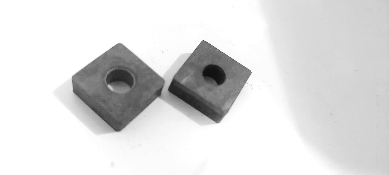
Fig.1: Carbide inserts used in the present work
Table (1): Chemical composition for carbide tool
|
Tool carbide |
Element |
Co |
W |
C |
Ti |
|
Percentage |
6 |
69 |
16 |
9 |
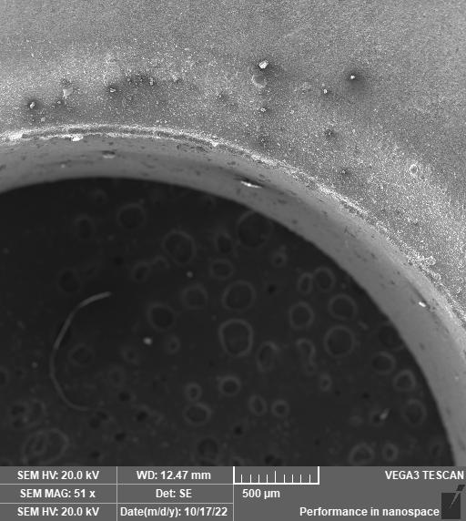
In accordance with ASTM B294-10 standard, use a load (150 kg) HRC with a tip (120) degree at 10 seconds. The hardness value's corresponding counterpart is (66.8 HRC). Following the fabrication of the cutting inserts, several emery paper grades (300, 400, 600, 800, 1000, 1500, and 2000) were used to grind the surface of the specimen to an adequate fineness, and it was then rinsed with water. The cutting insert was polished using a diamond paste with a grain size of (0.1-0.3)µm, this process continues until the sample surface becomes as mirror, and then it is washed by the water and alcohol and dried by hot air. Etching process was performed by immersion the sample for 3-6 min with freshly prepared mixture solution of K3Fe(CN)6 and sodium hydroxide then dry surfaces with acetone to indicate β (Co), α ( WC) phases. To indicate ℽ (WCx) carbide of cubic lattice phase, the samples was etched in solution of K3Fe(CN)6 and sodium hydroxide about 3-4 min then washed and dried species and etched in a solution mixture of equal volumes of concentration of hydrochloric acid and water about 10 sec, re etched about 20 sec in the first mixture [10, 12]. Then used Scanning Electron Microscope, the SEM morphology of the uncoated sample implant is depicted in Fig. 2.
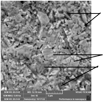
ℽ
α
β
Fig. 2 : Microstructure image for carbide cutting insert
2.2. Preparing of the coating materials ( TiO2/Zr2O3+Y2O3) by sol-gel route:
The surfaces of the cutting insert specimen were prepared by ordinary grinding starting at grade 220 and gradually increasing to grade 600. Grinding was done to ensure uniform roughness across all of the specimen surfaces. Before being dried in the air, the cutting inserts were first cleaned in an ultrasonic acetone bath for 15 minutes and then in methanol for 10 minutes. The built insert specimen received two distinct coating layers. These sorts consist of: titania TiO2 and yttria stabilized zirconia YSZ.
Titanium tetra-isopropoxide (TTIP) was used in the preparation of the Ti(OH)4 precursor together with 0.7N-hydrochloric acid (HCl) as a catalyst and isopropanol IP as a solvent. The typical composition had a molar ratio of TTIP: IP: 0.7NHCl= 1:26.5; 1.5. The mixture was stirred constantly for an additional hour at room temperature at 50 rpm. For the created Ti(OH)4 precursor's PH was tested and found to be 5.83. By dip coating, each cutting insert specimen immerse in a titanium hydroxide solution after 3 seconds of immersion time, at 10 cm/min speed, and after an hour of drying at 335°C.
To make YSZ, an initial solution was zirconium n-propoxide (ZNP), ethanol, and HNO3. The mixture was continually swirled while being ultrasonically sonicated in an ice bath (100 rpm). Then distilled water and acetic acid were added in a 3:1 weight ratio after 30 minutes. The molar ratios for ethanol, isopropanol, and water in these solutions were 10: 1, 6.6: 1, and 7: 1, respectively. Using 21.29 g of yttrium (III) tris isopropoxide, 4.8 ml of isopropanol, and 5 ml of HNO3, a second solution was prepared by mixing. The solution was kept stirred for 15 minutes at 100 rpm to produce an 8 mol% of Y2O 8YSZ). Similar solutions were prepared, but this time the amount of yttrium (III) tris isopropoxide was changed to produce a 15% mol of Y2O3 (15YSZ). After obtaining a pH of 4.43 of this solution , sample of titania coated was submerged in this solution (Y(OH)3 and Zr(OH)4 ) for 7 minutes. The samples were first dried in the air for 48 hours at ambient temperature, then calcinated for three hours at 700°C with a rate of 3 °C/min.
2.3. Characterization of the coating layers:
Ti(OH)4)
Using field emission scanning electron microscopy, the morphology and coating layer thickness were investigated. XRD analyses were used to determine the crystal phase, a scan range of (20-80) degrees, and a scan speed of (3 degrees per minute).
2.4. Wear and coefficient of friction test:
According to ASTMG9, this test was conducted using the pin-on-disc method. Type: MT4003 version 10, Software for data gathering and control was used for testing on friction and wear. A steel disc rotating at 300 rpm, a load of 10 N, and a sliding distance of 30 mm were used in the experiment, for intervals of 30 minutes. The pin was a ball pressed up against the whirling disc. A martensitic steel ball with a hardness of (990 HV) was used to conduct wear testing on the coated and untreated cutting inserts. The specimens were precisely and sensitively weighed before and after the test to assess the weight loss [13].
2.5. scratch test :
Indenter of silicon carbide was utilized to analyze the movement of the indenter along the coated, examined specimen's surface in the scratch test. To examine the coating's adherence to the insert, the test was run with a steadily increasing force. The following parameters were employed in the testing, which were conducted in accordance with ASTM D4541: With a load range of 5–50N, the penetrator travels over a distance of 4mm at a speed of 1mm/s [14].
2.6. Hardness test:
Rockwell hardness tester carbide cutting insert was conducted using a load of (150 kg) with a tip of (120)degree at 10sec. The load and displacement of the tip were recorded on the region of contact between the tip and the sample during an indent. Using a load of (500g) , the Vickers hardness test for the coating layer has been evaluated for (10 sec).
2.7. Measurement of the thermal conductivity and the thermal expansion Coefficients:
The Hot Disk Thermal Constants Analyzer is a tool for transient plane source (TPS) thermal characterization. The Hot Disk sensor was a heat source and a dynamic temperature sensor. An electrical current utilized for the measurement heated the sensor, which was then used to track the temperature rise over time. The experiment was performed on the Swedish-manufactured Hot-Disk TPS 500 model.2.8.
To measure the coefficient of thermal expansion, a dilatometer was used to measure how the substance's dimensions change in proportion to temperature. The sample is 13 mm long with a cross-sectional diameter of 2.5 mm.
3. Results and discussions
3.1. Characterization of the coating layers:
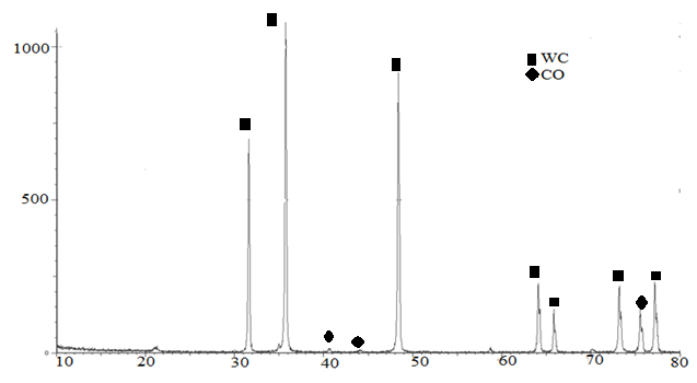
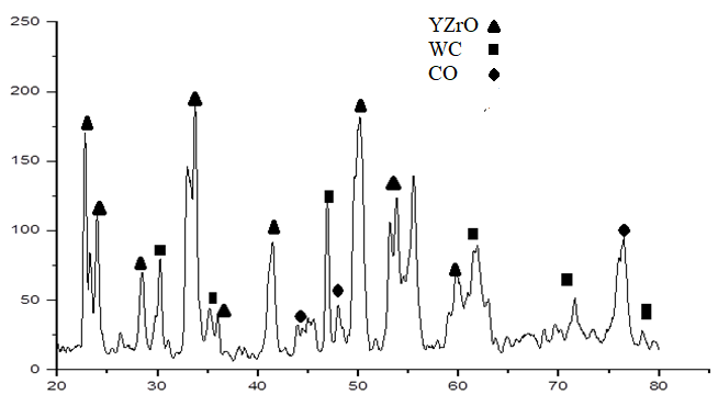
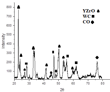
The carbide cutting insert ,8YSZ, 15YSZ layer were identified using X-ray diffraction (XRD) analysis at a rate of 3 degrees per minute. In comparison to the diffraction data cards (25-1047), (05-0727) the results for the WC and Co peaks were shown in Fig (3-a). Fig.( 3-b) depicts the 8YSZ layer's XRD. In order to compare the 8YSZ XRD pattern to the diffraction data card (00-082-1246), which displays six peaks of the Y0.2 Zr 0.8 O 1.9 phase and agrees with [Artras ALGA et al .al] [14]. According to Fig. (3-c), the Y0.2 Zr0.8 O1.9 phase's intensity increased with the addition of the 15YSZ layer. A shafted addition could be seen in the beak because the diameter ions for yttrium were equal to (1.04) A° and were larger than the radius ions for zirconium (0.74) Aº, so the rise in yttrium percentage caused the shaft to move to the left side. The stabilization of the cubic phase in sol-gel YSZ coating depends on temperature, heat treatment, and yttria concentration [15] . Fig.( 3-b) depicts the 8YSZ layer's XRD. In order to compare the 8YSZ XRD pattern to the diffraction data card (00-082-1246), which displays six peaks of the Y0.2 Zr 0.8 O 1.9 phase and agrees with [Artras ALGA et al .al] [14]. According to [Francisco J et. al], the stabilization of the cubic phase in sol-gel YSZ coating depends on temperature, heat treatment, and yttria concentration. [15] .
a
b
c
Fig.3. XRD Pattern of (a)carbide cutting tool, (b) 8YSZcoating, (c) 15 YZS coating
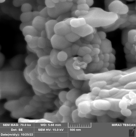
By varying the quantity of yttrium oxide, YSZ thin films were produced, and the surface morphology was examined using field scanning electron microscopy. The representative FESEM micrographs of YSZ thin film prepared by 8YSZ and 15YSZ are shown in Fig.4 For better understanding of the crystal growth process of the YSZ layers and quantitative description of the surface morphology, addition the influence of yttria concentration on the morphology of the end products. The crystallite size in nm decreased as the molar concentration of yttria increased from 8 to 15%; this indicates that the yttria content rise impeded crystal formation. This characteristic has been linked to the segregation of yttria at grain borders, which reduces mass transfer by surface diffusion and prevents the development of crystals that are consistent with [15] .

8YSZ
15YSZ

15YSZ
8YSZ
Fig.4 FESEM image of a multilayer coating (TiO2/ / YSZ) on carbide insert
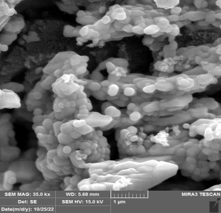
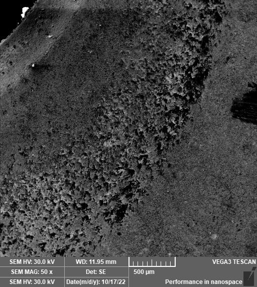
Fig. 5 depicts comparing between the morphology of 8YSZ layer and a like layer prepared by electrostatic spray on the carbide insert [Pavandatta M Jadhav et.al.] [16]. Can be noticed less agglomeration in particles through sol -gel method deposition, as shown Fig.(5-a) while more segregation can be found in Fig.(5-b).


a
b
Fig.5. ( a) FESEM image of coating 8YSZ on carbide insert by Sol_ gel, (b) FESEM image of 8YSZ thin film on carbide insert by Electrostatic Spray coating [16]
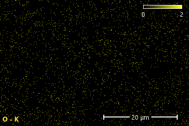
EDS mapping was carried out for the coatings TiO2/8YSZ layers and 15YSZ layer . Fig. 6-a, which depicts the spread of Ti, Zr, Y, O, W, and CO elements in region , summarizes the findings. These findings support the direct deposition of TiO2 on the substrate in the region of the titania layer, and the regions of Zr, Y, and O show the deposition of the Y Zr O phase. While using 15% yttira in stabilized zirconia can be shown in Fig. 6-b, the amount of yttira is growing.

a
|
|
|
|
|
|
|
|
|
|
|


b
|
|
|
|
|
|
|
|
|
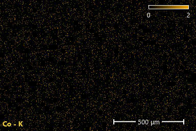
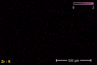
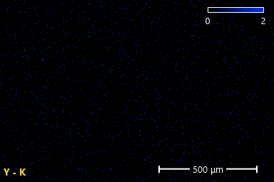
Fig. 6 EDS mapping of prepared sample : (a)TiO2 /8YSZ top coated insert,(b) 15YSZ top coated insert
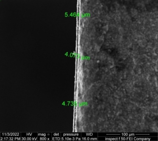
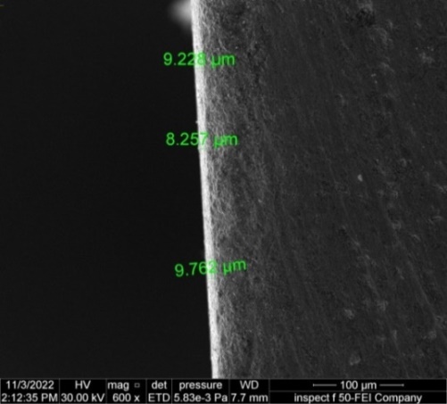
Fig. 7-a-b describe the effect of the amount of yttiria added to the hydroxide solution Zr(OH)4 mixture on the thickness of the coated layer. When the amount of yttitia added was raised from 8% to 15% mol during the same 10-second immersion period for the carbide sample in the coated solution, the layer thickness increased. This has to do with the size of yttrium ions and how those ions' size particles differ from those of zirconium ions. The radius of zirconium ions 0.74 A° while the ionic raduis of yttirum 1.02Aº.
b
a
Fig.7 (a): FESEM image of coating 8YSZ on carbide insert by Sol_ gel, (b) FESEM image of 15YSZ thin film on carbide insert
3.2. Physical test :
3.2.1. Thermal expansion coefficient
The bulk carbide insert thermal expansion coefficient is (14 *10-6 1/K) as shown as Fig. (8-a), while Fig. (8-b) shows that the average CTE of the titania layer is around (11*10-6 /K). This shows that the titania coating significantly minimizes the physical characteristics mismatch between the carbide insert and the applied ceramic coating. The results confirm earlier research that the Co content has a significant impact on the CTE of WC-Co composites but that the coefficient is not unduly sensitive to variations in WC grain size. This incidence is probably being caused by Cobalt's higher CTE than WC's [2]. When the amount of yttira increased from 8 to 15%mol, according to [18], the material's thermal properties changed. As a result, thermal conductivity increased and thermal expansion was reduced. This means that the thermal properties of zirconia in high-temperature applications are diminished as the yttira fraction is raised. Cutting tool ceramic coatings with 8YSZ and 15YSZ exhibit (3.66*10-6 and 3.546*10-6 1/K) thermal expansion, respectively that agree with X.Q. Cao. et.al [18].

a

b

c

d
Fig.8: Coefficient of thermal expansion, (a) carbide cutting tool , (b): forTiO2, (c) 8YSZ, (d) 15YSZ
3.2.2. Coefficient of thermal conductivity
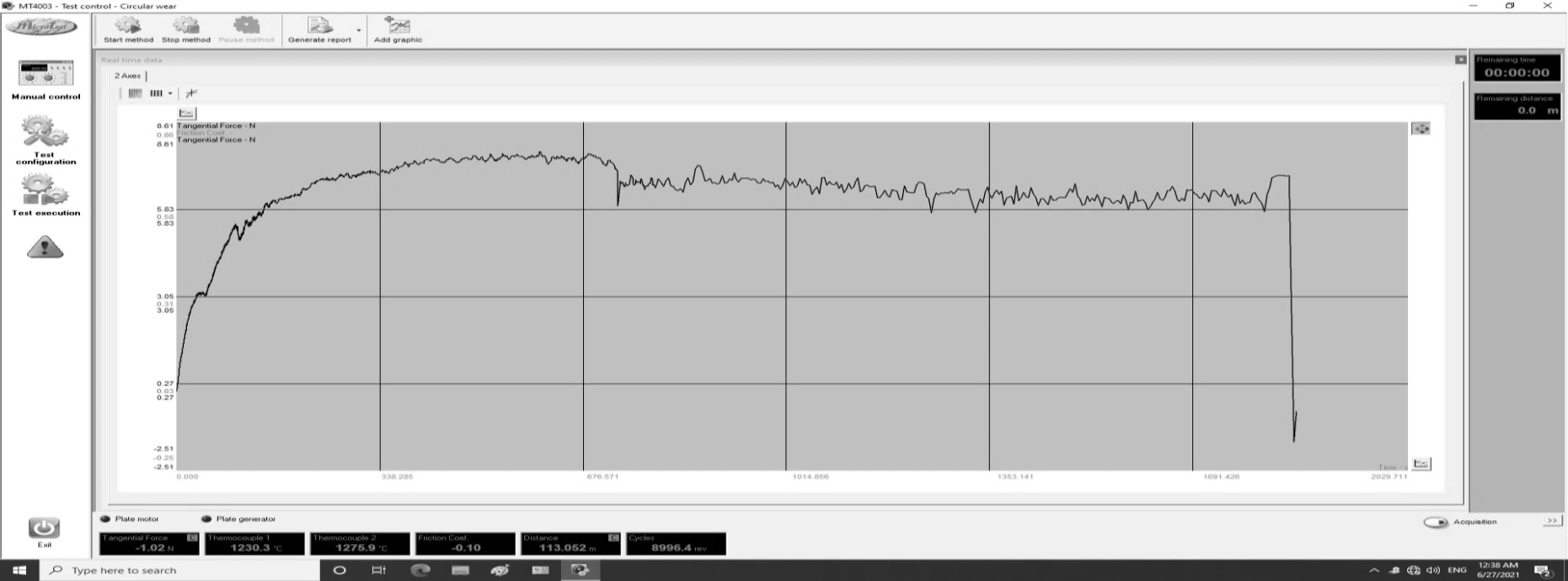
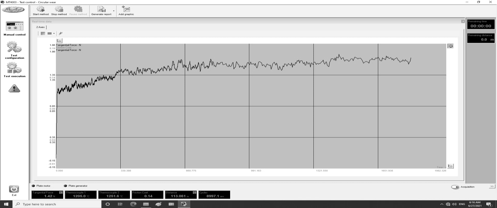
The thermal conductivity coefficient of the carbide insert used in this work is equal to (41.8 W/m.K), which is consistent with earlier research by Shijun Zhang [19]. Both the WC particle size and the cobalt content have a substantial impact on the thermal conductivity of WC-Co materials. In general, cobalt content and WC particle size can affect thermal conductivity [18]. Utilizing a transient plane source (TPS), the thermal conductivity of the ceramic coatings was measured. Typically, the bulk carbide insert heat conductivity is much higher than that of the ceramic coating. YSZ has a high thermal expansion coefficient, thermal shock resistance, and low thermal conductivity that affects the weight percentage of Y2O3 in the coated layer. The coated layer (TiO2/8YSZ) has the lowest thermal conductivity (measured at 27°C at room temperature (10.3W/m.k), while the TiO2/15YSZ coating layer's thermal conductivity at room temperature was(14.1 W/m. K), shows Fig 9. The nanostructured Yttria-Stabilized Zirconia (8 mol% Y2O3) 8YSZ was determined to be the most promising TBC for a variety of fundamental needs. Because it offers superior capabilities in high temperature applications, Yttria-Stabilized Zirconia (YSZ) nanostructured coatings provide thermal barrier coating (TBS) materials [2].
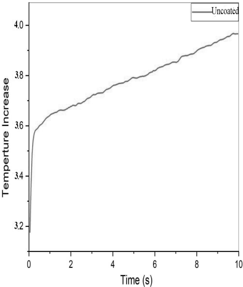
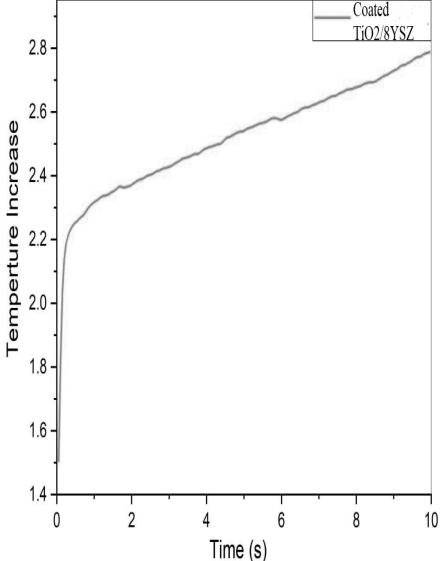
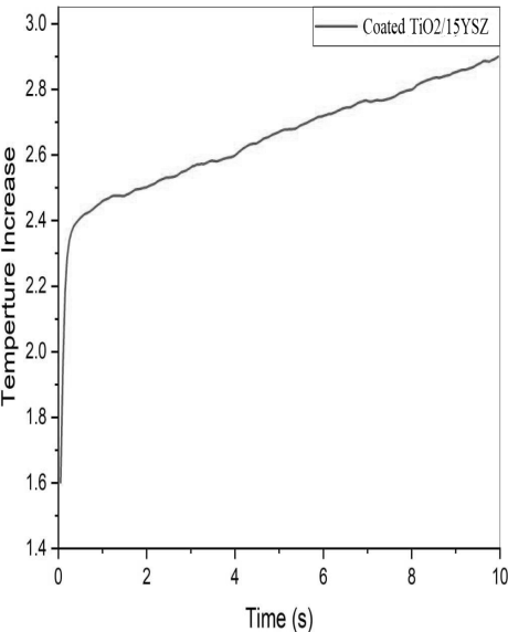 Fig.9: Transient graph of thermal conductivity, (a) uncoated insert, (b) TiO2/8YSZ, (C) TiO2/15YSZ
b
aa
c
3.3. Mechanical test
3.3.1. Hardness measurement
Micro hardness measurements reveal that the uncoated carbide implant has a hardness of 866 HV. The HV value increase with layer thickness increase of 8YSZ, 15YSZ, into 1152and 1679 HV, respectively. As shown Fig 10, micro indentation that the hardness of the surface increased with every deposited, reaching twice the hardness ,of carbide cutting tool at 15YSZ. These result are in agreement with [14].


a
b
c
Fig.10 Hardness test: (a) for uncoated insert , (b) for coated insert with TiO2/8 YSZ
, (c) for coated insert with TiO2/15 YSZ at 40 X
3.3.2. Scratch test:
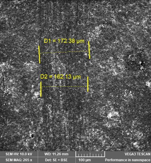
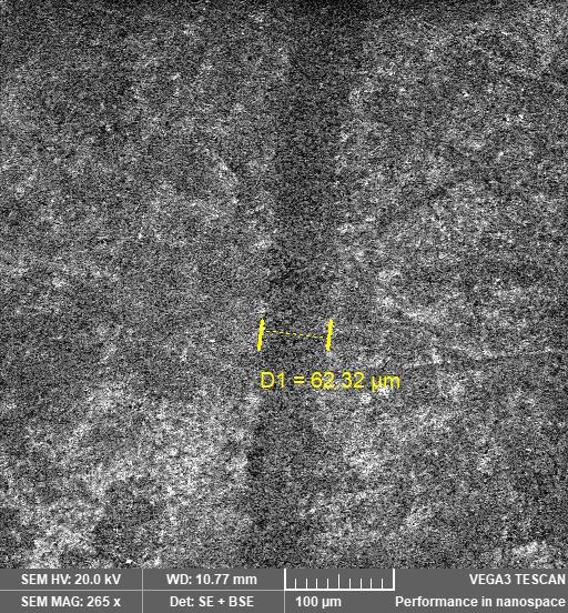
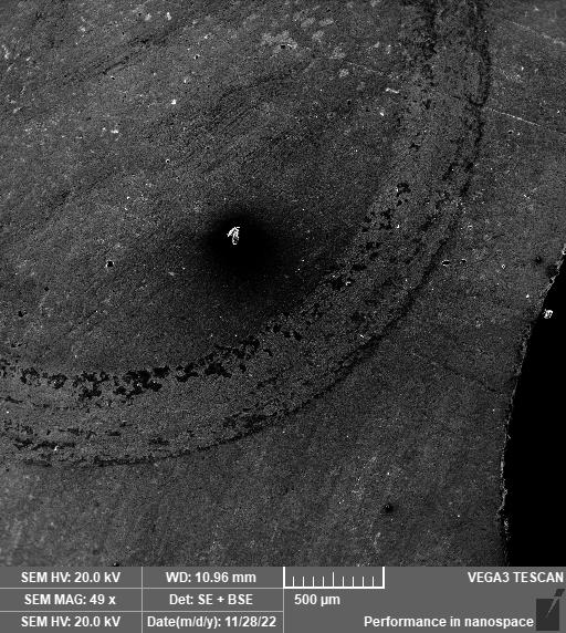
In comparison to the TiO2/15YSZ coating, which fails at 35 N and has a line of scratch width of 62.32µm, the TiO2/8YSZ coating fails in the scratch test at roughly 30 N. Francisco J et al. [15] discovered that compared to the 8YSZ coating, the 15YSZ coating (with a higher yttira concentration) appeared to have greater adherence. Fig.11 shows the scratch width for 8YSZ and 15YSZ coatings. The critical load was discovered by dividing the normal force at the time of coating removal by the values of the scratch hardness. Table 2 shows scratch-resistant comparison between 8YSZ/15YSZ layers.
b
a
Fig.11: (a) SEM of the scratched TiO2/ 8YSZ (b)SEM of the scratched TiO2/15 YSZ multilayers
Table (2): Mechanical qualities of the coating.
Coating layer Critical load Lc (N) Scratch hardness GPa
TiO2/8YSZ 30 2.73
TiO2/15YSZ 35 22.98
3.4.Wear test:
Fig. 12 a-b-c displays the behavior of the coefficient of friction for an uncoated and multilayer coated cutting insert (TiO2/YSZ) versus sliding distance. The initial friction coefficients of the uncoated carbide was (0.71) while the friction coefficient of carbide coated TiO2/8YSZ (0.31), and (0.17) with coated insert TiO2/15YSZ, which are slightly lower than those provided for uncoated carbide. This variation is related to the ceramic coatings' superior chemical inertness and lower heat conductivity. Pavandatta M. Jadhav et al description .'s of the effect of YSZ nano coating on the tungsten carbide tool material is the main focus of this investigation[16].
a
Carbide cutting tool

b
8YSZ Coated cutting tool
c
15 YSZ coated cutting tool
Fig. 12: Coefficient of friction versus sliding distance, (a) uncoated insert, (b) coated insert TiO2/8YSZ, (c) coated insert TiO2/15YSZ.
Tribological tests were conducted in two scenarios to evaluate the efficacy of dry sliding (Coated and Uncoated). The wear rate is measured in this investigation. Under a SEM microscope, the worn uncoated insert surfaces were examined to check for variations in wear behavior brought on by the presence of the TiO2/8YSZ nanoparticles. Severe wear evidenced by top surface disintegration, wear debris, and deep grooves in the sliding direction were the principal characteristics of an uncoated disc's worn surface. Fig. 13-a-b displays a deep and wide wear track, a surface roughness and mass change graph. Less affected sample under the same wear conditions with coated insert TiO2/15 YSZ from Fig. 13-c that related with amount of yttira to increase wear resistance.
The presence of ceramic material, which protects the contact surface from wear loss and to some extent resists plastic deformation, may be the cause of this. In contrast to YSZ coated insert, high adhesion and extensive plastic deformation between the opposing surfaces during sliding motion causes the change in mass induced by the same rotating speed to result in severe scratches on the contact surface [16].
c
a
b
Fig. 13: Wear track SEM micrographs of (a):uncoated inserts, (b): coated insert (8 YSZ), (c):coated insert (15 YSZ),
Our findings demonstrate that the wear rate for carbide cutting tools , TiO2/8YSZ and TiO2/15YSZ, respectively, 1.6 *10-4 , 0.72 *10-4 and 0.24*10-4 gm/cm. These values are comparable to those that have been reported for YSZ coated carbide cutting tool plasma sprayed [16].The wear rate of an uncoated insert is at its highest in Fig.14, but as the insert becomes YSZ coated, the wear rate is significantly decreased and continues to decline. Since coated inserts with TiO2/8YSZ and TiO2/15YSZ have higher ceramic layer hardness and better adherence to substrates than uncoated inserts, they essentially experience less wear.

Fig. 14 wear rate for each insert
4. Conclusion
According to the experimental findings, the length of immersion and the quantity of yttira had an impact on the coating layer's thickness, particle size, homogeneity, physical and triplogical properties when the carbide cutting tool was coated using the sol-gel method.
- When the amount of yttitia added was increased from 8% to 15% mol, the layer thickness grew from (4.5 into 9) µm. The crystallite size decreased and an aggregation could be noticed as yttira's molar content rose from 8 to 15%..
- Titania is a reduction in the differences in physical properties between the ceramic layer (YSZ) and the substrate , since the average TEC of the titania layer and the carbide insert (11, 14* 10-6 1/K) are nearly comparable.
- The TiO2/15YSZ layer on the substrate displayed a lower coefficient of friction and wear rate in comparison to TiO2/8YSZ. Additionally, its hardness and scratch resistance were higher than TiO2/8YSZ. In spite of TiO2/8YSZ, had excellent thermal properties comparing TiO2/15YSZ.
References
[1] . Rong-Guang Xu, Zhitong Chen, Peijian Chen, and Guangjian Peng, Special Issue: Mechanical Properties of Advanced Multifunctional Coatings. Coatings, (2022).
[2] Hongtao Wang, Tim Webb, Jonathan W. Bitler, Study of thermal expansion and thermal conductivity of cemented WC–Co composite, Int. Journal of Refractory Metals and Hard Materials(2014),.
[3] R. Suresh , S. Basavarajappa , V.N. Gaitonde , G.L. Samuel, Machinability Investigations On Hardened AISI 4340 Steel Using Coated Carbide Insert, Int. Journal Of Refractory Metals And Hard Materials 33 (2012) 75–86.
[4]. A. Bennett. Properties of thermal barrier coatings. Materials Science and Technology, 1986
[5]. W. Ronghua, J.V. John, N.M. Jesse, N.G. Michael, Aspects of plasma-enhanced magnetron-sputtered deposition of hard coatings on cutting tools, 2002. Surf. Coat. Technol. 158–159, 465–472.
[6]. Y. Murat Durmaza and Fatih Yildiz. 2018. The wear performance of carbide tools coated with TiAlSiN, AlCrN and TiAlN ceramic films in intelligent machining process. Ceramics International journal.
[7] Bruna Aparecida Rezende. Characterization of ceramics coatings processed by sol-gel for cutting tools, Anderson Junior dos Santos, and Marcelo Araujo Camara,Coatings, 2019, 9,557, pp. 1-12.
[8] Wurood Asaad M, Haydar Al-Ethari, Shaimaa J. Kareem, Surface Modification of Cutting Tool by Multilayer Coatings. AIP Proceeding, 2022.
[9] Wurood Asaad M, Haydar Al-Ethari and Shaimaa J. Kareem, Investigation on microstructure, morphology and properties of monolayer and multilayer coating T6-HSS by the sol-gel route, Advances in Materials and Processing Technologies, 2022, https://doi.org/10.1080/2374068X.2022.2129518.
[10] Wurood Asaad M, Haydar Al-Ethari and Shaimaa J. Kareem, 2022. Using Grey Relation Analysis to Improve Tool Life in Medium Carbon Steel Turning by Coating Multilayer HSS Insert, 2022 13th International Conference on Mechanical and Aerospace Engineering proceeding. 978-1-6654-7234-0/22/$31.00 ©2022 IEEE.
[11] ASTM Handbook , Iron and Metal Products, 1989, vol. 01.01
[12] Simran preet Singh Gill & Jagdev Singh & Harpreet Singh & Rupinder Singh, Metallurgical and mechanical characteristics of cryogenically treated tungsten carbide (WC–Co), Int J Adv Manuf Technol , 2012, pp. 119-131.
[13] T. Ramkumar, P. Narayanasamy, M. Selvakumar, and P. Balasundar,' Effect of B4C Reinforcement on the Dry Sliding Wear Behaviour of 138 Ti-6Al-4V/B4C Sintered Composites Using Response Surface Methodology', Arch. Metall. Mater. 2018, Vol. 63, No.3, PP: 1179-1200, DOI: 10.24425/123791.
[14] Artūras ŽALGA Brigita ABAKEVIČIENĖ, Aleksej ŽARKOV, Aldona BEGANSKIENĖ , Sigitas TAMULEVIČIUS,On the Properties of Yttria-Stabilized Zirconia Thin Films Prepared by Sol-Gel Method, MATERIALS SCIENCE. 2011, Vol. 17 No.2.
[15] Francisco J. Cano, Orlando Castilleja-Escobedo, L. J. Espinoza-Pérez, Reynosa-Martínez, and Eddie Lopez-Honorato, Effect of Deposition Conditions on Phase Content and Mechanical Properties of Yttria-Stabilized Zirconia Thin Films Deposited by Sol-Gel/Dip-Coating, Journal of Nanomaterials, 2021
[16] Pavandatta M Jadhav and Narala Suresh Kumar Reddy. Wear behavior of carbide tool coated with yttria-stabilized zirconia nano particles. IOP Conf. Series: Materials Science and Engineering. 2018
[17] R.S. Lima and B.R. Marple, Nanostructured YSZ thermal barrier coatings engineered, 2007
to counteract sintering effects, Materials Science and Engineering, pp. 182- 193.
[18] . X.Q. Cao, R. Vassen, D. Stoever. Ceramic materials for thermal barrier coatings. Journal of the European Ceramic Society, 2004
[19] Shijun Zhang and Zhanqiang Liu, An analytical model for transient temperature distributions in coated carbide cutting tools, International Communications in Heat and Mass Transfer, 2008