The raster angle is a determining factor in the tensile and flexural fatigue performance of FFF prints [
20,
24,
37,
53,
55,
57,
59,
68]. It has been shown that the tensile strength of FFF prints improves by decreasing the raster angle [
22]. In an ideal condition where the rasters of each layer are perfectly aligned with the axis of the applied tensile force (raster angle of 0°), the highest tensile strength is achieved [
70,
71,
72]. In the case of flexural and compressive loading, the highest static strength corresponds with grid patterns [
54] and perpendicular arrangement [
73], respectively.
Despite the static strength, the fatigue strength of FFF prints does not follow a particular trend against the raster orientation for all materials. In PLA prints, the raster angle of 45° has produced the highest tensile and rotating bending fatigue strength, while for ABS prints, 0° has been the optimum raster angle. For PETG prints, the highest fatigue life at high and low tensile stresses is achieved in 0 and 45° raster orientations, respectively. Afrose et al. [
37] studied the tensile strength and tensile fatigue behaviour of PLA prints with different raster angles (0°, 45°, and 90°). They observed that 45° prints show the best fatigue performance among the studied specimens. Interestingly, while 0° prints had the highest UTS, they exhibited the lowest fatigue life. The highest tensile fatigue strength was also achieved for 45° PLA prints in the work of Letcher and Waytashek [
59]. The endurance limit of 45° prints was reported to be 10 MPa, followed by 5 and 0.5 MPa for 0° and 90° prints, respectively. Arbeiter et al. [
20] investigated the tensile fatigue behaviour of notched PLA prints produced with raster orientations of 0° and 90°. They observed no significant difference between the fatigue strength of the printed samples. The authors also concluded that due to implementing a high nozzle temperature (250 °C) and optimum printing parameters, layers were bonded perfectly, resulting in near-homogenous samples. Thus, the raster orientation did not affect the fatigue strength of the samples markedly. As reported in the literature, the optimum raster angle in ABS prints is 0°. By comparing the S–N curves published in [
55,
57,
58], it is evident that 0° prints possess the highest fatigue resistance, followed by 45° and 90° prints in descending order. Similarly, the flexural fatigue life of 0° ABS prints was higher than those of 90° counterparts in the works of Corbett et al. [
69] and He et al. [
35]. ABS prints produced in the 0° direction resisted around 96,500 fatigue cycles as compared to less than half (~40,700) for 90° prints [
35]. In another study, ABS prints at different raster orientations were subjected to cyclic tension for up to 10,000 cycles [
53]. Although Y-aligned (0°) prints performed slightly better than 45° and X-aligned (90°) prints, all samples exhibited relatively similar fatigue resistance. Only one study investigated the fatigue behaviour of PETG prints in which tensile PETG specimens were 3D-printed at 0, 45, and 90° raster angles and were subjected to sinusoidal tensile cycles [
60]. It was found that 0° prints perform best at high stress amplitudes, followed by grid (45/−45°) and 45° prints. At low stress amplitudes, 45° prints exhibited the highest fatigue life. It should be noted that the fatigue test was not repeated for each data point in the latter study, making it hard to justify the underlying mechanism of this behaviour. However, it can be said that in all cases, 0° and 45° prints have shown higher fatigue performance than other raster angles. In the latter study, transverse (90°) prints had the least performance among other specimens.
The effect of the raster angle on the rotating bending fatigue performance of FFF prints was studied by Azadi et. al. [
68]. PLA and ABS were 3D-printed in round shapes as per ISO-1143 in horizontal (0°) and vertical (90°) orientations. All specimens were subjected to sinusoidal bending stress using a Santam rotating bending fatigue device. The fatigue resistance of all prints was reported to be higher at a 0° raster angle compared to that of 90° prints [
68].
Although a particular value has not been reported as the optimum raster angle in the studies conducted so far, it can be said 0° and 45° prints perform better than 90° prints in both ABS and PLA prints when subjected to tensile and bending cyclic forces. The significance of the raster angle in compression and combined fatigue loading modes has not been investigated yet. However, it is expected that in compression, the perpendicular alignment of extruded filaments against the loading direction would result in better fatigue performance, as is the case in the static compressive strength of FFF prints. It is noteworthy to mention that the deformation mode plays a decisive role in this regard. In tension, the specimen is stretched; thus, the highest strength is achieved when the extruded filaments are aligned with the applied load. In contrast, parts tend to buckle under compressive force, so an orthogonal arrangement in which the extruded filaments are perpendicular to the applied load gives the highest compressive strength [
73].
2. Infill Pattern
The pattern in which the filaments are deposited in each layer is called the infill pattern. The infill pattern also determines the inner structure and thus the overall stiffness of the print [
74]. In a specified infill pattern, junctions of extruded filaments at each layer (interlayer) or between two successive layers (interlayer) are formed in a certain shape, acting as stress concentration zones [
39,
62]. These concentration zones make the joint areas susceptible to debonding and cracking [
75]. Stress concentration is a primary reason for the fatigue failure of metals and plastics caused by material or geometrical discontinuities. Due to the formation of air gaps and imperfect bonding between layers during the 3D printing process, the fatigue life of FFF prints can be 100 times lower than that of injection-moulded parts [
24]. Infill or hole patterns in FFF prints are another source of stress concentration and reduced fatigue life. Therefore, fatigue strength can be affected by the infill pattern by altering the specifications of the joint areas.
A comparison between the results reported in the literature shows that cross-over patterns (e.g., grid and honeycomb) produce samples with higher tensile and bending fatigue resistance compared to those produced with rectilinear/line patterns. For instance, in a study by Ziemian et al. [
57], the tensile fatigue resistance of the weakest grid pattern (0/−90) was higher than that of the strongest rectilinear pattern with a raster angle of 0°. In a study conducted on ABS prints, it was observed that the grid pattern (45/−45°) produced the highest tensile fatigue life among the other patterns, i.e., 0°, 45°, and 90° at the same normalized fatigue stress [
55]. Similar behaviour has been reported for the rotating bending fatigue of FFF prints. The effect of rectilinear and honeycomb infill patterns on the rotating bending fatigue strength of ABS and PLA–wood composite prints was studied in [
64,
67] and [
18], respectively. Round specimens were fabricated according to ASTM D7774 and were subjected to stress-controlled fatigue cycles. The infill patterns were so printed that the load was aligned with the carrying direction.
Among different grid patterns, some literature studies have suggested that 45/−45° grid patterns perform better than other configurations under pure tensile cycles. As reported by Jap et al. [
24], when subjected to the same tensile force, 45/−45° patterned ABS prints exhibited a higher fatigue life compared to their 0/90° counterparts. However, when normalized stress (applied stress divided by the ultimate tensile strength of the specimen) was considered, both patterns showed a similar fatigue strength. Given that the static strength of each part is different, the static strength (UTS) of each print can be taken into consideration when assessing fatigue strength. In fact, the UTS is the highest-possible fatigue stress that a part can withstand only for one cycle, representing the first point (corresponding to the N = 1) in the S–N curve. The remaining points can be normalized by this value so that the S–N curve is bounded from 0 to 1. This is done by dividing the fatigue stress by the UTS. Ezeh and Susmel [
76] compared the normalized fatigue strengths of PLA prints. It was concluded that the tensile fatigue performance of a print is highly correlated to its ultimate tensile strength. A similar result was reported by Ziemian et al. [
57], in which different patterns (0/−90°, 15/−75°, 30/−60°, 45/−45°) were used to 3D-print ABS tensile specimens. The best tensile fatigue performance was observed in (45/−45°) grid specimens, followed by 30/−60°, 15/−75°, and 0/−90° samples. Although the tensile and bending fatigue performance of different infill patterns have been studied in a decent number of studies, other patterns can be subjected to further investigations. Cross-over patterns, such as hexagonal, honeycomb, and gyroid, are of particular interest due to their excellent performance under static loading [
22,
77].
In contrast to the infill pattern, pore patterns are used to fabricate porous FFF prints. In other words, the hole pattern determines the shape and arrangement of the holes (void spaces), while the infill pattern denotes the pattern of solid (infill) sections, i.e., extruded filaments. Similar to the infill pattern, pore patterns can substantially affect the fatigue behaviour of prints. Baptist and Guedes [
38,
61] fabricated a series of cylindrical PLA prints with grid (0/90°) and hexagonal (0/60/120) hole patterns and studied their compressive fatigue properties. They observed that the grid (0/90°) pattern performed better than the hexagonal pattern in terms of the number of cycles to failure in similar loading conditions. In another study, cylindrical PLA specimens were 3D-printed with grid (0/90°), hexagonal (0/60/120), and concentric radial hole patterns and were subjected to sinusoidal compressive fatigue loads [
62]. The grid (0/90°) pattern exhibited the highest number of cycles to failure (4400 cycles), followed by hexagonal (3200 cycles) and radial concentric (2500 cycles) patterns. Gong et al. [
63] analyzed the compressive fatigue resistance of porous PLA prints produced in triangular and circular hole patterns. Both groups were 3D-printed with the same infill density (40%) and were subjected to static and compressive fatigue loading. While PLA prints with a triangular pattern possessed a higher compressive strength and elastic modulus, circular patterned specimens exhibited a higher fatigue performance due to less stress concentration. A similar result was achieved for elastomer lattices [
78].
Since the fatigue resistance of prints is greatly affected by the arrangement of the rasters against the loading direction, infill patterns may exhibit different influences in different loading conditions. To address this matter, the stress distribution, decay of hysteresis loops, and failure mechanism of certain infill patterns in different fatigue loads can be studied in future research.
3. Infill Density
The infill density refers to the ratio of the solid volume to the entire volume of print. the infill density not only affects the weight, cost, shrinkage, and dimensional accuracy of an FFF print but also has a substantial influence on the mechanical strength, stiffness, and fatigue strength of plastics [
38,
61,
79].
The effect of the infill density on the fatigue behaviour of FFF prints has been investigated in a limited number of studies. As mentioned by Ezeh et al. [
76], FFF prints with infill densities less than 100% behave like an intrinsically notched material, resulting in inferior fatigue resistance. In all previous reports, it has been shown that a higher infill density results in higher stiffness, higher mechanical strength, and higher fatigue resistance. Jerez-Mesa et al. [
66] observed that the infill density positively affects the rotating bending fatigue strength of PLA prints. In other studies, ABS [
64], PLA [
67], and PLA–wood composite [
18] specimens were 3D-printed at three different infill densities (25, 50, and 75%) and were subjected to rotating bending fatigue. The highest fatigue performance in each group was achieved at 75% infill density. A similar trend is also seen in compressive fatigue behaviour FFF prints. PLA prints with 50% and 30% porosity resisted compressive fatigue even after 3600 cycles, but 70% porous prints failed at much lower cycles [
38,
61].
Given that the overall stiffness of FFF prints is correlated with their infill density, the same effect is expected to be seen in all types of fatigue loading. However, the intensity and significance of this effect are yet to be examined. Further, in some applications, such as biomedical implants and bone scaffolds, infill densities should be kept at low values (around 10 to 40%) for better tissue growth and integration [
80]. Hence, a compromise between the infill density and fatigue strength of FFF prints should be held. This issue can be the subject of future research.
4. Layer Height
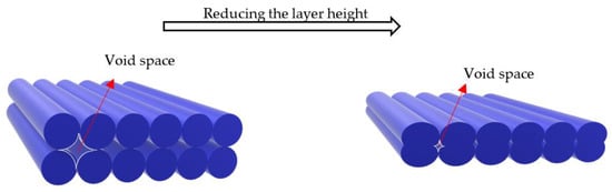
It has been shown that the layer height has different effects on the static and fatigue strength of FFF prints. In the case of static loading, reducing the layer height increases the mechanical strength through two mechanisms: First, it decreases the gaps between extruded filaments at adjacent layers, resulting in a less porous structure and higher stiffness. Second, the contact area between the extruded filaments increases, favouring the heat transmission between layers and better layer adhesion [
73]. Further, the cross-sectional shape of the void spaces between the deposited filaments changes with the layer height [
81], affecting the anisotropy and mechanical strength of the final product.
Figure 1 schematically illustrates the effect of the layer height on the porosity and shape of cavities in FFF prints.
Figure 1. Change in the porosity and cross-sectional shape of void spaces by changing the layer height.
In a study conducted on PLA prints with different layer heights, a 24.5% improvement was observed in the tensile strength of prints by reducing the layer height from 0.4 mm to 0.2 mm [
82]. The same effect was reported for the extrusion width when it increased [
83]. However, the influence of the extrusion width on the fatigue performance of FFF prints has not been studied yet.
In contrast to static loading, the influence of the layer height on the fatigue strength of FFF prints is the opposite, showing a direct correlation with fatigue life. The flexural fatigue strength of PLA [
84] and ABS [
35] specimens was found to be directly proportional to the layer height. However, the impact of the layer height on flexural fatigue strength has been reported to be low in comparison to other parameters. The results achieved for the layer heights of 0.1 and 0.3 mm showed a slight improvement in the flexural fatigue life of PLA prints produced with the higher layer height [
84]. This is while a lower layer height led to higher stiffness and elastic modulus in the latter study. There was also a 37% increase in the fatigue life of ABS prints when the layer height increased from 0.05 to 0.15 mm [
35].
The same effect can be seen when prints are subjected to rotating bending fatigue. In another study, the rotating bending fatigue performance of ABS prints at different layer heights was investigated according to ASTM D7774 [
64,
67]. It was found that a higher layer height leads to a higher number of cycles to failure. Jerez-Mesa et al. [
66] introduced layer height as the most influential factor in the rotating bending fatigue strength of PLA prints. Specimens with the honeycomb infill pattern, 75% density, 0.5 mm nozzle diameter, and 0.3 mm layer height sustained approximately 4700 cycles before failure. This was nearly 2.3 times that observed in specimens 3D-printed in the same condition but with a layer height of 0.1 mm. In a similar study conducted by Travieso-Rodriguez et al. [
18], the layer height was reported as the most influential factor on the rotating bending fatigue strength of PLA–wood composite FFF prints. The authors of this study examined three layer heights (0.2, 0.3, and 0.4 mm) and concluded that higher fatigue life is obtained when a higher layer height is implemented in the designs.
The contradicting effect of the layer height on the static and fatigue strength of FFF prints is believed to be due to their underlying failure mechanisms. Reducing the layer height increases the number of layers within the object, resulting in more stress concentration zones and reduced fatigue strength. However, it enhances static strength by reducing void spaces and improving the stiffness of the structure. Since studies in this area are scarce, there is a need to investigate the effect of the layer height on the performance of FFF prints under different fatigue loads.
5. Nozzle Diameter
The diameter of the nozzle has an influential impact on the quality and mechanical strength of FFF prints. It has been shown that the print quality and tensile strength of FFF prints improve when extruders with larger orifices are used [
85,
86,
87]. However, depending on the loading type and printed material, the nozzle diameter exhibits a different impact on the fatigue life of 3D-printed objects. For example, He and Khan [
35] reported that under flexural fatigue loading, the number of cycles to failure for ABS samples printed with a 0.8 mm nozzle was almost double the corresponding number for samples 3D-printed with a 0.4 mm nozzle. This was mainly because a higher nozzle diameter produces prints with lower void defects, resulting in higher stiffness and less stress concentration.
Similar studies for ABS [
64], PLA [
65,
66,
67], and PLA–wood composite [
18] prints under rotating bending fatigue demonstrated an uncertain relationship between the nozzle diameter and fatigue performance. Increasing the nozzle diameter from 0.3 to 0.5 led to an increase in the number of cycles to failure in PLA prints from around 1500 to 1800, 1200 to 2000, and 100 to 500 cycles in ABS, PLA, and PLA–wood composite prints, respectively. The same observation was reported for ABS prints in which the signal-to-noise ratio was reported to be 17.4% for the nozzle diameter, demonstrating the significant effect of this parameter on rotating bending fatigue strength [
64]. This is while an inverse correlation between the nozzle diameter and fatigue life was observed in the work of Dadashi and Azadi [
65]. These researchers printed PLA samples using three different nozzle diameters, i.e., 0.2, 0.4, and 0.6 mm, and studied their behaviour under rotating bending loads. A smaller nozzle size was shown to result in higher fatigue life. Although different printing conditions and materials can cause a discrepancy in results, further investigations are needed to fully understand the effect of the nozzle diameter on the fatigue behavior of FFF prints, as highlighted by Domingo-Espin et al. [
64]. Further, it should be noted that downsizing the nozzle orifice may cause mechanical strength degradation. It was reported that the nozzle diameter should be at least 1.5 times higher than the layer height for proper filament bonding [
64,
67], which was confirmed in another study by Travieso-Rodriguez et al. [
18].
6. Nozzle Temperature
The impact of the nozzle temperature on the fatigue strength of prints has only been investigated in one study. Azadi et al. [
65] printed PLA specimens with a nozzle temperature of 180 °C, 210 °C, and 240 °C and tested their performance under rotating bending fatigue. They observed that the highest fatigue strength was obtained for the samples produced at 180 °C. However, as reported by Arbeiter et al. [
20], the optimum temperature to obtain high-quality PLA prints was 250 °C. While this seems to be contrary to our understanding that a higher nozzle temperature results in efficient fusion of filaments and consequently stronger adhesion between them, it should be noted that it strongly depends on the filament’s material. Elevated temperatures may cause the physical and chemical degradation of the polymers. Since research studies in this area are scarce, further experiments are needed to fully understand the effect of the nozzle temperature on the fatigue response of FFF prints.
7. Printing Speed
Printing speed refers to the movement speed of the extruder. Higher printing speeds are desired when the printing time is of paramount significance. However, high printing speeds usually come at the cost of lower surface quality and reduced static strength [
88]. In a study by Corbett et al. [
69], the tensile fatigue behaviour of ABS prints at two different speeds (2000 and 4000 mm/min) was investigated. The authors reported that the feed rate is of significant influence, showing an inverse relation with fatigue life. That is, the samples printed at the lower printing speed (2000 mm/min) exhibited a higher fatigue life. However, printing polymers at low speeds causes the filaments to be in contact with the hot nozzle for a longer time, increasing the temperature within the filament. When exposed to elevated temperatures, thermal degradation occurs in polymers, resulting in degraded mechanical properties [
89]. This should be considered as a limitation for when the optimum printing speed is to be determined.
According to previous studies, the impact of the printing speed in the case of rotating bending fatigue is not as influential as shown in [
69]. ABS cylindrical samples were 3D-printed at different printing speeds (25, 30, and 35 mm/s), and their rotating bending fatigue behaviour was analyzed [
64,
67]. It was shown that the impact of the printing speed on fatigue life is insignificant. The same result was achieved for PLA prints [
66] and PLA–wood composite prints [
18] subjected to rotating bending fatigue. However, it is worth noting that the number of published results and the range of velocities studied in the literature are insufficient to draw a conclusion. Thus, further investigations should be conducted focusing on the bonding strength, the interfacial characteristics of extruded filaments’ junctions, and the fatigue behaviour of FFF prints when different printing speeds are used.
8. Build Orientation
Due to the layer-by-layer nature of 3D printing, FFF constructs possess a degree of anisotropy, depending on the building direction as well as the orientation of deposited filaments in each layer. Filaments act like fibres in a fibre-reinforced composite, exhibiting a directional anisotropy. Changing the build orientation alters the mesostructure of prints as well as the bonding chains between extruded filaments, resulting in different mechanical properties along the X, Y, and Z directions [
90,
91]. Zieman et al. [
58] investigated mechanical properties of ABS prints and concluded that the anisotropic behaviour of FFF prints under tensile fatigue loading originates from the directionality of the polymer molecules and air gaps within the specimens. In the work of Lee and Huang [
53], tensile specimens were 3D-printed in different building orientations. X, Y, and Z prints were 3D-printed so that the printer bed was perpendicular to the thickness, width, and length of the specimens, respectively. It was found that Y prints possessed a higher fatigue resistance at the same applied stresses. In a similar study by Fischer and Schöppner [
36], Y, X, and Z prints possessed the highest to the lowest UTS and tensile fatigue life, respectively. When subjected to a cyclic tensile load equalling 40% of the tensile strength, Y and X prints sustained around 8300 cycles, which was nearly double the cycles sustained by Z prints.
The flexural fatigue behaviour of polycarbonate (PC) prints is also reported to be significantly affected by the building orientation. In a study by Puigoriol-Forcada et al. [
14], PC rectangular plats with a length of 80 mm, a width of 10 mm, and a thickness of 4 mm were 3D-printed in X (80 × 10 × 4 mm
3), Y (4 × 80 × 10 mm
3), and Z (10 × 4 × 80 mm
3) orientations, with the first two dimensions representing the dimensions of the object on the print bed. It was shown that the Y prints possessed the longest fatigue life (at least 50% higher fatigue life than that of Z prints), followed by X and Z prints.
A noteworthy point in assessing the influence of the build orientation is the magnitude of the applied stress. The results achieved by Fischer and Schöppner [
36] and Puigoriol-Forcada et al. [
14] revealed that the difference between the fatigue life of different prints at different building orientations is notable at higher stresses but tends to decrease at low stresses. This highlights the influence of anisotropy at higher loads and demonstrates the importance of the build orientation when the FFF print is designed to work under high fatigue stresses.
This entry is adapted from the peer-reviewed paper 10.3390/app13020904