Fretting corrosion at the head–neck interface of modular hip implants entails regional inflammation and adverse local tissue reactions. Surface topography is one key factor which can influence the severity of this damage mechanism. The methodologies together with the assumptions and main findings from both the experimental and numerical studies are presented to evaluate the performance of the microgrooved junctions using two criteria as: stability and integrity; wear, corrosion, and material loss. Current research needs and possible future research directions for the microgrooved junctions are then identified and presented.
- microgrooves
- stability
- fretting corrosion
- hip implant
1. Introduction
Modularity at the head–neck junction of hip implants is popular as it enables surgeons to include patient-specific anatomical requirements in hip arthroplasty [1][2][3]. In addition, modularity enables surgeons to select materials for the components (head and trunnion) [4][5][6] with lower risks/costs in replacement surgeries [7][8]. However, the modularity is reported to be associated with mechanically assisted crevice corrosion (MACC) [9][10][11]. Under loading, the taper interface ends up with metallic ions/debris emitted from the interface [4][5][7]. The severity of this damage depends on the taper angle mismatch [12][13][14], geometrical dimensions [15][16], surface topography [17][18], the nature of the applied loads [19][20], and the assembly force [21][22][23]. The current understanding recommends a well-engaged contact as one solution for minimizing the damage at the junction interface [4][13][14][24].
Surface finish/roughness is one factor affecting the interface engagement [4]. The periodic pattern of microgrooves is classified with an amplitude and wavelength of more than 4 µm and 100 µm, respectively [25]. These microgrooves could decrease the fluid ingress into the gap of the junction as a result of toggling effects, thus reducing the corrosion. The presence of such microgrooves is believed to make up for for the influence of taper angle mismatch [26][27][28]. Although modern junctions are designed with microgrooves, research shows that there is a limited understanding of the influence from these microgrooves. Some studies confirm no significant role by these microgrooves in the interface damage [29][30] but some others report higher/lower interfacial damage for these junctions [26][27][28]. There is also disagreement on the influence of these microgrooves on strength [24][28]. In addition, variations in the geometry of microgrooves are evident in the junctions, even those produced by the same manufacturer [26][27][28].
The aim of this summary was to present the latest research findings of the influence of microgrooves on the performance of the head–neck junctions. Different approaches taken by various researchers together with their main findings are presented to provide a better picture of microgrooved junctions. The performance of the junctions is evaluated according to stability and integrity; and wear, corrosion, and material loss.
2. Taper Junctions of Hip Implants
2.1. Stability and Integrity
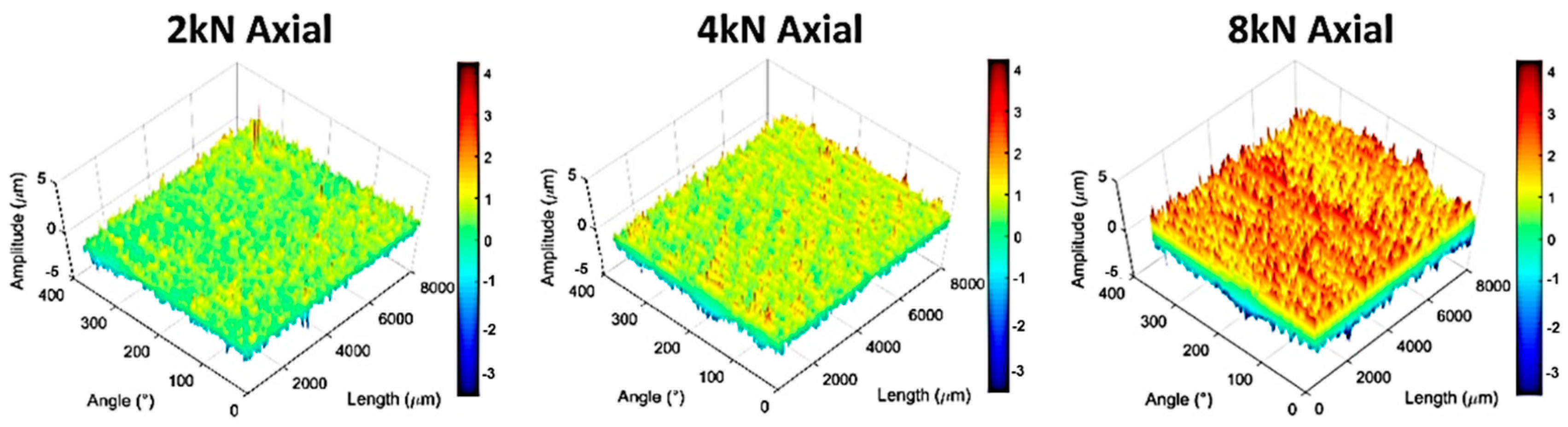
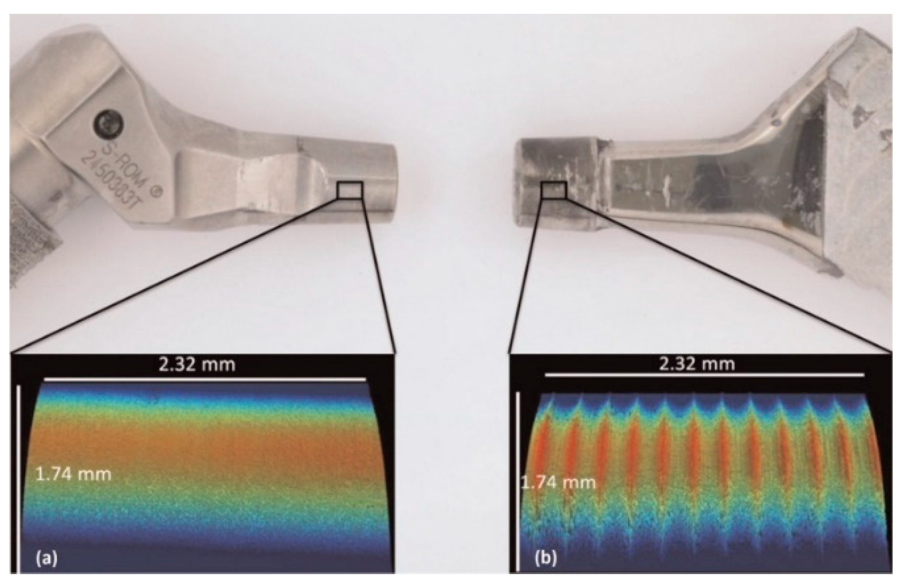
The stability of the taper junctions is compared using various metrics such as the contact situation, micromotion, etc [4][5]. There have been few studies with a focus on investigating the influence of microgrooves on the stability of taper junctions. In a study by Dransfield et al. [25], the contact situation was monitored for these junctions. The assembled junctions were dismantled using an Instron machine. Of all the test samples, the junction assembled with 8 kN at 10° antero-proximal showed maximal dismantling force. Global compression of the microgroove amplitudes increased with the assembly force (Figure 1).
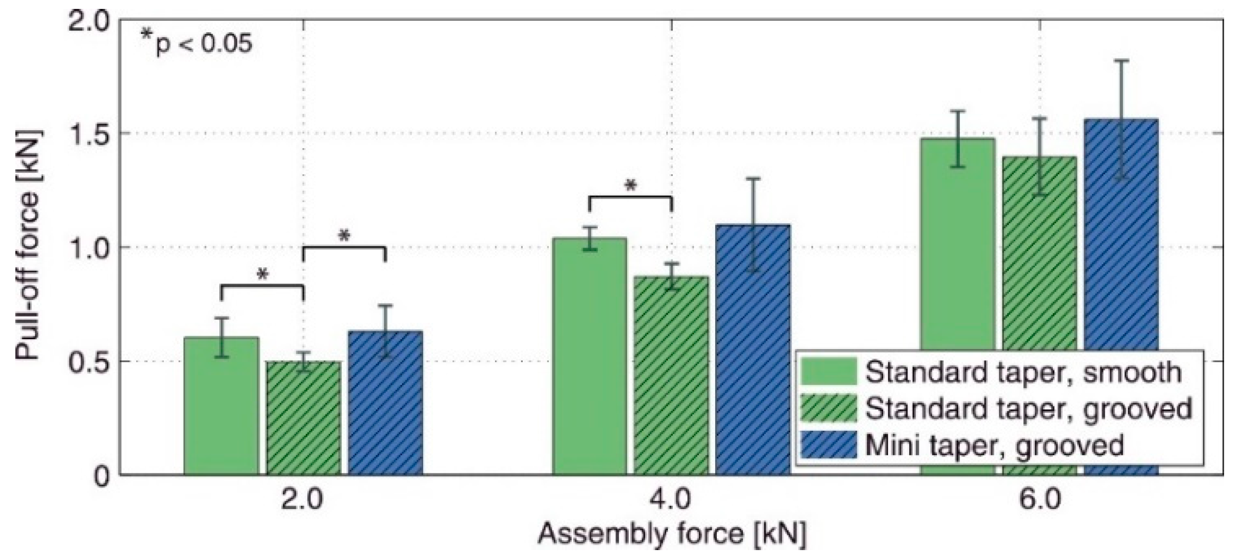
The coupling between assembly force and microgrooves was also reported by Matt et al. [24]. They evaluated the pull-off strength of a number of customized Ti trunnions with different lengths contacted with 28 mm CoCr heads. Three groups of junctions were selected for the experiments as standard/smooth, standard/grooved, and mini/grooved. When the assembly force was less than 4 kN, the smoothed junctions showed higher strengths. However, no significant change in strength with the surface finish was observed at 6 kN. For comparison, Figure 2 illustrates the difference between the pull-off strength of the junction groups considered in Matt et al. [24].
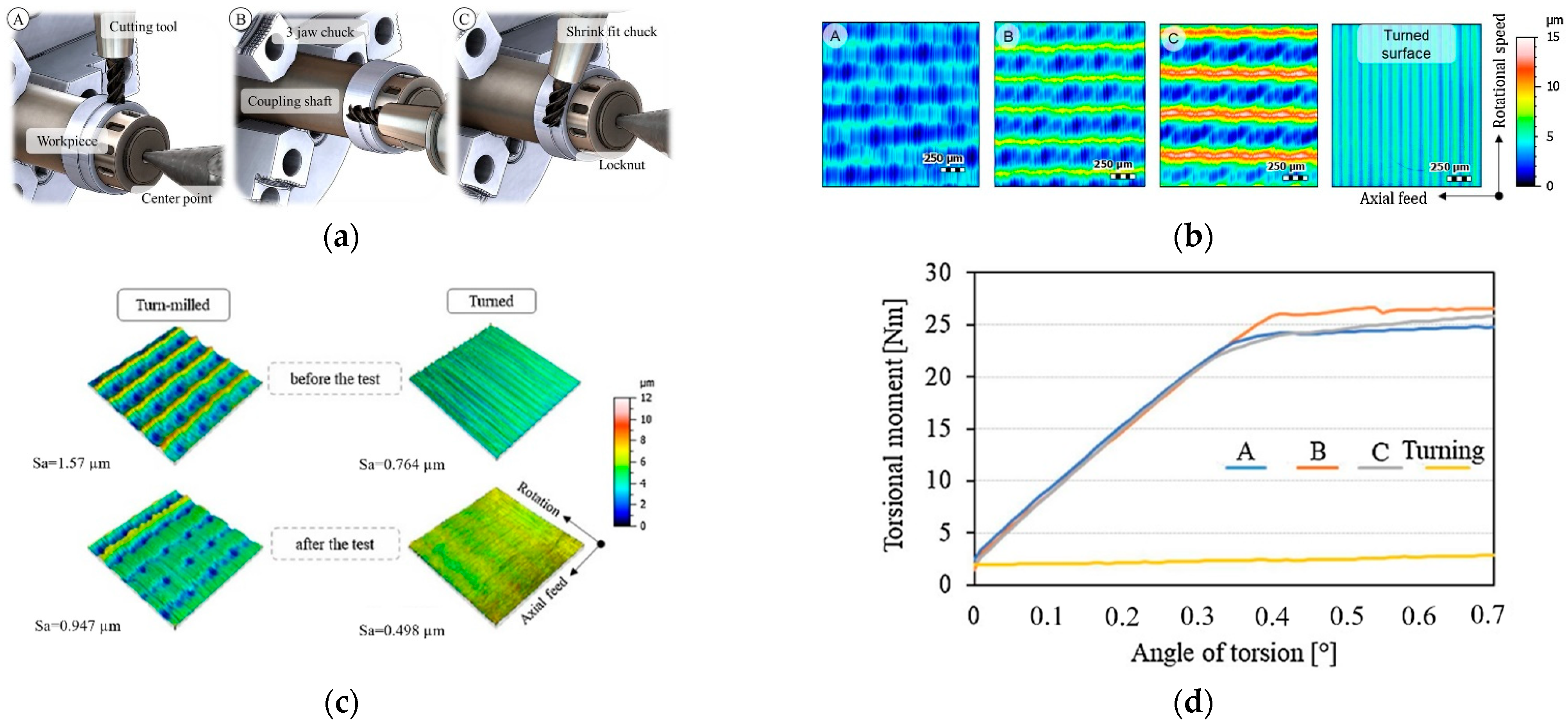
The strength of the turned taper junction was enhanced by the turn milling method in Döbberthin et al. [27]. It was shown that the topography on the trunnion surface changes with machining parameters significantly (Figure 3a–c). Figure 3d compares the dismantling torques of the junctions with different topographies.
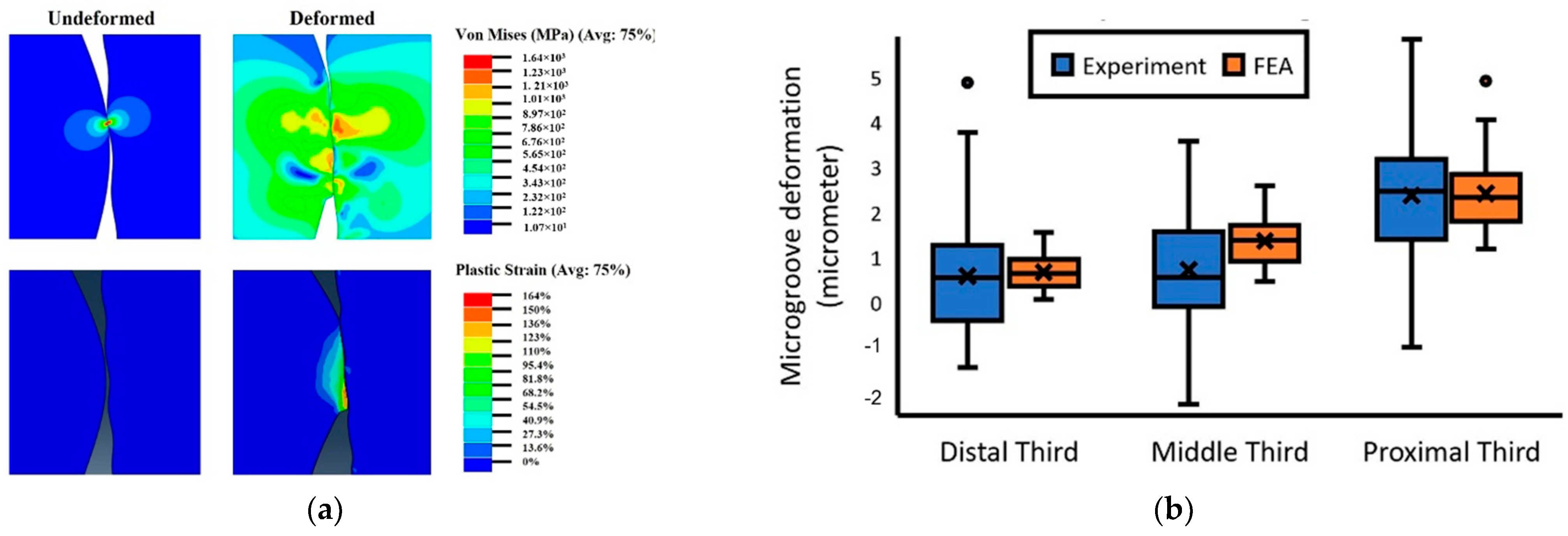
The published literature shows some studies in which the finite element (FE) approach was used to estimate the contact of the microgrooved junctions. Bechstedt et al. [31] observed significant changes in the contact of the microgrooved junctions after assemblage. Once verified, the results for three surface topographies with heights of 2, 1, and 14 µm showed the pivotal role played by the assembly force in altering the contact situation, whereas the deeper microgrooves resulted in a smaller contact area. For the junctions with a CoCr head, all microgrooves were in contact even with the lowest assembly force; however, for those with ceramic heads, few microgrooves were in contact. Godoy et al. [32] used a 2D axisymmetric model with a sinusoidal pattern of microgrooves on a trunnion. According to experimental and FE results, most of the microgrooves were deformed, which is partly inconsistent with the findings in [31]. Plastic deformation was noted in the FE models at the tip of the microgrooves, as illustrated in Figure 4a. Figure 4b shows the deformation in the microgroove at various regions. In addition to the taper angle mismatch, the deformation and contact pressure were indicated to be a function of the magnitude of assembly force in Gustafson et al. [33]. The change in assembly force from 4 kN to 12 kN changed the contact situation and plastic strains. The model in [33] was recently used in Gustafson et al. [34] to evaluate the influence of taper angle mismatch and microgroove pattern on the integrity. When comparing the contact area, the influence of trunnion microgroove pattern was the most important factor followed by the presence of microgrooves on the head taper.
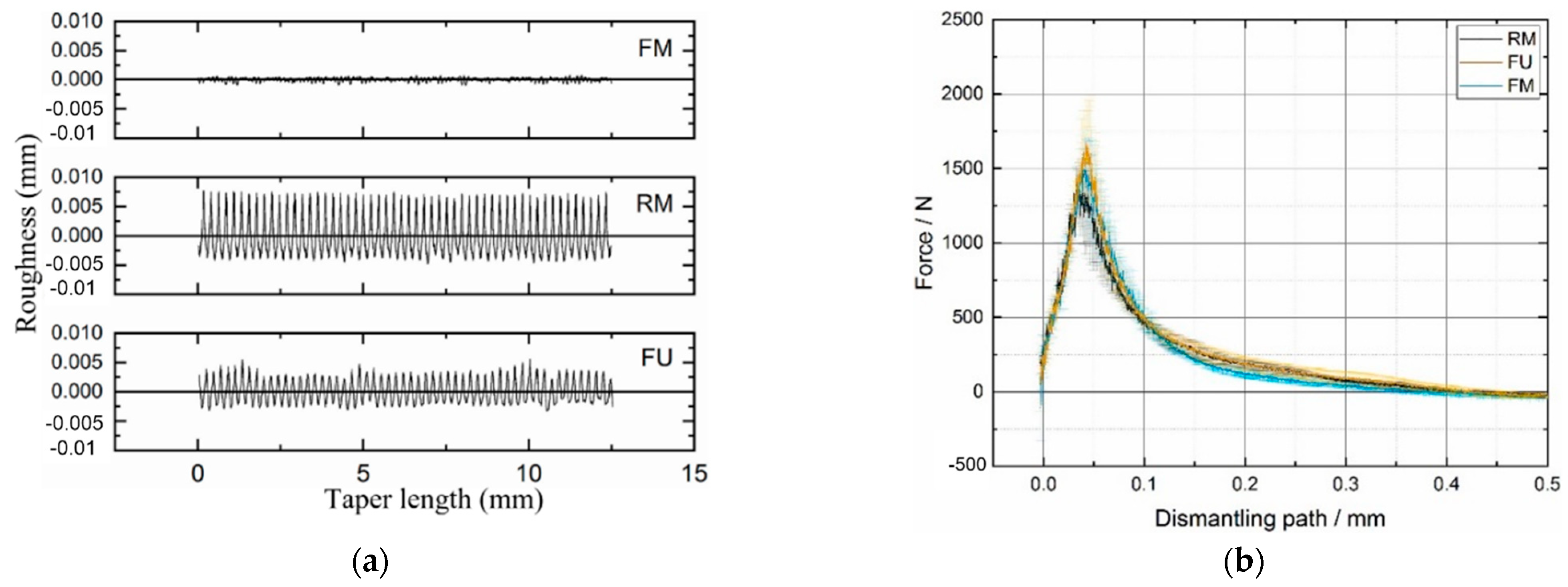
In contrast to the studies above, there are some studies which highlighted the negative or neutral influence of the microgrooves on the junction integrity. Mueller et al. [35] conducted an investigation on the influence of contact situation, trunnion topography, head material, and impaction force on the stability of the junctions. They reported the level of assembly force as the most important parameter in determining the twist-off strength followed by the head material. For higher assembly forces, higher twist-off strengths were observed. No significant influence of the surface topography on the twist-off moment was reported. This result was also partly confirmed by Mai et al. [28]. Three surface topographies (Figure 5a) were on the surface of the trunnions. Figure 5b shows the dismantling forces for the furrowing and rough machined taper junctions, respectively. In a study by Falkenberg et al. [36], it was demonstrated that the presence of microgrooves did not produce any changes in the micromotions.
The results reported in the aforementioned studies indicated that the microgrooved junctions have either a positive or a neutral effect on the junction integrity. Changing the influence is influenced by various design parameters. The experimentation of all the possible design shapes is not feasible in reality. As the FE approach has shown its capability in predicting the junction performance, it would be a wise movement if these models are continued with some stochastic FE analyses as used for smoothed junctions in Donaldson et al. [37].
2.2. Wear, Corrosion, and Material Loss
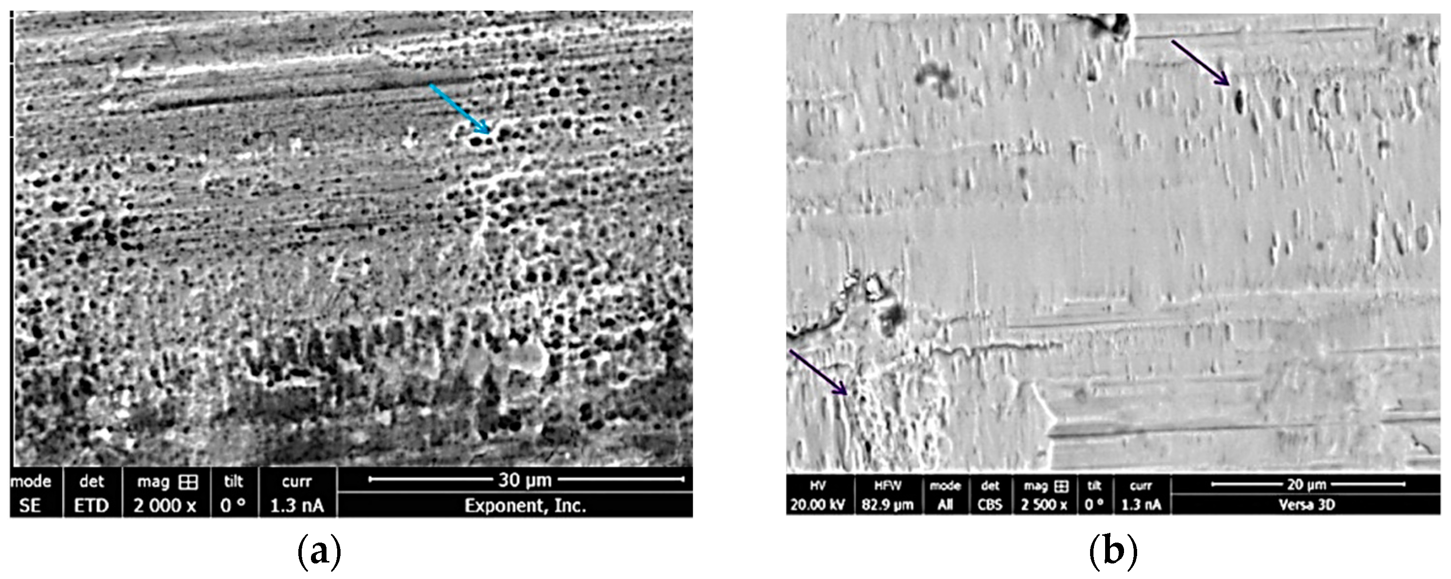
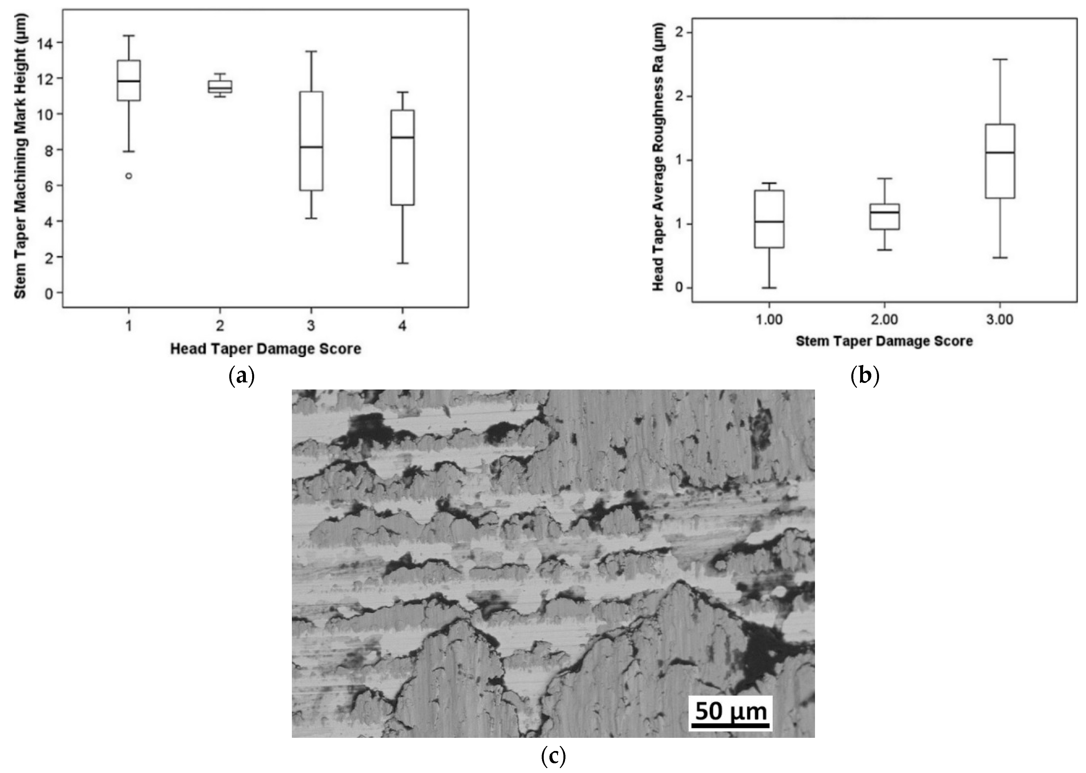
The stability and integrity of taper junctions are evaluated by indicative metrics to predict the life of the junctions against the wear/corrosion damage mechanism at the interface. Although useful and estimative, these metrics do not provide a valid prediction of the junction performance. In this section, the studies on the wear/corrosion of microgrooved junctions are focused, and their main results are presented. In this regard, a cohort study was conducted by Arnholt et al. [30] through which the junctions were classified into two groups. In one group, the mating trunnion was smooth while in the other, the microgrooved trunnions were used. The observation showed no difference in the maximal depth of material removal and fretting corrosion damage score of the two groups. Both groups showed signs of micromotions and fretting corrosion damage (Figure 6). Conversely, Panagiotidou et al. [38] reported the surface topography as one important parameter affecting the damage of the head–trunnion interfaces. The results showed the fracture of the oxide layer where a rough trunnion was used. This somewhat consists with the results found by Brock et al. [18], where rough trunnions represented higher volume loss rates. The fretting corrosion in head tapers was higher than that in the trunnions [18]. Considering the role of material couple, Pourzal et al. [39] more extensively investigated the wear/corrosion damage in head–trunnion junctions. It was observed that the damage scores of CoCr–CoCr junctions were higher compared to those of CoCr–Ti junctions. Higher fretting corrosion damage in CoCr has also been reported by Kop et al. [40]. The influence of the surface roughness for the two material combinations obtained in Pourzal et al.’s study [40] is illustrated in Figure 7. The contribution of roughness to higher material losses at the metal-on-metal junctions has been also reported by Hothi et al. [41]. Figure 8 shows a general comparison of the surface roughness of the two groups considered by Hothi et al. [41].
The variations of the surface topography were also raised in [26]. Stockhausen et al. [26] reported considerable variations in the surface topographies of different designs. They studied the influence of stem topography on the severity of fretting corrosion damage. It was observed that stems mated with ceramic heads were less damaged if they were mated with a smoother trunnion, while, in the case of having a metallic head, there was no influence of the surface roughness on the intensity. The scoring method was based on the approach proposed by Goldberg et al. [42].
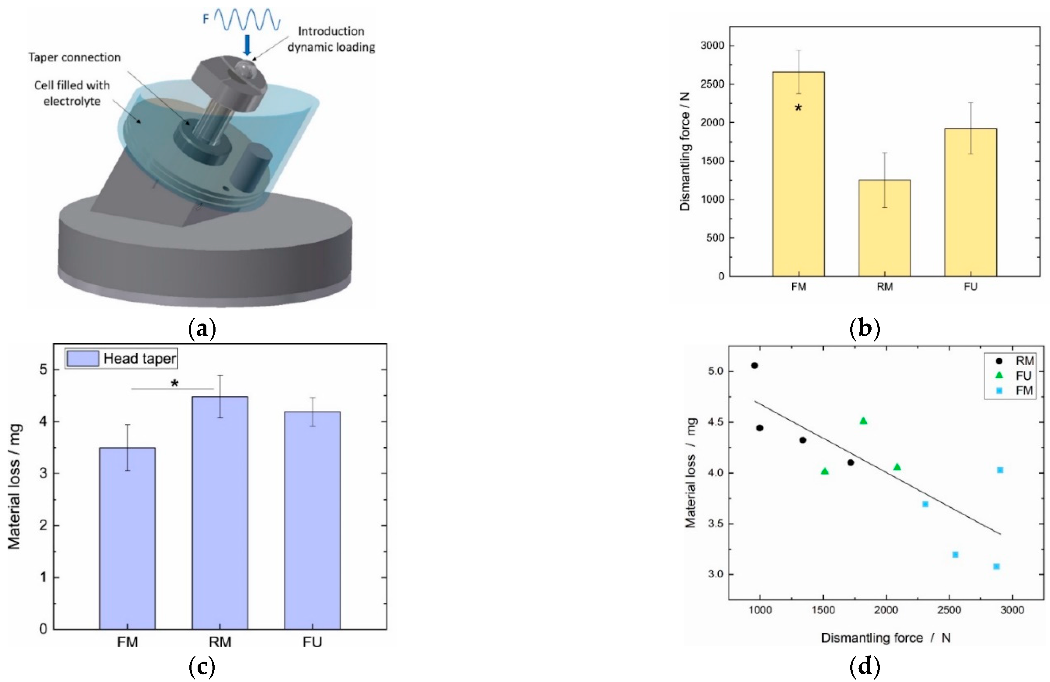
In the recent study by Mai et al. [28], a series of in-vitro fretting corrosion experiments were conducted. As shown schematically in Figure 9a, an off-axial sinusoidal load was applied to the junction immersed into an acidic solution. After completing the tests, the junctions were dismantled. It was observed that the stability was maximal for the fine machined junctions followed by furrowed ones and rough machined ones (Figure 9b). The material loss increased with an increase in the surface roughness (Figure 9c). Metal-on-metal junctions were suggested to be used with smoother trunnions as confirmed in Pourzal et al. [39]. Interestingly, a correlation was found between the dismantling force after the fretting corrosion tests and the material losses at the interface (Figure 9d).
Higher wear rates in the microgrooved junctions in comparison with the smoothed junctions were observed in one FE study by Ashkanfar et al. [43]. The ridges and their influence on the wear depth were also modeled by Zhang et al. [44] using a sub-modeling technique. It was shown that the wear depth in the sub-model was higher than that in the global model. A recent FE study by Capitanu et al. [45] also confirmed higher wear rate for microgrooved junctions consistent with those in [43][44]. In all FE simulations [43][44][45], the role of corrosion was neglected, and the total loss was assumed to originate from the mechanical wear only.
The comparison of all studies above seems to signify a message of higher volume losses for microgrooved junctions. In Section 2.1, it was observed that the stability and integrity of the junction are positively influenced by the microgrooves, while, in this section, the fretting corrosion of such junctions was more severe. There is a need to conduct more research studies on the microgrooved tapers as the previous research is limited in terms of the junction geometry while the variations among the designs are very large [26][27][28][46].
3. Summary
The mechanical performance of the microgrooved junctions versus smoothed junctions has been recently raised as a research question [27][30][31][36][43]. Previous findings and reported results are contradictory; furthermore, there is no agreement on the microgroove geometry. Some research studies support the main philosophy behind the creation of the microgrooves to enhance the junction integrity [24][25][27][31] while others report that microgrooved junctions reduce the integrity [28][36]. It seems that most of the literature studies concluded that microgrooves have a positive effect on the integrity. However, this positive influence seems to strongly depend on other design parameters such as the taper angle mismatch [34], assembly force [24][25], trunnion geometry [18], and head size/material [31][36]. The FE method has shown its capability in predicting the behavior of the microgrooved junctions [4][5][31][33][34][36]. This modeling procedure might be concluded with an optimal pattern for the microgroove geometry. The FE models of microgrooved junctions are still in their infancy, and they do not accurately reflect what occurs in reality. In operation, the junction is typically assembled off-axially with head tapers for which the roughness is not negligible. Then, the junction undergoes cyclic loads [4][5][19][20] in the corrosive body medium. Some of these activities might result in critical stress and strain fields [4][5]. The FE work completed by Ashkanfar et al. [43] addresses the mechanical wear; however, it does not include the head taper roughness and corrosion effects similar to the recent research by Capitanu et al. [45]. The chapter of the microgrooved junctions is still open, and more research needs to be conducted. The inclusion of the electrochemical reactions at the interface was recently applied to a smoothed junction by the scholars [11]. The role of mechanical and electrochemical reactions in the total tribocorrosion loss changes with various parameters such as the imposed potential [47][48], normal force [49][50], sliding distance and its frequency [51][52][53], material couple in contact [54][55][56][57], and the solution acidity [58][59][60]. These complexities need to be comprehensively included in the experimental tests before the incorporation of the experimental data into the numerical models. In the presence of the microgrooves, the role of the mechanical and electrochemical reactions might be increased and/or decreased. By the inclusion of these complexities, the modeling procedure might generate a more conclusive comparison between microgrooved and smoothed junctions. Although being indicative and useful, most of the retrieval studies conducted on the microgrooved junctions focused on a class of junctions with various geometrical parameters and they sometimes did not give details on the geometry of the microgrooves and/or the loading history of the junction. Keeping the strong interactions of the design parameters in mind, the microgrooved junctions need to be studied more meticulously with possible inclusion of the complexities in both the operational and the post-operational phases.
This entry is adapted from the peer-reviewed paper 10.3390/ma15238396
References
- Hussenbocus, S.; Kosuge, D.; Solomon, L.B.; Howie, D.W.; Oskouei, R.H. Head-Neck Taper Corrosion in Hip Arthroplasty. BioMed Res. Int. 2015, 2015, 1–9. [Google Scholar] [CrossRef] [PubMed]
- Oskouei, R.H.; Barati, M.R.; Farhoudi, H.; Taylor, M.; Solomon, L.B. A new finding on the in-vivo crevice corrosion damage in a CoCrMo hip implant. Mater. Sci. Eng. C 2017, 79, 390–398. [Google Scholar] [CrossRef] [PubMed]
- Hernigou, P.; Queinnec, S.; Lachaniette, C.-H.F. One hundred and fifty years of history of the Morse taper: From Stephen A. Morse in 1864 to complications related to modularity in hip arthroplasty. Int. Orthop. 2013, 37, 2081–2088. [Google Scholar] [CrossRef] [PubMed]
- Feyzi, M.; Fallahnezhad, K.; Taylor, M.; Hashemi, R. A review on the finite element simulation of fretting wear and corrosion in the taper junction of hip replacement implants. Comput. Biol. Med. 2020, 130, 104196. [Google Scholar] [CrossRef] [PubMed]
- Feyzi, M.; Fallahnezhad, K.; Taylor, M.; Hashemi, R. The mechanics of head-neck taper junctions: What do we know from finite element analysis? J. Mech. Behav. Biomed. Mater. 2021, 116, 104338. [Google Scholar] [CrossRef]
- Haschke, H.; Konow, T.; Huber, G.; Morlock, M.M. Influence of flexural rigidity on micromotion at the head-stem taper interface of modular hip prostheses. Med. Eng. Phys. 2019, 68, 1–10. [Google Scholar] [CrossRef]
- Fallahnezhad, K.; Farhoudi, H.; Oskouei, R.H.; Taylor, M. Influence of geometry and materials on the axial and torsional strength of the head–neck taper junction in modular hip replacements: A finite element study. J. Mech. Behav. Biomed. Mater. 2016, 60, 118–126. [Google Scholar] [CrossRef]
- Lee, Y.-K.; Lee, J.-C.; Ha, Y.-C.; Koo, K.-H. Effect of neck length on third-generation ceramic head failure; finite element and retrieval analysis. J. Orthop. Sci. 2014, 19, 587–597. [Google Scholar] [CrossRef]
- Mistry, J.B.; Chughtai, M.; Elmallah, R.K.; Diedrich, A.; Le, S.; Thomas, M.; Mont, M.A. Trunnionosis in total hip arthroplasty: A review. J. Orthop. Traumatol. 2016, 17, 1–6. [Google Scholar] [CrossRef]
- Wight, C.M.; Lanting, B.; Schemitsch, E.H. Evidence Based Recommendations for Reducing Head-Neck Taper Connection Fretting Corrosion in Hip Replacement Prostheses. HIP Int. 2017, 27, 523–531. [Google Scholar] [CrossRef]
- Fallahnezhad, K.; Feyzi, M.; Ghadirinejad, K.; Hashemi, R.; Taylor, M. Finite element based simulation of tribocorrosion at the head-neck junction of hip implants. Tribol. Int. 2021, 165, 107284. [Google Scholar] [CrossRef]
- Fallahnezhad, K.; Oskouei, R.H.; Badnava, H.; Taylor, M. An adaptive finite element simulation of fretting wear damage at the head-neck taper junction of total hip replacement: The role of taper angle mismatch. J. Mech. Behav. Biomed. Mater. 2017, 75, 58–67. [Google Scholar] [CrossRef]
- Shareef, N.; Levine, D. Effect of manufacturing tolerances on the micromotion at the Morse taper interface in modular hip implants using the finite element technique. Biomaterials 1996, 17, 623–630. [Google Scholar] [CrossRef]
- Raji, H.Y.; Shelton, J.C. Prediction of taper performance using quasi static FE models: The influence of loading, taper clearance and trunnion length. J. Biomed. Mater. Res. Part B Appl. Biomater. 2018, 107, 138–148. [Google Scholar] [CrossRef] [PubMed]
- Lavernia, C.J.; Iacobelli, D.S.; Villa, J.M.; Jones, K.; Gonzalez, J.L.; Jones, W.K. Trunnion–Head Stresses in THA: Are Big Heads Trouble? J. Arthroplast. 2015, 30, 1085–1088. [Google Scholar] [CrossRef] [PubMed]
- Vogel, D.; Falkenberg, A.; Bierbaum, S.; Schulze, C.; Bader, R.; Kluess, D. Mechanical Stability of the Taper Connection of Large Metal Femoral Heads With Adapter Sleeves in Total Hip Arthroplasty Analyzed Using Explicit Finite Element Simulations. J. Arthroplast. 2017, 32, 2580–2586. [Google Scholar] [CrossRef]
- Fernandez-Fairen, M. CORRInsights®: Does Surface Topography Play a Role in Taper Damage in Head-neck Modular Junctions? Clin. Orthop. Relat. Res. 2016, 474, 2243–2245. [Google Scholar] [CrossRef]
- Brock, T.M.; Sidaginamale, R.; Rushton, S.; Nargol, A.V.; Bowsher, J.G.; Savisaar, C.; Joyce, T.J.; Deehan, D.J.; Lord, J.K.; Langton, D.J. Shorter, rough trunnion surfaces are associated with higher taper wear rates than longer, smooth trunnion surfaces in a contemporary large head metal-on-metal total hip arthroplasty system. J. Orthop. Res. 2015, 33, 1868–1874. [Google Scholar] [CrossRef]
- Fallahnezhad, K.; Farhoudi, H.; Oskouei, R.H.; Taylor, M. A finite element study on the mechanical response of the head-neck interface of hip implants under realistic forces and moments of daily activities: Part 2. J. Mech. Behav. Biomed. Mater. 2018, 77, 164–170. [Google Scholar] [CrossRef]
- Farhoudi, H.; Fallahnezhad, K.; Oskouei, R.H.; Taylor, M. A finite element study on the mechanical response of the head-neck interface of hip implants under realistic forces and moments of daily activities: Part 1, level walking. J. Mech. Behav. Biomed. Mater. 2017, 75, 470–476. [Google Scholar] [CrossRef]
- Fallahnezhad, K.; Oskouei, R.H.; Badnava, H.; Taylor, M. The Influence of Assembly Force on the Material Loss at the Metallic Head-Neck Junction of Hip Implants Subjected to Cyclic Fretting Wear. Metals 2019, 9, 422. [Google Scholar] [CrossRef]
- Danoff, J.R.; Longaray, J.; Rajaravivarma, R.; Gopalakrishnan, A.; Chen, A.F.; Hozack, W.J. Impaction Force Influences Taper-Trunnion Stability in Total Hip Arthroplasty. J. Arthroplast. 2018, 33, S270–S274. [Google Scholar] [CrossRef] [PubMed]
- Grosso, M.J.; Jang, E.S.; Longaray, J.; Buell, S.; Alfonso, E.; Shah, R.P. Influence of Assembly Force and Distraction on the Femoral Head-Taper Junction. J. Arthroplast. 2018, 33, S275–S279. [Google Scholar] [CrossRef]
- Jauch-Matt, S.; Miles, A.; Gill, H. Effect of trunnion roughness and length on the modular taper junction strength under typical intraoperative assembly forces. Med Eng. Phys. 2016, 39, 94–101. [Google Scholar] [CrossRef]
- Dransfield, K.; Racasan, R.; Williamson, J.; Bills, P. Changes in the morphology of microgrooved stem tapers with differing assembly conditions. Biotribology 2019, 18, 100096. [Google Scholar] [CrossRef]
- Stockhausen, K.E.; Riedel, C.; Belinski, A.V.; Rothe, D.; Gehrke, T.; Klebig, F.; Gebauer, M.; Amling, M.; Citak, M.; Busse, B. Variability in stem taper surface topography affects the degree of corrosion and fretting in total hip arthroplasty. Sci. Rep. 2021, 11, 9348. [Google Scholar] [CrossRef] [PubMed]
- Döbberthin, C.; Herbster, M.; Karpuschewski, B. A novel approach for a modular taper junction in hip stems using turn-milling. CIRP J. Manuf. Sci. Technol. 2021, 33, 256–263. [Google Scholar] [CrossRef]
- Mai, P.T.; Bormann, T.; Müller, U.; Kretzer, J.P.; Gibmeier, J. Effect of surface topography and residual stress on the taper connection stability in total hip arthroplasty. J. Mech. Behav. Biomed. Mater. 2022, 128, 105119. [Google Scholar] [CrossRef]
- Arnholt, C.; Underwood, R.; MacDonald, D.W.; Higgs, G.B.; Chen, A.F.; Klein, G.; Hamlin, B.; Lee, G.-C.; Mont, M.; Cates, H.; et al. Microgrooved Surface Topography does not Influence Fretting Corrosion of Tapers in Total Hip Arthroplasty: Classification and Retrieval Analysis. In Modularity and Tapers in Total Joint Replacement Devices; ASTM International: West Conshohocken, PA, USA, 2015. [Google Scholar]
- Arnholt, C.M.; MacDonald, D.W.; Underwood, R.J.; Guyer, E.P.; Rimnac, C.M.; Kurtz, S.M.; Mont, M.A.; Klein, G.R.; Lee, G.-C.; Chen, A.F.; et al. Do Stem Taper Microgrooves Influence Taper Corrosion in Total Hip Arthroplasty? A Matched Cohort Retrieval Study. J. Arthroplast. 2016, 32, 1363–1373. [Google Scholar] [CrossRef] [PubMed]
- Bechstedt, M.; Gustafson, J.A.; Mell, S.P.; Gührs, J.; Morlock, M.M.; Levine, B.R.; Lundberg, H.J. Contact conditions for total hip head-neck modular taper junctions with microgrooved stem tapers. J. Biomech. 2020, 103, 109689. [Google Scholar] [CrossRef]
- Godoy, M.; Gustafson, J.A.; Hertzler, J.S.; Bischoff, J.E.; Pourzal, R.; Lundberg, H.J. Model validation for estimating taper microgroove deformation during total hip arthroplasty head-neck assembly. J. Biomech. 2022, 140, 111172. [Google Scholar] [CrossRef] [PubMed]
- Gustafson, J.A.; Pourzal, R.; Levine, B.R.; Jacobs, J.J.; Lundberg, H.J. Modelling changes in modular taper micromechanics due to surgeon assembly technique in total hip arthroplasty. Bone Jt. J. 2020, 102-B, 33–40. [Google Scholar] [CrossRef] [PubMed]
- Gustafson, J.A.; Mell, S.P.; Levine, B.R.; Pourzal, R.; Lundberg, H.J. Interaction of surface topography and taper mismatch on head-stem modular junction contact mechanics during assembly in modern total hip replacement. J. Orthop. Res. 2022. [Google Scholar] [CrossRef] [PubMed]
- Mueller, U.; Bormann, T.; Schroeder, S.; Kretzer, J.P. Taper junctions in modular hip joint replacements: What affects their stability? J. Mech. Behav. Biomed. Mater. 2021, 116, 104258.
- Falkenberg, A.; Biller, S.; Morlock, M.M.; Huber, G. Micromotion at the head-stem taper junction of total hip prostheses is influenced by prosthesis design-, patient- and surgeon-related factors. J. Biomech. 2019, 98, 109424.
- Donaldson, F.E.; Coburn, J.C.; Siegel, K.L. Total hip arthroplasty head–neck contact mechanics: A stochastic investigation of key parameters. J. Biomech. 2014, 47, 1634–1641.
- Panagiotidou, A.; Meswania, J.; Hua, J.; Muirhead-Allwood, S.; Hart, A.; Blunn, G. Enhanced wear and corrosion in modular tapers in total hip replacement is associated with the contact area and surface topography. J. Orthop. Res. 2013, 31, 2032–2039.
- Pourzal, R.; Hall, D.J.; Ha, N.Q.; Urban, R.M.; Levine, B.R.; Jacobs, J.J.; Lundberg, H.J. Does Surface Topography Play a Role in Taper Damage in Head-neck Modular Junctions? Clin. Orthop. Relat. Res. 2016, 474, 2232–2242.
- Kop, A.M.; Keogh, C.; Swarts, E. Proximal Component Modularity in THA—At What Cost?: An Implant Retrieval Study. Clin. Orthop. Relat. Res. 2012, 470, 1885–1894.
- Hothi, H.S.; Whittaker, R.K.; Meswania, J.M.; Blunn, G.W.; A Skinner, J.; Hart, A.J. Influence of stem type on material loss at the metal-on-metal pinnacle taper junction. Proc. Inst. Mech. Eng. Part H J. Eng. Med. 2015, 229, 91–97.
- Goldberg, J.R.; Gilbert, J.L.; Jacobs, J.; Bauer, T.; Paprosky, W.; Leurgans, S. A Multicenter Retrieval Study of the Taper Interfaces of Modular Hip Prostheses. Clin. Orthop. Relat. Res.
- Ashkanfar, A.; Langton, D.J.; Joyce, T.J. Does a micro-grooved trunnion stem surface finish improve fixation and reduce fretting wear at the taper junction of total hip replacements? A finite element evaluation. J. Biomech. 2017, 63, 47–54.
- Zhang, T.; Harrison, N.M.; McDonnell, P.F.; E McHugh, P.; Leen, S.B. Micro–macro wear–fatigue of modular hip implant taper-lock coupling. J. Strain Anal. Eng. Des. 2013, 49, 2–18.
- Capitanu, L.; Badita, L.-L.; Tiganesteanu, C.; Florescu, V. Influence of the taper on the fretting wear of the femoral stem-femoral head taper junction in total hip prosthesis. Ind. Lubr. Tribol. 2021, 74, 385–391.
- Mueller, U.; Braun, S.; Schroeder, S.; Sonntag, R.; Kretzer, J.P. Same Same but Different? 12/14 Stem and Head Tapers in Total Hip Arthroplasty. J. Arthroplast. 2017, 32, 3191–3199.
- Runa, M.; Mathew, M.; Rocha, L. Tribocorrosion response of the Ti6Al4V alloys commonly used in femoral stems. Tribol. Int. 2013, 68, 85–93.
- Feyzi, M.; Fallahnezhad, K.; Taylor, M.; Hashemi, R. The Tribocorrosion Behaviour of Ti-6Al-4 V Alloy: The Role of Both Normal Force and Electrochemical Potential. Tribol. Lett. 2022, 70, 83.
- Sadiq, K.; Black, R.; Stack, M. Bio-tribocorrosion mechanisms in orthopaedic devices: Mapping the micro-abrasion–corrosion behaviour of a simulated CoCrMo hip replacement in calf serum solution. Wear 2014, 316, 58–69.
- Maldonado, S.G.; Mischler, S.; Cantoni, M.; Chitty, W.-J.; Falcand, C.; Hertz, D. Mechanical and chemical mechanisms in the tribocorrosion of a Stellite type alloy. Wear 2013, 308, 213–221.
- Namus, R.; Nutter, J.; Qi, J.; Rainforth, W. Sliding speed influence on the tribo-corrosion behaviour of Ti6Al4V alloy in simulated body fluid. Tribol. Int. 2021, 160, 107023.
- Swaminathan, V.; Gilbert, J.L. Potential and frequency effects on fretting corrosion of Ti6Al4V and CoCrMo surfaces. J. Biomed. Mater. Res. Part A 2013, 101A, 2602–2612.
- Feyzi, M.; Fallahnezhad, K.; Taylor, M.; Hashemi, R. What role do normal force and frequency play in the tribocorrosion behaviour of Ti-6Al-4 V alloy? Tribol. Int. 2022, 172, 107634.
- Çaha, I.; Alves, A.; Chirico, C.; Tsipas, S.; Rodrigues, I.; Pinto, A.; Grandini, C.; Rocha, L.; Gordo, E.; Toptan, F. Interactions between wear and corrosion on cast and sintered Ti-12Nb alloy in comparison with the commercial Ti-6Al-4V alloy. Corros. Sci. 2020, 176, 108925.
- Doni, Z.; Alves, A.; Toptan, F.; Gomes, J.; Ramalho, A.; Buciumeanu, M.; Palaghian, L.; Silva, F. Dry sliding and tribocorrosion behaviour of hot pressed CoCrMo biomedical alloy as compared with the cast CoCrMo and Ti6Al4V alloys. Mater. Des. 2013, 52, 47–57.
- Swaminathan, V.; Gilbert, J.L. Fretting corrosion of CoCrMo and Ti6Al4V interfaces. Biomaterials 2012, 33, 5487–5503.
- Fallahnezhad, K.; Feyzi, M.; Taylor, M.; Hashemi, R. What is the relationship between metal-on-metal and ceramic-on-metal tribocorrosive behaviours? An experimental study on Ti-6Al-4 V/CoCrMo interface. Tribol. Int. 2022, 174, 107720.
- Espallargas, N.; Torres, C.; Muñoz, A. A metal ion release study of CoCrMo exposed to corrosion and tribocorrosion conditions in simulated body fluids. Wear 2015, 332–333, 669–678.
- Yan, Y.; Neville, A.; Dowson, D. Biotribocorrosion of CoCrMo orthopaedic implant materials—Assessing the formation and effect of the biofilm. Tribol. Int. 2007, 40, 1492–1499.
- Liu, Y.; Gilbert, J.L. The effect of simulated inflammatory conditions and pH on fretting corrosion of CoCrMo alloy surfaces. Wear 2017, 390–391, 302–311.