Your browser does not fully support modern features. Please upgrade for a smoother experience.

Please note this is an old version of this entry, which may differ significantly from the current revision.
Increases in power density and thermal efficiency of a highly efficient gas turbine engine motivate an ever-mounting turbine entry temperature. The combined metallurgical and cooling advancements ensure the structural integrity of a gas turbine rotor blade that spins at high rotor speeds in a gas stream with temperatures above the melting point of the blade material. The advancements in the cooling technology for a gas turbine rotor blade are summarized.
- gas turbine rotor blade
- rib
- dimple
- impingement
1. Leading-Edge Cooling
1.1. Rotating Channels with Impinging Jets
With diminished boundary layers at the stagnation (impingement) point on a target plate of a jet flow, the localized high heat trashier rate of an impinging jet is utilized to counteract the peak external heat flux along the leading edge of a gas turbine rotor blade. Hsieh et al. [1] examined the effect of impinging jet location on the heat transfer performance of the rotating ribbed channels. Rotation suppressed the heat transfer performance from those without rotation. While there was 20–30% heat transfer enhancement by the transverse ribs, the heat transfer enhancement (HTE) impact induced by the square rib was higher than that with a semi-circular rib. Adreini et al. [2] adopted the steady-state liquid crystal method to measure the Nu map on the internal concave surface of a rotating channel with impinging jets to reveal the effects of different mass flow extraction from the pressure and suction side at two crossflow configurations corresponding to 70% (blade hub section) and 10% (blade tip section) of the total cooling flow. The effects of the extraction hole area and position on heat transfer performance, both in terms of averaged Nu levels and local Nu distribution, were secondary with respect to the jet Reynolds number and crossflow ratio. This research group also investigated the cold-bridge-type leading-edge rotating channel with impinging jets emitted from a cavity and spent air extracted through five rows of effusion holes [3]. The heat transfer characteristics were dominated by the jet Reynolds number, whereas the jet ejection and extraction conditions affected the distribution patterns of Nu maps. Rotation tended to undermine the cooling performance, and such an effect was an augmented increase as crossflow diminished. Furlani et al. [4] conduced the flow measurements of an advanced leading-edge cooling channel with multiple impinging jets and coolant extraction by means of 2D and Stereo PIV in static and rotating conditions at an Ro of 0.05. The Ro (Coriolis force) effect on the jet structure was not significant but caused a strong crossflow deflection toward the trailing wall (pressure side) that enhanced in magnitude from hub-to-tip sections. Near the channel tip, the unbalanced flow field toward the suction side of the feeding channel was strong enough to sustain a recirculating region downstream of the central jet hole. Elston and Wright [5] studied the effect of rotation on the cooling performance of an impinging jet row in a smooth square channel, with the jets impinging on a semi-circular concave surface and the spent flow expelled through effusion holes. With pure jet impingement, the deflected impinging jet co-acts with the secondary flows induced by rotation to augment fluid mixings in the impingement cavity that promote its cooling performance. With a strong crossflow, the Nusselt numbers in static and rotating channels were similar. Singh and Ekkad [6] studied the effects of Coriolis force and centrifugal buoyancy on heat transfer of a rotating dimpled channel with impinging jets using transient liquid crystal thermography. The rotational effect was beneficial for enhancing heat transfer on leading and trailing walls for the smooth-walled channel but exerted negative effects on heat transfer enhancement over the dimpled target surface. The higher Nusselt numbers emerged on the leading wall in the impingement dominant regime, but this effect was diminished with the increased strength of the crossflow. Chang and Yu [7] used infrared thermography to detect the endwall Nu maps and Fanning friction factors of the rotating trapezoidal channel with an impinging jet row at a channel orientation of 45° from the rotating axis. Acting by the Coriolis forces on the radially outward crossflow and the impinging jets, the airflow rates issued from the jets adjacent to the channel hub (tip) were increased (decreased) compared with those in the static impinging channel. The deteriorated heat transfer performance over the cavity-like channel hub region was considerably improved by the rotational force. The rotating buoyancy effect impaired cooling performance, but its effect was weakened as Ro increased. Wang et al. [8] measured the local Nusselt numbers in a rotating rectangular channel with impingement jet and effusion holes at a jet rotation number (buoyancy number) which varied from 0–0.24 (0–0.57) for three channel orientation angles of 90, 135, and 180 degrees. At a channel orientation angle of 135°, the Coriolis force deflected the jet and undermined the regional cooling performance. The distribution patterns of Nu were not obviously modified by Bu but were sensitive to the channel orientation angle owing to the altered Coriolis flow structures and the different bending direction for the impingement jet. Deng et al. [9] studied the rotational effects on the cooling performance of a rotating channel with impinging jets and air extraction with the aid of flow simulation results. The cooling effect on the suction side was superior to its pressure-side counterpart. The non-uniform jet flow variation deteriorated the cooling performance from channel tip-to-hub sections. Rotation boosts the non-uniformity of mass flux, resulting in a local heat transfer increase by 140% over the hub region on the pressure surface. This research group then focused on the effect of channel orientation on the jet flows and their heat transfer performances [10]. With the channel orientation angle between 90° and 135°, the Coriolis force induced a large vortex in the feeding channel to alter the mass flux distribution of the jet flow. Cooling performances in the middle and both channel ends were, respectively, undermined and promoted. When the channel orientation yielded to 135°–180°, the stagnation heat transfer zone decreased with Ro. The jet diversion induced by rotation became the primary factor for heat transfer impediments, yet the jets were also driven away from the impinging wall at high Ro.
1.2. Rotating Channels with Swirl Chamber
Gleze et al. [11] pioneered the effect of rotation on heat transfer in a screw-shaped swirl chamber for leading-edge cooling in a gas turbine rotor blade. The Coriolis force promoted (undermined) cooling effectiveness when its direction coincided (opposed) with the tangential velocity of the swirling flow. The centrifugal buoyancy effect was negligible for the overall cooling effect but led to redistribution of the Nusselt number. Rao et al. [12] reported a comparative study for the heat transfer and pressure loss characteristics in the rotating swirl tubes with one (S1) and five (S5) tangential inlet jets under equal overall mass flow rates and inlet jet Reynolds numbers, respectively. With similar overall mass flow rates, the heat transfer and pressure loss coefficients for the S1 swirl tube were significantly higher than the swirl tube S5. However, the swirl tube S5 exhibited a more uniform heat transfer distribution along the swirl tube. With similar jet Reynolds numbers, the tube average Nu of swirl tube S5 exceeded its S1 counterpart. The crossflow effect was not detrimental to the heat transfer performances in the S5 swirl tube. Wang et al. [13] carried out a numerical study to explore the effects of jet hole shape and channel geometry on leading-edge impinging cooling channels in static and rotating conditions. The impinging jet issued from the racetrack-shaped hole effectively persisted under an intensive crossflow to promote cooling performances. Their double-swirling chamber channel lessened the adverse Coriolis force effect with considerable HTE impacts and uniform temperature distributions. As Ro increased, the Nusselt numbers on the LE and TE decreased with Ro, in particular with high Re. Tansakul [14] numerically studied the buoyancy effect on the cooling performance of a rotating double-swirling chamber in engine realistic conditions using SST k-ω turbulence models. With the twin swirls induced by the spent fluid flows of the central impinging jet, the Nu peak constantly developed at the stagnation point along the periphery of the rotating target wall. The buoyancy effect yielded the peripheral Nu profile to be asymmetric at the impingement point and undermined the channel average Nu and thermal performance factor by 40.43% and 39.80%, respectively. The impaired cooling performance by the buoyancy effect in rotating conditions suggested the significance of buoyancy force for designing the particular double-swirling chamber in the leading edge of a gas turbine rotor blade.
2. Mid-Chord Region Cooling
In the mid-chord region of a gas turbine rotor blade, the orientation and shape of an internal coolant channel are varied in the chord-wise direction to fit the interior geometry of the airfoil. Rectangular channels with different channel width-to-height ratios (aspect ratios, AR), parallelogram channels, and trapezoidal channels are widely deployed in the cooling network over the mid-chord region. As the periphery of a rotating channel confines the sectional vortical flows induced by the Coriolis forces, the aerothermal performance of a non-circular rotating channel is affected by its shape and orientation. The effects of channel shape, orientation, and HTE elements on the aerothermal performance of a single- or multi-pass rotating channel are extensively studied. In particular, the serpentine coolant passage is in common use for saving the coolant consumption over the mid-chord region. Apart from the saving initiative of coolant consumption, a multi-pass channel was attempted for taking the HTE advantages attributed to Coriolis forces by configuring its coolant walls in contact with the hot gas as the unstable sides of the flow passages with radial outflow and inflow [15]. It is noted that this cooling concept is mostly applicable for mid-chord region cooling. The data generated by the research group [15] is reprocessed from Nu/Ren to Nu/Nu0 for highlighting the effects of rotation on the two unstable sides of the flow passages. In Figure 1a, the two-pass channel is separated by the central divider to construct the entry (exit) pass with radial outflow (inflow). The unstable channel walls toward which the core cold coolant is directed by Coriolis forces in these two rotating passes are adjacent to the hot gas to take advantage of the HTE benefits from the Coriolis forces. In Figure 1b, all the heat transfer levels on the channel hot walls at the channel orientation angles of 0° and 45° keep increasing with Ro from Ro = 0 to Ro = 1 along the rotating two-pass trapezoidal ribbed channel.
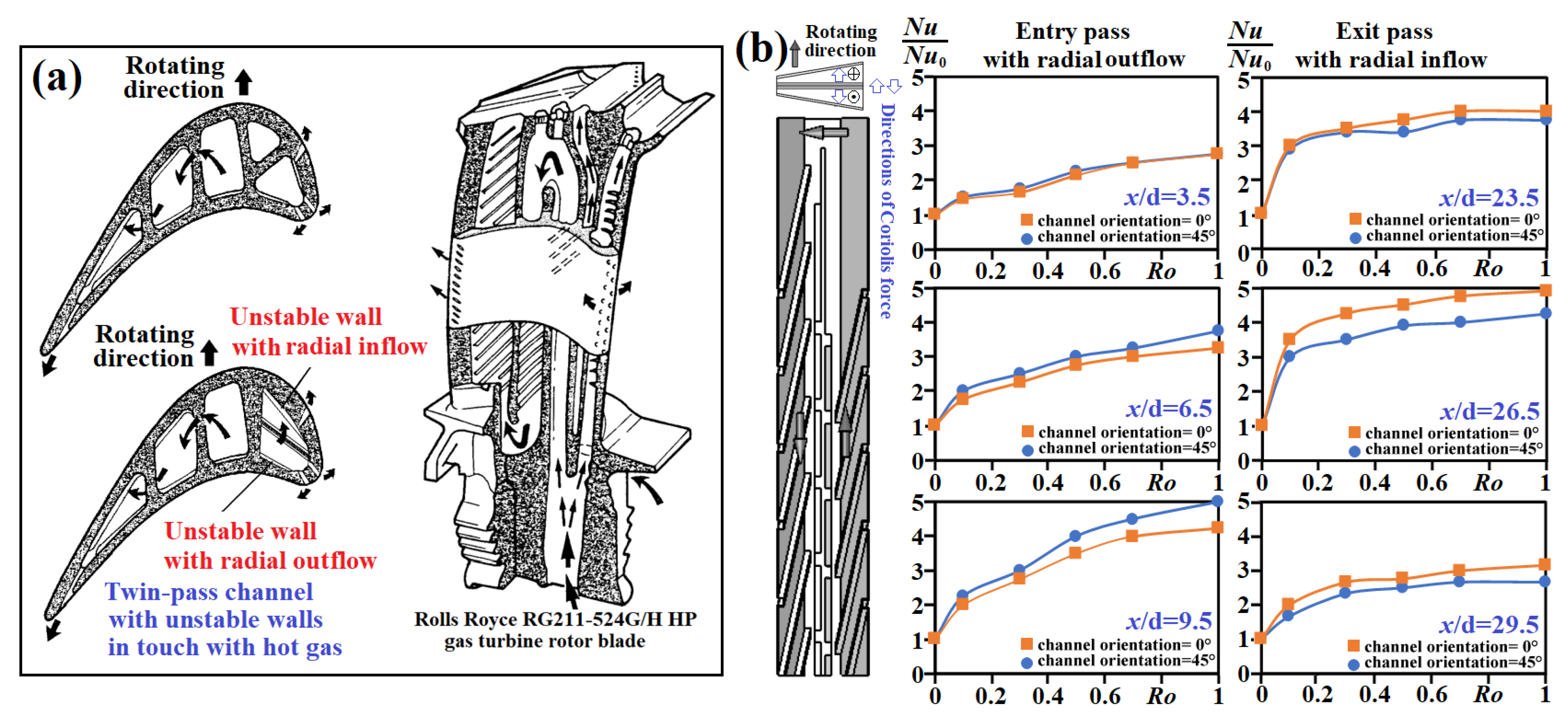
Figure 1. (a) Internal cooling concept for utilizing a positive HTE Coriolis force effect by installing a twin-pass trapezoidal channel in a gas turbine rotor blade (b) variations of normalized Nusselt number against Ro at different axial locations demonstrating the improved cooling effectiveness with Ro.
Recently, Guo et al. [16] suggested positive utilization of the Coriolis force effect to boost the cooling effectiveness on the heated channel wall as the Coriolis-utilization rotating condition to investigate the flow structures and heat transfer characteristics of a rotating smooth two-pass U-channel in stationary, conventional rotating, and Coriolis-utilization rotating conditions. In Coriolis-utilization rotating conditions, the heat transfer elevations from Nu0 references were found on both leading and trailing walls, and the pressure drop penalties were also reduced compared with those in conventional rotating conditions. The multi-pass channel featuring the Coriolis-utilization rotating condition was recommended as a promising internal cooling scheme for future works. In the next section, the literature exploring the cooling performances of the rotating channels with rectangular, non-rectangular, and the realistic multi-pass arrangement of variant sectional shapes are summarized.
2.1. Rotating Rectangular Channel
Chang and Morris [17] attempted to uncouple the Coriolis and centripetal buoyancy force effects on local Nu along the centerline of the rotating, ribbed, leading, and trailing wall of a rotating square duct. For this rotating ribbed duct, the isolation of forced heat convection from Coriolis and buoyancy effects using the Re scaling idea with the Re exponent determined from the non-rotating Nusselt number correlation was permissible. The uncoupled Coriolis force effects caused the heat transfer impediment over the leading wall, and it promoted heat transfer rates on its opposite trailing wall. As an early work for mid-chord cooling of a gas turbine rotor blade using multi-pass channels, Han et al. [18] carried out a numerical study to investigate the rotational effects on the flow and heat transfer in the two-pass channels with aspect ratios (channel width-to-height ratio, AR) of one, two, and four. For all the rotating channels with different ARs, a pair of counter-rotating vortices perpendicular to the bend-induced vortices was generated by the Coriolis force that led to the growth of the vortex near the leading surface of the bend. Such leading surface vortex was vertically expanded as the AR was reduced from 1 to 1/4. The effects of rotation on heat transfer were more pronounced for the channels with low ARs. Liou et al. [19] measured the centerline of Nu on the leading and trailing endwalls roughened by the 45° staggered ribs of three rectangular channels with AR = 1, 2, and 4 at Reynolds (Re), rotation (Ro), and buoyancy (Bu) numbers in the respective ranges of 5000–30,000, 0–2, and 0.005–8.879. Without rotation, the centerline Nu increased with the AR due to the increased rib-height to channel-height ratio. When Ro increased to two, the past experiences [20][21][22] that investigated the AR effects on the heat transfer performances of rotating ribbed channels were not applicable in the high Ro range (Ro > 1). The increase in Bu elevated the Nusselt number ratios, Nu/Nu0, in the rotating square (AR = 1) channel but impaired the heat transfer rates in the channels with AR = 2 and 4. The critical Ro above which the Nu/Nu0 ratio turned to be increased with Ro on the stabilized leading ribbed wall emerged at 0.1 for the channels AR = 1, 2, and at 0.3 in the channel of AR = 4. While all Nu/Nu0 ratios on the destabilized trailing ribbed wall increased with Ro, the Ro-driven heat transfer increases toward the increase in AR were less systematic.
Chang et al. [23] firstly adopted the infrared thermography method to measure the full-field Nu maps of a rotating channel. The leading and trailing walls were configured as skewed sinusoidal waves. The endwall Nu distributions of the rotating rectangular channel were measured at Ro = 0–0.22, and Bu = 0.003–0.11. The Nu/Nu∞ ratios on the rotational leading and trailing walls reached 3.4–4.3 and 4.2–6.4, respectively, to grant the potential applicability of the wavy channel as an HTE element for the cooling of a gas turbine rotor blade. Using the conventional thermocouple method, Chang et al. [24] also measured the endwall Nu maps of a rotating two-pass square channel with leading and trailing endwalls roughened by 45° staggered ribs at the Re, Ro, and Bu in the respective ranges of 4000–16,000, 0–0.8, and 0.0015–0.93 (0.05 ≤ Δρ/ρ ≤ 0.1). On the rotating destabilized endwalls, namely the trailing and leading walls of the inlet and outlet passes, the endwall average Nu increased with Ro, while their stabilized counterparts were initially reduced and followed by a subsequent increase. The critical Ro above which the heat transfer impediment from Nu0 turned to be increased with Ro was 0.1 for the rotating flow configuration. At Ro > 0.5, the ratios of average Nu/Nu0 on the rotating stabilized walls reached above unity. In the straight ribbed inlet and exit passes, the patterns of endwall Nu distributions were manifested by Ro. However, the Nu distributions on the bend endwalls became Ro and Re dependent. The interdependent Re and Ro effect on the cooling performance of the rotating bend was relevant to the Re-associated Dean-type vortices that interacted with the rotation-induced flow complexities. While the patterns of endwall Nu distributions were governed by Ro and Re for the rotating bend, the enhancing or impairing Bu effect on local Nu was observed over the leading and trailing walls of the rotating tow-pass ribbed channel.
Mayo et al. [25] measured the flow and endwall Nu map of a rotating square duct with 90° ribs in realistic engine conditions. The turbulence profiles and secondary flows modified by rotation affected the distribution pattern of Nu and its average value. On the trailing ribbed floor, the turbulence promotion co-acted with the Coriolis vortices to flatten the Nu profile and raised the averaged Nu as Ro increased. On the leading ribbed wall, the Coriolis secondary flows counteracted the turbulence reduction to exhibit a limited decrease in its overall Nusselt number. Xu et al. [26] focused on examining the rib-pitch effect on Nu and f in a rotating two-pass square ribbed channel. The transverse rib pitch-to-height ratios in the entry pass with radial outflow varied from 3.8 to 14.4 but remained at 10 in the exit pass for the radial inflow. The more pronounced rib-pitch effect was found in the entry pass, in comparison with that in the exit pass. The flow intricacies induced by rotation moderated the rib-spacing effect. The rib pitch-to-height ratio of 10 generated the best HTE performance among the comparative groups, except on the trailing wall of the entry pass.
Wang and Corral [27] explored the effect of uneven wall heating conditions on flow and heat transfer performance in a rotating channel with one channel endwall roughened by 45° ribs. At a high Bu, the buoyancy effect was considerable. The trailing endwall Nu at the four-wall heated condition was significantly higher than those with only the ribbed wall heated. However, the heat transfer sensitivity to the heating conditions was inconspicuous over the leading ribbed wall. Deng et al. [28] measured the pressure drop and heat transfer coefficients of a rotating two-pass channel with 45° ribs at a Ro that reached 1.02. The HTE effect of the 45° ribs on leading and trailing walls promoted 40–80% (15–65%) Nu elevations on ribbed endwalls (smooth sidewalls). Compared with the smooth channel, the f factors were raised by approximately 150–210%, and the penalty decreased with Re. Yet, the rotation-to-stationary f ratios decreased with Ro in rotating conditions of Ro < 0.55, above which the Ro-driven f increase was triggered. The ribbed-to-smooth TPF ratio was significantly elevated by rotation when Ro exceeded 0.25. Singh et al. [29] suggested that the combined effects of Coriolis force and buoyancy in a rotating passage often led to non-uniform cooling effectiveness in a conventional multi-pass rotating channel, and this research group attempted to utilize the Coriolis force favorably by turning the conventional two-pass channel 90°. The Nu maps were reported at Re = 20,000 and Ro = 0 and 0.1. The combined experimental and numerical findings supported the proposed design concept with an 11% higher HTE ratio at 8% lesser pumping power compared with the conventional two-pass ribbed channel. Wang et al. [30] numerically studied the effects of discrete skew-rib configurations on the heat transfer and fluid flow characteristics in a rotating rectangular channel (AR = 2:1) at five channel orientations. The small streamwise rib gap promoted the HTE effectiveness on the leading wall, but the HTE impact was decreased by enlarging the streamwise rib gap. A widthwise rib gap was favorable for reducing f with limited HTE improvements. Yan et al. [31] numerically studied the effusion effects on the internal cooling performance of a rotating ribbed two-pass channel. The results highlighted the considerable impact of effusion location on the pattern of Nu distribution over a rotating surface, whereas the mass flux through the effusion hole was varied distinctively by rotation. The heat transfer impact of rotation was mainly caused by the Ro effect on the flow reattachment and the secondary vortex structures.
In addition to rib turbulators for HTE augmentation in a rotating channel, the impinging jets and dimples were simultaneously attempted. Li et al. [32] compared the cooling performances of the single impinging jet row in a straight duct and the forced convection in the serpentine ribbed channel in rotating conditions. In the rotating conditions tested [32], the Coriolis force effects promoted serpentine cooling but weakened jet impingement cooling. Kim et al. [33] reported the detailed endwall Nu distributions of the rotating smooth and dimpled rectangular channels at two channel orientations of 90° and 120° using the transient liquid crystal technique. Results show that the heat transfer coefficient on the trailing surface was higher than that on the leading surface. At the 120° channel orientation angle, a higher heat transfer coefficient was observed near the outer surface. In the dimpled channel, the effect of the Coriolis force-induced secondary flow on the heat transfer performance was not as significant as that in the smooth channel. The heat transfer levels near the outer sidewall of the smooth channel with 120° channel orientation were raised compared with those near the inner sidewall due to the flow reattachments of the Coriolis vortices over the outer-trailing and outer-leading walls. With dimples at the channel orientation of 90°, the Coriolis force effect on the cooling performance was weakened compared with those with smooth walls. The flow interactions between the shifted core flow driven by Coriolis forces and the flow complexities tripped by dimples further promoted the HTE effectiveness on the trailing wall of the rotating channel. Lamont et al. [34] adopted the transient liquid crystal thermography to measure the Nu maps of rotating serpentine channels with single impinging row jets. The typical Coriolis force effect promoted (suppressed) Nu on the destabilized trailing wall (stabilized leading wall). Acting by the Coriolis force effect on the developing length of the potential jet core, the impinging jet heat transfer characteristic was modified. The unfavorable crossflow effect was enhanced at a smaller channel-height to jet-diameter ratio. Instead of using the concave dimple cavity as an HTE element, Chang et al. [35] explored the influence of rotation on the cooling performance of a rectangular channel enhanced by the hemispherical protrusions at high rotation numbers. Due to the separated vortices tripped at the apex of each hemispherical protrusion, the endwall average Nu0 reached 3.8–3.2 times Nu∞ at Re between 5000 and 12,500. The Nu level on the destabilized (trailing) wall consistently exceeded that of its stabilized (leading) wall, whereas the leading Nu/Nu0 ratio was reduced from 1 to 0.7 as Ro increased from 0 to 0.1, but recovered to be greater than unity as Ro reached 0.3. The isolated Bu effect for this rotating channel with the hemispherical protrusions, which was systematically weakened with Ro, promoted the cooling performances on the leading and trailing walls. Xu et al. [36] measured the heat transfer rates on the leading and trailing walls of a rotating rectangular (AR = 4) channel with dimples and sidewall bleeds at Ro (Bu) in the range of 0–1.24 (0–3.86). Without rotation, the channel averaged Nu0 was elevated by 85.4–59.1% in the Re range of 5500–25,000 with diminished Bu effect. The rotational effect was weakened by dimples, yet Bu exhibited the positive heat transfer impact.
Instead of adopting the surface enhancement method to promote the HTE effectiveness of a rotating channel, Chang et al. [37] was inspired by the sharp zig-zag channel [38] to propose the S-shaped channel as an HTE alternative. When coolant travelled along an S-shaped channel, the direction of the centrifugal forces induced by the turning motion of the bulk stream reversed periodically to induce the multi-cellar flow structures on the channel cross-section. Without surface enhancements, the combined effects of Re, Ro, Bu, and the promoted fluid mixings by the secondary vortices induced along the S-shaped flow pathway raised the area average Nu on the leading (trailing) endwall to 3.17–6.83 (3.22–6.92) times Nu∞, leading its TPF values to be 1.25–2.04. This research group also combined skewed ribs and the wavy-shaped flow passage to further boost HTE effectiveness in the rotating two-pass channel [39]. The endwall average Nu0 in the non-rotating channel was raised to 4.9–4.77 times Nu∞. It was highlighted that the hot spot with a local minimum Nu on a rotating surface required design precautions for cooling applications to a gas turbine rotor blade. However, this local minimum Nu in a rotating passage can only be identified after acquiring a full-field Nu map. As a result, Chang and Huang [39] identified the heat transfer rate in the worst cooling conditions for the particular rotating channel at Ro = 0.05 with the spotted heat transfer impairments at 0.77 and 0.82 times Nu0 on the leading and trailing endwalls. The requirement for assessing the heat transfer margins between the averaged and minimum heat transfer levels for the internal coolant channels was highlighted [39]. While the typical Ro effects are followed by this set of heat transfer data, the Bu effect in their test range promoted local cooling performances without modifying the patterns of Nu distribution. The average Nu0/Nu∞ were upraised to 4.9–4.77 and the TPF values reached 1.53–1.45 and 2.39–1.48 in static and rotating conditions, respectively [39].
2.2. Rotating Non-Rectangular Channel
Considering the need to understand the cooling performance in a non-rectangular rotating channel for enhancing the design flexibility of a cooling network in a gas turbine rotor blade, the heat transfer characteristics of non-rectangular rotating channels were studied. Dutta et al. [40] studied the cooling performance of a two-pass triangular duct with two sides roughened by the transverse ribs at different channel orientations. The fully destabilized ribbed walls underwent the heat transfer elevation with Ro. Over the partially destabilized ribbed wall, the Nu/Nu0 ratio was initially increased with Ro but was followed by a Ro-driven decreasing trend as Ro increased further. With a rotating trapezoidal ribbed channel separated by a middle plate to configure Coriolis-utilization rotating conditions, Chang et al. [15] measured the centerline Nu profiles of a rotating twin-pass trapezoidal duct with two opposite inclined walls roughened by 45° staggered ribs at two channel orientations. At Re between 5000 and 15,000, the tested Ro was controlled at 0, 0.1, 0.3, 0.5, 0.7, or 1. The isolated Ro effect improved the HTE effect over the two ribbed walls with the Bu effect to suppress their cooling effectiveness. This Bu effect was alleviated as Ro increased.
As shown in Figure 1a, the internal coolant channel of a gas turbine rotor blade often takes a parallelogram shape. However, most of the previous studies on mid-chord cooling focus on rotating rectangular channels. Chang et al. [41] compared the aerothermal performances of two rotating parallelogram ribbed channels with and without dimples. In the channel with skewed ribs and dimples, the ribs promoted near-wall turbulent mixing by means of shedding vortices tripped in dimpled cavities. Combined with the relaxation of shear strain by enlarging channel sectionals, the Nu elevations were coupled with a minor friction factor reduction from the references in the parallelogram ribbed channel without dimples in static and rotating conditions. The augmented HTE effectiveness accounted for a minor pressure drop penalty with the addition of dimples on the ribbed surface, which resulted in TPF elevation. Liou et al. [42] reported on the heat transfer characteristics, Fanning friction factors (f), and TPFs of a radially rotating two-pass parallelogram channel with 45° ribs. The combined Re, Ro, and Bu effects on Nu and f augmentations raised the TPF values to 1.77–3.06, affirming the HTE efficiency of the continuous skewed ribs for the rotating parallelogram channel. This research group also installed transverse ribs on the leading and trailing endwalls of the rotating two-pass parallelogram channel [43]. The further HTE augmentation by the transverse ribs accompanied the boosted f/f∞ ratios in the respective ranges of 4.6–14.7 for channel backwalls and 3–9.7 for channel sidewalls.
When a rotating rectangular/square channel is turned to a finite orientation angle, the periphery boundary that confines the development of Coriolis secondary flows are no longer rectangular. Brahim and Miloud [44] simulated the flow and heat transfer phenomena in a two-pass rotating channel enhanced by 45° ribs with two channel orientations at a reference pressure of 10-atm and an Re of 25,000. Disregarding the channel orientation angle at a low Bu, a thermal gradient between leading and trailing walls emerged in the inlet pass with radial outflow. At a high Bu, the flow interaction between Coriolis vortices, rib flows, and buoyancy-driven flow-cells were destructive to undermine the HTE effectiveness on trailing and leading walls in the inlet pass at a channel orientation angle of 0°. When the channel orientation angle is turned to 45°, the above secondary-flow interactions became constructive to promote the HTE effect on both leading and trailing walls.
2.3. Rotating Multi-Pass Channel with Variant Sectional Shapes
A serpentine coolant channel with more than three flow pathways often adjusts its sectional shape to accommodate the mid-chord blade profile. Li et al. [45] emulated the realistic two-pass coolant channel with the variant sectional shapes to explore the effect of rotation on its heat transfer performance. The inlet pass with an irregular cross-section was interconnected with the outlet pass with a nearly rectangular cross-sectioned 180° bend, giving rise to the highest Ro of 0.72 (0.37) for the inlet (exit) pass. With rotation, the ratios of the Nu/Nu∞ were raised to 4.3 on the trailing wall in the inlet smooth pass but were not remarkably elevated on the leading wall and all sidewalls in the outlet pass. The Ro-driven Nu/Nu0 variations exhibited different patterns at different Re, suggesting the uncoupled Re effect from the rotation is associated with flow parameters for the tested channel. This research group also investigated the effect of channel orientation on the cooling performance of the rotating ribbed channel [46] with similar channel sectional shapes. The highest Ro for the inlet (exit) pass reached 1.88 (0.972). The most remarkable Ro effect on the cooling performance emerged over the trailing ribbed wall of the inlet pass. The Nu levels were enhanced by the rotation when Ro exceeded 1 (0.5) for the entry (exit) ribbed pass.
For moderating the non-uniform Nu distribution in the sharp bend and the undesirable heat transfer reduction over the weak momentum region on the endwall downstream in a sharp bend, the channel tip-turning vane was installed in the rotating two-pass rectangular channel (AR = 2) with 45° ribs [47]. A stronger rotational effect was found in the tip regions compared to other endwall regions. The HTE ratio from the Dittus–Boelter reference reached four on the tip wall at Ro = 0.42 but was reduced to approximately 1.5 with the tip-turning vane. The tip-turning vane moderated the rotational effect, especially in the sharp bend. The authors of [48] examined the effect of the tip-turning vane on the cooling performance of the two-pass rotating rectangular channel with AR = 4 (2) in the inlet (exit) pass with an 180° tip turn. The profiled 60° ribs were mounted on the leading and trailing endwalls. Owing to the different flow mean velocity and channel hydraulic diameter (Dh), the maximum Ro in the inlet and outlet passes were 0.39 and 0.16, respectively. Compared with the heat transfer results measured from the similar smooth-wall channel, the rotational effect was alleviated by ribs. There were considerable heat transfer reductions by approximately 30% over the tip wall in both the smooth and ribbed rotating channels. For the particular channel geometries, the noticeable Re effect was observed. Sahin et al. [49] considered the varying ARs from one passage to another to investigate the effect of 45° rib orientations on heat transfer in a rotating two-pass channel with an aspect ratio varying from four to two. The typical parallel (usual), reversed parallel (unusual), and crisscross 45° ribs were mounted on the inlet and outlet passes of the rotating channel. The Nu/Nu0 ratios were decreased on the leading wall and increased on the trailing wall with Ro for the inlet pass and vice versa for the outlet pass, irrespective of the rib pattern. The overall HTE effectiveness of the usual or unusual rib patterns exceeded that of the crisscross pattern. Their follow-up work [50] installed two types of profiled V-shaped ribs on the leading and trailing endwalls of the first (AR = 4) and second (AR = 1) channels. The 45° staggered, discrete V-shaped ribs raised the Nu and TPF values from those with the traditional V-ribs and 45° ribs.
The cooling performances in the rotating channels applicable to the mid-chord cooling of a gas turbine rotor blade varied with channel shape (orientation) and the HTE elements (methods). In the literature, the full Nu maps over the rotating surfaces involving Bu effects are relatively rare in comparison with the heat transfer data detected from thermocouple measurements. As it is more critical to identify the minimum Nu on a rotating surface for preventing material burnout, the correlative analyses between the regionally minimum and averaged Nu for a variety of rotating channels should take priority in order to characterize the safety margin when an internal cooling design of a gas turbine rotor blade is relied on for the heat transfer data to be converted from thermocouple measurements. In the previously reviewed works for mid-chord cooling, the available Nu/Nu0 data against Ro are summarized in what follows to comparatively reveal the differential Ro effects caused by channel shape, HTE elements between ribs and dimples, and the various types of HTE attempts.
The aforementioned channel-shape effect on the cooling performance of a rotating passage is closely relevant to the structure of the Coriolis vortices on the sectional plane, which is confined by the solid boundary shaped by a rotating channel. Figure 2a exhibits the conceptual flow structures induced by rotation and/or ribs on the sectional planes of the channels with various shapes. As illustrated previously, the structures of the Coriolis vortices vary with the shape and orientation of the rotating channels. The directions of these Coriolis vortices are reversed between the rotating channels with radial outflow and inflow. The flow cells tripped by the angled ribs are orthogonal to the Coriolis vortices with their structures altered by the arrangements and configurations of the angled ribs. Due to such orthogonality between the secondary flows induced by rotation and endwall ribs, a particular channel shape is in favor of the development of either Coriolis vortices or rib-induced flow-cells, leading to the respective dominance of Ro or rib configuration on its Nu/Nu0 characteristics. Using the in-lined continuous angle rib as an illustrative example in Figure 2a, the swirling directions of these rib-induced flow cells in the rotating rectangular channels with different ARs are reversed when the rib orientation is switched from a positive to a negative angle. A rich mode of vortical interactions between the Coriolis vortices and the rib-induced flow cells is accordingly developed due to the different flow structures of Coriolis vortices and the rib-induced flow cells. In this respect, the channel orientation and shape, including different ARs for rectangular channels, the positive/negative rib angles, the rib arrangement (staggered and in-lined arrangements), the rib configurations, and the direction of the bulk coolant stream (radial inflow and outflow) are the geometric factors affecting the cooling performance of a rotating channel. The cooling impacts caused by these geometric factors were extensively studied [15][16][18][19][20][21][22][23][24][25][26][27][28][29][30][31][40][41][42][43][44][45][46][47][48][49][50][51][52][53][54][55][56][57][58][59][60][61][62][63]. Another study utilized the alternative HTE methods, including dimples, impinging jets, and wavy endwalls or sidewalls, to investigate their effects on the cooling performances of the rotating channels.
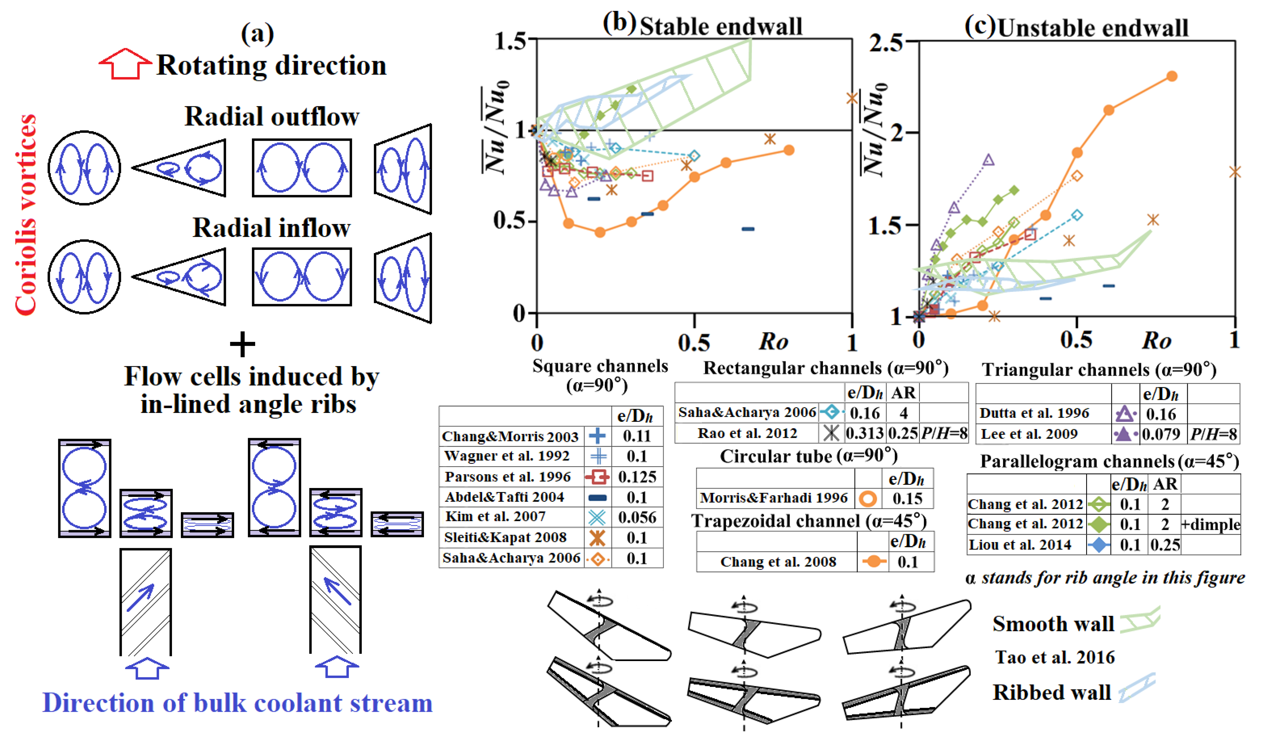
Figure 2. (a) conceptual flow structures on the cross-section of a rotating ribbed coolant channel; variations of endwall-averaged Nu/Nu0 ratio against Ro on (b) stable (c) unstable walls of the rotating ribbed channels with square, circular, trapezoidal, triangular, and parallelogram shapes [17][40][41][42][52][55][56][57][58][59][60][61][62][63][64].
In Figure 2b,c, the variations of the endwall-averaged Nu/Nu0 ratio against Ro on the stable and unstable walls of the rotating ribbed channels with square, circular, trapezoidal, triangular, parallelogram, and irregular (realistic) shapes are compared. The heat transfer data reported in the literature [17][40][42][46][52][55][56][57][58][59][60][61][62][63][64] exhibited a common trend of Ro-driven variations on the stable or unstable channel wall with different Nu/Nu0 ratios. In Figure 2b, the Nu/Nu0 ratios on the stable wall are initially reduced from unity (static-channel reference) and then recovered to be increased with Ro as Ro increases from zero to one. However, the critical Ro, above which the Nu/Nu0 ratio was turned to be increased with Ro, varies with channel sectional shape, rib configurations, and thermal boundary conditions. With Ro in the range of 0.1–0.2, the Nu/Nu0 ratios among the comparative group with different channel shapes in Figure 2b range from 0.5 to 1.02 and require design precautions to avoid overheating spots on the stable wall of a rotating channel. In Figure 2b, the severe heat transfer impediments with the lowest Nu/Nu0 ratio less than 0.5 developed in the rotating trapezoidal channel with angled ribs. Over the unstable wall in Figure 2c, all the Nu/Nu0 ratios the range of 1–2.3 keep increasing with Ro disregarding the sectional shape of the rotating channels. Furthermore, a systematic study aimed at identifying the critical Ro with typical (but realistic) channel configurations is beneficial for designers to parametrically plan the operating conditions of the internal cooling schemes. With the realistic channel shapes for the two-pass smooth and ribbed rotating channels [46], the degrees of heat transfer impediments on the stabilized smooth and ribbed walls in Figure 2b, as well as the heat transfer elevations on the destabilized smooth and ribbed walls in Figure 2c, are not as significant as those generated in the circular, square, rectangular, trapezoidal, and parallelogram channels. The Ro effects on the cooling performances in the rotating two-pass channels with various channel shapes for the inlet and exit passes [46] are comparatively alleviated.
In the coolant channels over the mid-chord region of a gas turbine rotor blade, the ribs and dimples are the most common HTE elements. Figure 3 compares the variations of the Nu/Nu0 ratio against Ro on the rotating, leading, and trailing walls of the rectangular channel (AR = 4) with 45° ribs [19], the rectangular channel (AR = 2) with hemispherical protrusions [35], the rectangular channel (AR = 4) with dimples [36], and the parallelogram channel (AR = 2) with 45° ribs and dimples [41]. The bulk coolant stream in these rotating single-pass channels [19][35][36][41] flow in a radially outward direction. Between the rotating rectangular channels (AR = 4) enhanced by the 45° ribs [19] and dimples with effusion [36] as compared in Figure 3, the Nu/Nu0 ratios on the leading (trailing) wall of the rotating ribbed channel [19] are lower (higher) than their dimpled-channel counterparts [36]. The Ro effects which incurred the respective heat transfer impediments and enhancements on the leading and trailing walls of the rotating ribbed channel were stronger than those in the dimpled channel [36]. While the employment of hemispherical protrusions in the rotating rectangular channel [35] advances the critical Ro from that with the concave dimples [36] to a lower value, which comparatively boosts their Nu/Nu0 levels on both leading and trailing walls from their dimpled-channel counterparts in Figure 3, the compound HTE measure with 45° ribs and dimples in the rotating parallelogram channel [41] can further promote the Nu/Nu0 ratios from those elevated by the hemispherical protrusions [35]. The compound HTE methods involving ribs and concave/convex dimples for promoting the cooling performance of a rotating channel is worthy of future study.
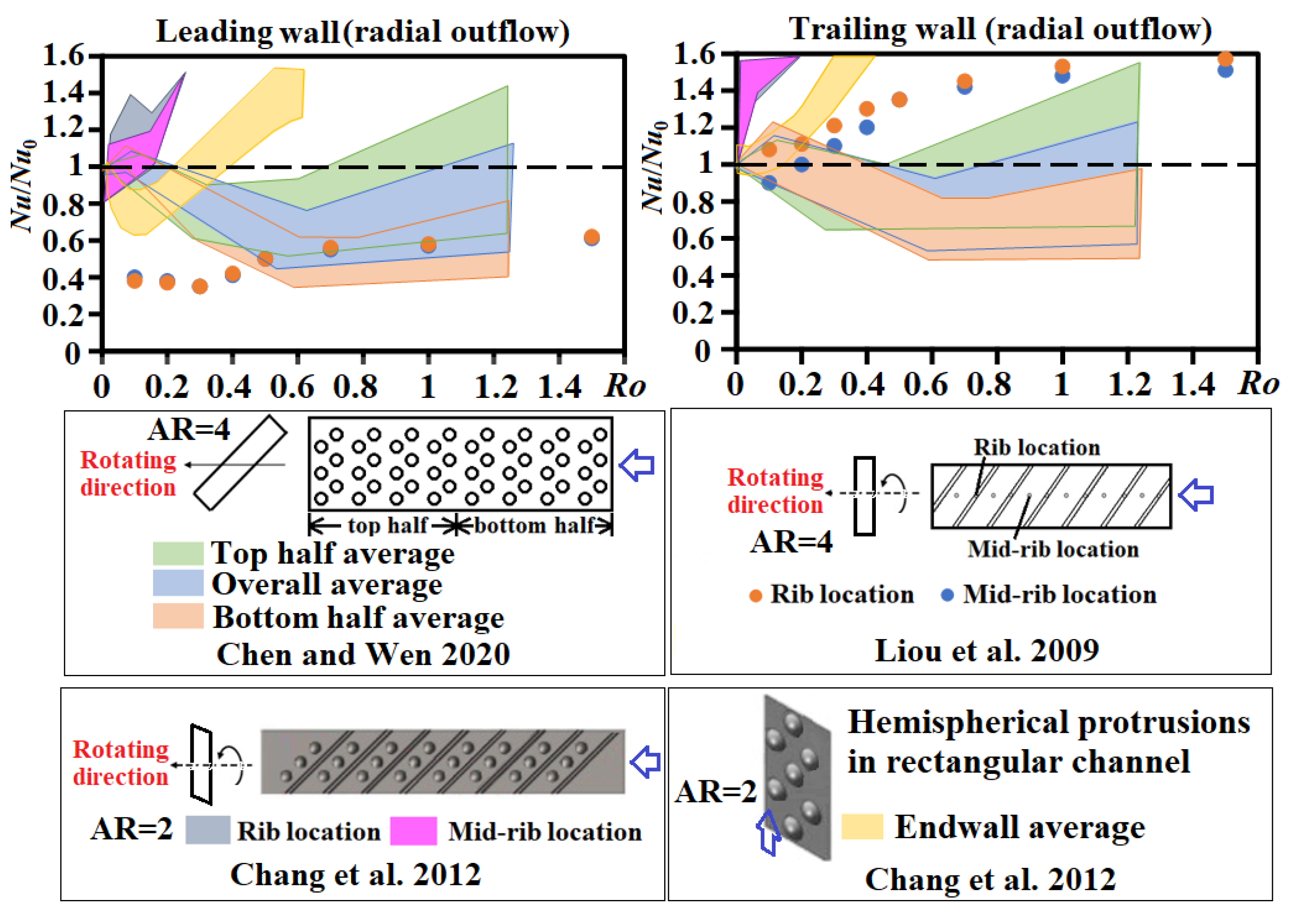
Figure 3. Variations of Nu/Nu0 against Ro on rotating, leading, and trailing walls of rectangular channel (AR = 4) with 45° ribs [19], rectangular channel (AR = 2) with hemispherical protrusions [35], rectangular channel (AR = 4) with dimples [36], and the parallelogram channel (AR = 2) with 45° ribs and dimples [41].
3. Trailing-Edge Cooling
3.1. Smooth-Walled Channel
Wright et al. [65] measured the regionally averaged Nusselt numbers in a wedge-shaped channel with Re, Ro, and Bu in the respective ranges of 10,000–40,000, 0–1.0, and 0–3.5. The spanwise (streamwise) Nu variations on the smooth rotating walls were mainly attributed to the wedge-shaped channel (the sharp entrance and 180° bend). By changing the channel orientation from 0° to 135°, the Nu levels on all rotating walls were increased.
Li et al. [66] proposed a two-inlet, wedge-shaped channel with side-wall ejection for trailing-edge cooling of a gas turbine rotor blade. The mass flow ratio (MR) between the sidewall injection at the channel tip region and the main radial outflow varied from zero to one. The two-inlet inflow promoted (undermined) the local cooling performance over the top-half (bottom-half) endwall portion at Ro = 0. In the rotating channel, the increase in the MR moderated the trailing-to-leading Nu difference due to the two-inlet inflow. This research group also examined the cooling performance of a rotating two-inlet inflow rectangular channel (AR = 4) at an orientation angle of 135° with the MR varying from 0–0.6 [67]. When the MR exceeded a critical value, the Nusselt numbers on the leading wall of the rotating channel were higher than those on the trailing wall. A higher critical MR in the rotating channel was found owing to the suppressed radial inflow by rotation. For the wedge-shaped, two-inlet, smooth-walled channel, the sidewall coolant injection at the channel tip provided the optimal cooling performance in static and rotating conditions [68]. When the eight lateral coolant injections were distributed with an equal interval along the supplementary inflow channels at Ro up to 1.1 [69], the increase in the MR promoted (weakened) cooling effectiveness over the top-half (bottom-half) endwall regions. With an MR > 0.5, the Ro-induced overall heat transfer variations became less than 6%.
3.2. Pin Fin Channel
Chang et al. [70] measured the centerline Nu profiles on the leading and trailing walls of a radially rotating pin fin channel at Ro in the range of 0–1.4. While the Nu on the trailing endwall kept increasing with Ro, the leading Nu was initially reduced from Nu0 as Ro increased from 0 to 0.1, above which the Nu level turned to increase with Ro. With the Coriolis forces directing toward the trailing wall, the pin fin tripped vortices were attached firmly on the trailing wall but lifted from the leading wall to incur the trailing-to-leading Nu reduction at each measured channel section. The worst cooling conditions of the rotating channel emerged on the leading wall with the minimum Nu/Nu0 ratios down to 0.89 and 0.8 at the locations behind and in front of the pin row, respectively. Park et al. [71] used the naphthalene sublimation technique to detect the endwall heat/mass transfer maps for the rotating rectangular channel with inclined pin fins at Ro up to 0.2. It was concluded that the inclined pin fin array from the vertical orientation to a channel wall always deteriorated its heat/mass transfer effectiveness, which was approximately 15% at the inclined angle of 60° in both stationary and rotating conditions. While the rotation levels at Ro = 0.2 exhibited a limited rotational effect, the rotation generally rendered an overall Nu elevation from Nu0. Chang et al. [72] measured the endwall Nu maps on leading and trailing walls of a rotating rectangular channel enhanced by the diamond-shaped pin fin array with radial outflow at Ro and Bu in the respective ranges of 0–0.6 and 0–0.31. The combined Ro and Bu effects qualitatively followed the typical results for a rotating single-pass channel that resulted in the average Nu/Nu0 ratios on the leading (trailing) endwall to the ranges of 0.82–1.52 (1–1.89). In comparison with the heat transfer data generated from the similar rotating channel with circular pin fins, the isolated Ro effect on the leading Nu/Nu0 ratios with the circular and diamond-shaped pin fins remained similar but exhibited a lesser degree of HTE benefits compared with the Coriolis force effects on the trailing wall in the rotating channel with diamond-shaped pin fins. As a pin fin array in a channel considerably disrupted the development of the sectional vortices to alleviate the fluid mixings, Chang and Hu [73] extend the rib land to permit the embodiment of a pin row with a skewed rib. The interaction between the rib-induced vortical flows and the vortex system tripped by the pin fins generated a high Nu0 ring around the slender pin fin that superimposed on the Nu0 map with rib-wise heat transfer decay to signify its endwall heat transfer characteristic. The ratios of Nu0/Nu∞ reached 6.1–5 with 5000 ≤ Re ≤ 15,000. The isolated Coriolis force effects at Ro ≤ 0.4 led the leading (trailing) Nu/Nu0 ratios to become 0.93–1.23 (1–1.28) with the Bu effect to promote the local cooling effectiveness on both leading and trailing endwalls.
Huang et al. [74] adopted the liquid crystal and stroboscopic method to measure the Nu map on the leading and trailing endwalls of the rotating rectangular channel (AR = 4) with the staggered or inline pin fin array at 5000 ≤ Re ≤ 20,000 and 0 ≤ Ro ≤ 0.52. Without rotation, the overall heat transfer rate promoted by the staggered array was 25–30% higher than that of the inline pin fin array. The overall heat transfer enhancements caused by rotation were 22% and 93% for the staggered and inline pin fin arrays, respectively, suggesting the secondary flows induced by the pin fin played a dominant role for the staggered array. Liu group [75] subsequently examined the effect of channel orientation on the cooling performance of the rotating rectangular pin fin channel. At the channel orientation angle of 150°, a larger spanwise Nu variation was resolved due to the deformed Coriolis vortices. At the channel orientation angle of 90°, the inline pin fin array generated the largest Ro-induced HTE effect. When the staggered pin fin array was composed by the non-uniform sizes of circular pins at a channel orientation of 135° [76], the higher local fluid velocities through the fin spaces among the pin fin array composed by the large sized pins promoted local convective flow and hence local Nu. Furthermore, the friction factor increased with the size of the pin fins.
Du et al. [77] numerically examined the heat transfer and flow characteristics in a single-pass rotating rectangular pin fin channel with different dimple locations. Behind the pin row, a counter-rotating vortex was induced by the Coriolis force to convect wakes from trailing-to-leading endwalls. By shifting dimples close to the leading edge of pin rows, the endwall Nu were increased. While the trailing Nu was consistently higher than the leading counterpart, the average Nu on both leading and trailing walls were increased with Ro. Luo et al. [78] numerically explored the effects of convergence angle and dimple shape on the flow structure and cooling performance of a wedge-shaped rotating pin fin channel. The cooling performance of the dimple-pin wedge channel with radial outflow was improved by Ro and/or by increasing its convergence. With a converging angle of 12.7°, the strong downwash flow squeezed by its opposite converging endwall elevated the leading-wall Nu from that of the trailing dimpled endwall. With such strong downwash flow, the Coriolis force effect was alleviated. The amplified turbulent kinetic energy in the vicinity of the dimple with the stronger vortex tripped by the spanwise-elliptical dimples generated a higher HTE effectiveness. Li et al. [79] investigated the combined effect of two inlets and pin fins on the cooling performance of a rotating wedge-shaped channel with radial outflow. With rotation and MR above a critical ratio, the Ro effect was diminished so that the Ro effect was suppressed by the lateral entry flow stream. At a low MR with the radial outflow to dominate the cooling performance of the rotating channel, the heat transfer rate at a channel orientation angle of 135° was less than that at 90°. For such two-inlet rotating pin fin channels, the Ro effect on average heat transfer properties was sensitive to channel orientation rather than the channel shape or pin fins.
Liang and Rao [80] numerically studied the effect of pin fin compositions, which involved detached pins, on flow and heat transfer characteristics of a static and rotating rectangular channel at Ro = 0.15. With detached pins in a pin fin array, the flow above the top face of each detached pin generated the additional transverse vortices in the wake zone behind the pin to promote the local heat transfer rate on the endwall behind the detached pin and improve heat transfer uniformity. With the reduced (increased) friction factors (overall Nu) by 31.9% (16.9%), the thermal performance parameters were raised up to 29.1% compared to those with full-height pin fins. Yan et al. [81] comparatively examined the HTE effectiveness of upright/curved/inclined pin fins in the rectangular channel (AR = 0.7) with Ro varying from 0 to 0.5. With rotation, the HTE performance with the curved pin fins was insensitivity to Ro compared to the other two types of pin fins. On the trailing wall of the rotating channel, a strong pressure gradient close to the pin induced the longitudinal secondary flows behind pin fins to elevate the Nu/Nu0 ratio, which was increased with Ro.
Madhavan et al. [82] measured the Nu maps on the leading and trailing walls of a rotating coolant channel that covered both the mid-chord region and trailing edge of a gas turbine rotor blade. The coolant after entering the 2:1 rectangular ribbed channel was reformed into the crossover jets into the 4:1 trapezoidal pin fin channel with lateral discharge. The lateral jet impingement into the pin fin array promoted fluid mixings in the trailing-edge coolant channel. At Ro = 0.1, the channel-averaged Nu on trailing was approximately 28% and 7.6% higher than their leading counterpart in the ribbed and pin fin passes, respectively. Liang et al. [83] carried out an experimental and numerical study to explore the flow and heat transfer characteristics in a rotating wedge-shaped channel with the innovative guiding pin fin arrays. The endwall-averaged Nu promoted by the guiding pin fin arrays was approximately 33.7% (23%) higher than those with a circular pin fin array in static (rotating) conditions. With the guiding pin fin arrays at Ro = 0.46, the trailing-to-leading Nu difference was considerably alleviated from those with a circular pin fin array, leading to improved heat transfer uniformity. Zhang et al. [84] examined the heat transfer characteristics in a rotating trapezoidal pin fin channel with lateral flow exits at Re and Ro in the respective ranges of 10,000–110,000 and 0–0.5. At a fixed Ro with different rotating speeds, the heat transfer results at a high Re were similar to those at a low Re. The critical Ro above which the Nu/Nu0 on the leading wall turned to be increased with Ro varied with the radial location in the rotating pin fin channel.
3.3. Dimpled Channel
Jing et al. [85] numerically examined the effects of Ro, dimple arrangement, and channel orientation on the flow and heat transfer characteristics of rotating trapezoidal channels with lateral coolant discharge. The cooling performance of the rotating wedge-shaped channel was considerably improved by dimples. A maximum 108.2% Nu improvement on the trailing wall of the rotating dimpled channel was achieved by increasing Ro. Chen et al. [86] experimentally explored the heat transfer characteristics of a rotating trailing-edge coolant channel with pin fins and dimples at Re, Ro, and Bu in the respective ranges of 12,000–20,000, 0–0.89, and 0–1.32. The high HTE region on the tip region of the endwall was contracted by rotation. The endwall subjected to heat transfer reduction was expanded in radially inward direction with Ro. The Bu effect impaired (promoted) heat transfer rates at low (high) Ro. In view of the coupled and isolated Ro and Bu effects, the governing dimensionless flow parameters evaluated at local values were more instructive than those defined by flow entry conditions.
3.4. Latticework Channel
Oh et al. [87] investigated the heat/mass transfer and pressure drop characteristics in a matrix cooling channel at Ro in the range of 0–0.8. The flow complexities induced in the static matrix channel raised the endwall average heat/mass transfer rates to approximately 2.1 times greater than those in a likewise smooth channel. As Ro increased, the Sherwood number ratios on the leading wall also increased but altered slightly on the trailing wall, whereas the f/f0 ratios decreased with Ro, leading to increased thermal performance factors. Du et al. [88] numerically examined the effect of broken rib locations on the flow and heat transfer characteristics of a rotating latticework channel with radial outflow. The flow characteristic was dominant by the induced upward spiral and helical flows among the lattice maze with local flow impingement induced by the upward spiral flow to promote local heat transfer rate and wall shear stress. Using the broken skew ribs to configure the latticework, the average Nu was elevated by 6.12% (6.02%) on the trailing (ribbed) endwall compared to those with conventional latticework. The Nu/Nu0 ratio was decreased with Ro by up to 5.4% over the trailing (pressure) wall. Heat transfer elevations on the leading (suction) wall emerged at high Ro at which the friction factors were reduced, leading to an increase in the thermal performance factor by 12.12% using the broken ribs.
This entry is adapted from the peer-reviewed paper https://doi.org/10.3390/inventions8010021
References
- Hsieh, S.S.; Tsai, H.-H.; Chan, S.-C. Local heat transfer in rotating square-rib-roughened and smooth channels with jet impingement. Int. J. Heat Mass Transf. 2004, 47, 2769–2784.
- Adreini, A.; Brberi, E.; Cocchi, L.; Facchini, B.; Massini, D.; Pievaroli, M. Heat transfer investigation on an internal cooling system of a gas turbine leading edge model. Energy Procedia 2015, 82, 222–229.
- Cocchi, L.; Facchini, B.; Picchi, A. Heat transfer measurements in leading-edge cooling geometry under rotating conditions. J. Thermophys. Heat Transf. 2019, 33, 844–855.
- Furlani, L.; Armellini, A.; Casarsa, L. Rotational effects on the flow field inside a leading edge impingement cooling passage. Exp. Therm. Fluid Sci. 2016, 76, 57–66.
- Elston, C.A.; Wright, L.M. Leading edge jet impingement under high rotation numbers. ASME Trans. J. Therm. Sci. Eng. Appl. 2017, 9, 021010.
- Singh, P.; Ekkad, S.V. Detailed heat transfer measurements of jet impingement on dimpled target surface under rotation. ASME Trans. J. Therm. Sci. Eng. Appl. 2018, 10, 031006.
- Chang, S.W.; Yu, K.-C. Thermal performance of radially rotating trapezoidal channel with impinging jet-row. Int. J. Heat Mass Transf. 2019, 136, 246–264.
- Wang, J.; Deng, H.; Tao, Z.; Li, Y.; Zhu, J. Heat transfer in a rotating rectangular channel with impingement jet and film holes. Int. J. Therm. Sci. 2021, 163, 106832.
- Deng, H.; Wang, Z.; Wang, J.; Li, H. Flow and heat transfer in a rotating channel with impingement cooling and film extraction. Int. J. Heat Mass Transf. 2021, 180, 121751.
- Li, H.; Deng, H.; Qiu, L. Effect of channel orientation on heat transfer in a rotating impingement cooling channel. Int. J. Heat Mass Transf. 2022, 187, 122493.
- Gleze, B.; Moon, H.K.; Kerrebrock, J.; Bons, J.; Guenette, G. Heat transfer in a rotating radial channel with swirling internal flow. Int. Gas Turbine Aeroengine Congr. Exhib. 1998, 98-GT-214, 1–7.
- Rao, Y.; Biegger, C.; Weigand, B. Heat transfer and pressure loss in swirl tubes with one and multiple tangential jets pertinent to gas turbine internal cooling. Int. J. Heat Mass Transf. 2017, 106, 1356–1367.
- Wang, J.; Liu, J.; Wang, L.; Sundén, B.; Wang, S. Conjugated heat transfer investigation with racetrack-shaped jet hole and double swirling chamber in rotating jet impingement. Numer. Heat Transf. Part A Appl. 2018, 73, 768–787.
- Tansakul, P.; Thawornsathit, P.; Juntasaro, V.; Juntasaro, E. Buoyancy effect on leading edge cooling of a rotating turbine blade. Trans. ASME J. Therm. Sci. Eng. Appl. 2022, 14, 111015.
- Chang, S.W.; Yang, T.L.; Wang, W.J. Heat transfer in a rotating twin-pass trapezoidal-sectioned passage roughened by skewed ribs on two opposite walls. J. Heat Transf. Eng. 2006, 27, 63–79.
- Guo, X.; Xu, H.; Li, X.; Ren, J. Flow and heat transfer characteristics of Coriolis-utilization rotating rectangular smooth cooling U-channel. Appl. Therm. Eng. 2022, 211, 118420.
- Chang, S.W.; Morris, W.D. Heat transfer in a radially rotating square duct fitted with in-line transverse. Int. J. Therm. Sci. Ribs 2003, 42, 267–282.
- Su, G.; Chen, H.-C.; Han, J.-C.; Heidmann, J.D. Computation of flow and heat transfer in rotating two-pass rectangular channels (AR = 1:1, 1:2, and 1:4) with smooth wall by a Reynolds stress turbulence model. Int. J. Heat Mass Transf. 2004, 47, 5665–5683.
- Liou, T.-M.; Chang, S.W.; Chen, J.S.; Yang, T.L.; Lan, Y.-A. Influence of channel aspect ratio on heat transfer in rotating rectangular ducts with skewed ribs at high rotation numbers. Int. J. Heat. Mass Transf. 2009, 52, 5309–5322.
- Murata, A.; Mochizuki, S. Large eddy simulation with a dynamic subgrid-scale model of turbulent heat transfer in an orthogonally rotating rectangular duct with transverse rib turbulators. Int. J. Heat Mass Transf. 2000, 43, 1243–1259.
- Murata, A.; Mochizuki, S. Effect of cross-sectioned aspect ratio on turbulent heat transfer in an orthogonally rotating rectangular duct with angled rib turbulators. Int. J. Heat Mass Transf. 2003, 46, 3119–3133.
- Kim, K.M.; Kim, Y.Y.; Lee, D.H.; Rhee, D.H.; Cho, H.H. Influence of duct aspect ratio on heat/mass transfer in coolant passages with rotation. Int. J. Heat Fluid Flow 2007, 28, 357–373.
- Chang, S.W.; Lees, A.W.; Liou, T.-M.; Hong, G.F. Heat transfer of a radially rotating furrowed channel with two opposite skewed sinusoidal wavy walls. Int. J. Therm. Sci. 2010, 49, 769–785.
- Chang, S.W.; Liou, T.-M.; Po, Y. Coriolis and rotating buoyancy effect on detailed heat transfer distributions in a two-pass square channel roughened by 45° ribs at high rotation numbers. Int. J. Heat Mass Transf. 2010, 53, 1349–1363.
- Mayo, I.; Arts, T.; El-Habib, A.; Parres, B. Two-dimensional heat transfer distribution of a rotating ribbed channel at different Reynolds numbers. ASME Trans. J. Turbomach. 2015, 137, 031002.
- Xu, G.; Li, Y.; Deng, H. Effect of rib spacing on heat transfer and friction in a rotating two-pass square channel with asymmetrical 90-deg rib turbulators. Appl. Therm. Eng. 2015, 80, 386–395.
- Wang, Z.; Corral, R. Effect of uneven wall heating conditions under different buoyancy numbers for a one side rib-roughened rotating channel. ASME Trans. J. Turbomach. 2017, 139, 111011.
- Deng, H.; Li, Y.; Tao, Z.; Xu, G.; Tian, S. Pressure drop and heat transfer performance in a rotating two-pass channel with staggered 45-deg ribs. Int. J. Heat Mass Transf. 2017, 108, 2273–2282.
- Singh, P.; Li, W.; Ekkad, S.V.; Ren, J. A new cooling design for rib roughened two-pass channel having positive effects of rotation on heat transfer enhancement on both pressure and suction side internal walls of a gas turbine blade. Int. J. Heat Mass Transf. 2017, 115, 6–20.
- Wang, J.; Liu, J.; Wang, L.; Sunden, B.; Wang, S. Numerical investigation of heat transfer and fluid flow in a rotating rectangular channel with variously discrete ribs. Appl. Therm. Eng. 2018, 129, 1369–1381.
- Yan, H.; Luo, L.; Sun, P.; Du, W.; Wang, S.; Huang, D. Combined effects of bleed hole extraction and rotation on internal heat transfer in a ribbed two-pass channel. Int. Commun. Heat Mass Transf. 2022, 133, 105964.
- Li, H.-L.; Chiang, H.-W.D.; Hsu, C.N. Jet impingement and forced convection cooling experimental study in rotating turbine blades. Int. J. Turbo Jet Engines 2011, 28, 147–158.
- Kim, S.; Choi, E.Y.; Kwak, J.S. Effect of channel orientation on the heat transfer coefficient in the smooth and dimpled rotating rectangular channels. ASME Trans. J. Heat Transf. 2012, 134, 064504.
- Lamont, J.A.; Ekkad, S.V.; Alvin, M.A. Effects of rotation on heat transfer for a single row jet impingement array with crossflow. ASME Trans. J. Heat Transf. 2012, 134, 082202.
- Chang, S.W.; Liou, T.-M.; Chen, W.-C. Influence of radial rotation on heat transfer in a rectangular channel with two opposite walls roughened by hemispherical protrusions at high rotation numbers. ASME Trans. J. Turbomach. 2012, 134, 011010.
- Xu, G.; Chen, Y.; Wen, J. Heat transfer in a rotating rectangular channel (AR=4) with dimples and sidewall bleeds. Int. J. Heat Mass Transf. 2020, 150, 119118.
- Chang, S.W.; Wu, P.-S.; Chen, C.-S.; Weng, C.-C.; Jiang, Y.-R.; Shihe, S.-H. Thermal performance of radially rotating two-pass S-shaped zig-zag channel. Int. J. Heat Mass Transf. 2017, 115, 1011–1031.
- Siw, S.C.; Chyu, M.K.; Alvin, M.A. Heat transfer and pressure loss characteristics of zig-zag channel with rib-turbulators. ASME Turbo Expo 2013, GT2013-95407, 1–10.
- Chang, S.W.; Huang, S.-W. Aerothermal performance of a rotating two-pass furrowed channel roughened by angled ribs. Appl. Therm. Eng. 2021, 199, 117613.
- Dutta, S.; Han, J.C.; Lee, C.P. Local heat transfer in a rotating two-pass ribbed triangular duct with two model orientations. Int. J. Heat Mass Transf. 1996, 39, 707–715.
- Chang, S.W.; Liou, T.-M.; Lee, T.-H. Thermal performance comparison between radially rotating ribbed parallelogram channels with and without dimples. Int. J Heat Mass Transf. 2012, 55, 3541–3559.
- Liou, T.-M.; Chang, S.W.; Yang, C.-C. Heat transfer and pressure drop measurements of rotating twin-pass parallelogram ribbed channel. Int. J. Therm. Sci. 2014, 79, 206–219.
- Liou, T.-M.; Chang, S.W.; Lan, Y.-A.; Chan, S.-P. Isolated and coupled effects of rotating and buoyancy number on heat transfer and pressure drop in a rotating two-pass parallelogram channel with transverse ribs. ASME Trans. J. Heat Transf. 2018, 140, 032001.
- Brahim, B.; Miloud, A. Numerical simulation of the effect of channel orientation on fluid flow and heat transfer at high buoyancy number in a rotating two-pass channel with angled ribs. ASME Trans. J. Heat Transf. 2019, 141, 022502.
- Li, H.; You, R.; Deng, H.; Tao, Z.; Zhu, J. Heat transfer investigation in a rotating U-turn smooth channel with irregular cross-section. Int. J. Heat Mass Transf. 2016, 96, 267–277.
- Tao, Z.; Yang, M.; Deng, H.; Li, H.; Tian, S. Heat transfer study in a rotating ribbed two-pass channel with engine-similar cross section at high rotation number. Appl. Therm. Eng. 2016, 106, 681–696.
- Chen, A.F.; Wu, H.-W.; Wang, N.; Han, J.-C. Heat transfer in a rotating cooling channel (AR = 2:1) with rib turbulators and a tip turning vane. ASME Trans. J. Heat Transf. 2018, 140, 102007.
- Chen, A.F.; Shiau, C.-C.; Han, J.-C.; Krewinkel, R. Heat transfer in a rotating two-pass rectangular channel featuring reduced cross-sectional area after tip turn (aspect ratio = 4:1 to 2:1) with profiled 60 deg angled ribs. ASME Trans. J. Turbomach. 2019, 141, 071008.
- Sahin, I.; Chen, A.F.; Shiau, C.-C.; Han, J.-C.; Krewinkel, R. Effect of 45-deg rib orientations on heat transfer in a rotating two-pass channel with aspect ratio from 4:1 to 2:1. ASME Trans. J. Turbomach. 2020, 142, 071003.
- Chen, I.-L.; Sahin, I.; Wright, L.M.; Han, J.-C.; Krewinkel, R. Heat transfer in a rotating, two-pass, variable aspect ratio cooling channel with profiled V-shaped ribs. ASME Trans. J. Turbomach. 2021, 143, 081013.
- Wagner, J.H.; Johnson, B.V.; Kopper, F.C. Heat transfer in rotating serpentine passages with smooth walls. Trans. ASME J. Turbomach. 1991, 113, 321–330.
- Wagner, J.H.; Johnson, B.V.; Graziani, R.A.; Yeh, F.C. Heat transfer in rotating serpentine passages with trips normal to the flow. Trans. ASME J. Turbomach. 1992, 114, 847–857.
- Johnson, B.V.; Wagner, J.H.; Steuber, G.D.; Yeh, F.C. Heat transfer in rotating serpentine passages with trips skewed to the flow. Trans. ASME J. Turbomach. 1994, 116, 113–123.
- Amagasa, S.; Shimomura, K.; Kadowaki, M.; Takeishi, K.; Kawai, H. Study on the turbine vane and blade from a 1500 °C class industrial gas turbine. Trans. ASME J. Eng. Gas Turbine Power 1994, 116, 591–604.
- Parsons, J.A.; Han, J.-C.; Zhang, Y. Wall heating effect on local heat transfer in a rotating two-pass square channel with 90° rib turbulators. Int. J. Heat Mass Transf. 1996, 37, 1411–1420.
- Abdel-Wahab, S.; Tafti, D.K. Large eddy simulation of flow and heat transfer in a 90 deg ribbed duct with rotation: Effect of Coriolis and centrifugal buoyancy forces. ASME Trans. J. Turbomach. 2004, 126, 627–636.
- Kim, K.M.; Lee, D.H.; Cho, H.H. Detailed measurement of heat/mass transfer and pressure drop in a rotating two-pass duct with transverse ribs. Heat Mass Transf. 2007, 43, 801–815.
- Sleiti, A.K.; Kapat, J.S. Effect of Coriolis and centrifugal forces on turbulence and transport at high rotation and density ratios in a rib-roughened channel. Int. J. Therm. Sci. 2008, 47, 609–619.
- Saha, A.K.; Acharya, S. Turbulent heat transfer in ribbed coolant passages of different aspect ratios: Parametric effects. Int. J. Heat Mass Transf. 2006, 129, 449–463.
- Morris, W.D.; Farhadi, R.-A.K. Convective heat transfer in rotating ribbed tubes. Int. J. Heat Mass Transf. 1996, 39, 2253–2266.
- Chang, S.W.; Liou, T.-M.; Chiou, S.F.; Chang, S.F. Heat transfer in high-speed rotating trapezoidal duct with rib-roughened surfaces and air bleeds from the wall on apical side. Int. J. Heat Mass Transf. 2008, 130, 061702.
- Lee, D.H.; Rhee, D.H.; Kim, K.M.; Cho, H.H.; Moon, H.K. Heat transfer and flow temperature measurements in a rotating triangular channel with various rib arrangements. Heat Mass Transf. 2009, 45, 1543–1553.
- Chang, S.W.; Liou, T.-M.; Lee, T.H. Thermal performance of developing flow in a radially rotating parallelogram channel with 45° ribs. Int. J. Therm. Sci. 2012, 52, 186–204.
- Rao, Y.; Wan, C.; Xu, Y. An experimental study of pressure loss and heat transfer in the d channels with various dimple depths. Int. J. Heat Mass Transf. 2012, 55, 6723–6733.
- Wright, L.M.; Liu, Y.-H.; Han, J.-C.; Chopra, S. Heat transfer in trailing edge, wedge-shaped cooling channels under high rotation numbers. ASME Trans. J. Heat Transf. 2008, 130, 071701.
- Li, Y.; Deng, H.; Tao, Z.; Xu, G.; Chen, Y. Heat transfer characteristics in a rotating trailing edge internal cooling channel with two coolant inlets. Int. J. Heat Mass Transf. 2017, 105, 220–229.
- Deng, H.; Chen, Y.; Tao, Z.; Li, Y.; Qiu, L. Heat transfer in a two-inlet rotating rectangular channel with side-wall fluid extraction. Int. J. Heat Mass Transf. 2017, 105, 525–534.
- Deng, H.; Cheng, Y.; Li, Y.; Li, B.; Qiu, L. Heat transfer in a two-inlet rotating wedge-shaped channel with various locations of the second inlet. Int. J. Heat Mass Transf. 2017, 106, 25–34.
- Deng, H.; Li, L.; Zhu, J.; Tao, Z.; Tian, S.; Yang, Z. Heat transfer of a rotating two-inlet trailing edge channel with lateral fluid extractions. Int. J. Therm. Sci. 2018, 125, 313–323.
- Chang, S.W.; Liou, T.-M.; Yang, T.L.; Hong, G.F. Heat transfer in radially rotating pin-fin channel at high rotation numbers. ASME Trans. J. Turbomach. 2010, 132, 021019.
- Park, J.S.; Kim, K.M.; Lee, D.H.; Cho, H.H.; Chyu, M. Heat transfer in rotating channel with inclined pin-fins. ASME Trans. J. Turbomach. 2011, 133, 021003.
- Chang, S.W.; Liou, T.-M.; Lee, T.-H. Heat transfer of a rotating rectangular channel with a diamond-shaped pin-fin array at high rotation numbers. ASME Trans. Turbomach. 2013, 135, 041007.
- Chang, S.W.; Hu, Y.-W. Endwall thermal performances of radially rotating rectangular channel with pin-fins on skewed rib lands. Int. J. Heat Mass Transf. 2014, 69, 173–190.
- Huang, S.-C.; Wang, C.-C.; Liu, Y.-H. Heat transfer measurement in a rotating cooling channel with staggered and inlined pin-fin array using liquid crystal and stroboscopy. Int. J. Heat Mass Transf. 2017, 115, 364–376.
- Huang, S.C.; Wang, C.-C.; Liu, Y.-H. Channel orientation effect on endwall heat transfer in rotating passages with pin-fins. Int. J. Heat Mass Transf. 2019, 136, 1115–1126.
- Hung, S.-C.; Huang, S.-C.; Liu, Y.-H. Effect of nonuniform pin size on heat transfer in a rotating rectangular channel with pin-fin arrays. Appl. Therm. Eng. 2019, 163, 114393.
- Du, W.; Luo, L.; Wang, S.; Zhang, X. Effect of the dimple location and rotating number on the heat transfer and flow structure in a pin finned channel. Int. J. Heat Mass Transf. 2018, 127, 111–129.
- Luo, L.; Yan, H.; Yang, S.; Du, W.; Wang, S.; Sunden, B.; Zhang, X. Convergence angle and dimple shape effects on the heat transfer characteristics in a rotating dimple-pin fin wedge duct. Numer. Heat Transf. Part A 2018, 74, 1611–1635.
- Li, H.; Deng, H.; Bai, L.; Zhu, J.; Tian, S.; Qiu, L. Heat transfer in a rotating two-inlet wedge-shaped channel with pin-fins. Int. J. Heat Mass Transf. 2020, 163, 120380.
- Liang, C.; Rao, Y. Numerical study of turbulent flow and heat transfer in channels with detached pin fin arrays under stationary and rotating conditions. Int. J. Therm. Sci. 2021, 160, 106659.
- Yan, H.; Luo, L.; Zhang, J.; Du, W.; Wang, S.; Huang, D. Flow structure and heat transfer characteristics of a pin-finned channel with upright/curved/inclined pin fins under stationary and rotating conditions. Int. Commun. Heat Mass Transf. 2021, 127, 105483.
- Madhavan, S.; Singh, P.; Ekkad, S. Effect of rotation on heat transfer in AR = 2:1 and AR = 4:1 channels connected by a series of crossover jets. ASME Trans. J. Turbomach. 2022, 144, 061011.
- Liang, C.; Rao, Y.; Chen, J.; Zhang, P. Experimental and numerical study of the turbulent flow and heat transfer in a wedge-shaped channel with guiding pin fin arrays under rotating conditions. ASME Trans. J. Turbomach. 2022, 144, 071007.
- Zhang, X.; Li, H.; Tian, Y.; You, R.; Zhang, D.; Wu, A. Heat transfer in a rotating lateral outflow trapezoidal channel with pin fins under high rotation numbers and Reynolds numbers. Appl. Therm. Eng. 2022, 213, 118725.
- Jing, Q.; Xie, Y.; Zhang, D. Numerical investigation of flow and heat transfer in rotating trapezoidal channel with lateral slots and dimple structure. Int. Commun. Heat Mass Transf. 2020, 118, 104865.
- Chen, Y.; Xu, G.; Wen, J.; Zhu, C. Rotational heat transfer in a rectangular cooling channel with compound turbulators of pin-fins and dimples. Int. J. Heat Mass Transf. 2022, 184, 121897.
- Oh, I.T.; Kim, K.M.; Lee, D.H.; Park, J.S.; Cho, H.H. Local heat/mass transfer and friction loss measurement in a rotating matrix cooling channel. ASME Trans. J. Heat Transf. 2012, 134, 011901.
- Du, W.; Luo, L.; Wang, S.; Liu, J.; Sunden, B. Effect of the broken rib locations on the heat transfer and fluid flow in a rotating latticework duct. ASME Trans. J. Heat Transf. 2019, 141, 102102.
This entry is offline, you can click here to edit this entry!