Your browser does not fully support modern features. Please upgrade for a smoother experience.
Please note this is an old version of this entry, which may differ significantly from the current revision.
Subjects:
Engineering, Petroleum
Shale oil resources are important supplements for the gradually decreasing oil production from conventional reservoirs. The exploitation and development of shale oil have achieved considerable progress, the commercial extraction of hydrocarbons from shales is still difficult, especially in the lacustrine sedimentary basins of China.
- shale oil
- occurrence space
- occurrence state
1. Introduction
One of the most significant achievements in fossil fuels in the last decade is the commercial extraction of hydrocarbons from unconventional shale reservoirs. In 2019, the total crude oil production in the U.S. reached 609 million tons, of which 65% was produced from tight shales [1]. Crude oil production has doubled since 2010 in the U.S., primarily driven by the effective development of tight shale systems using horizontal drilling and hydraulic fracturing. In fact, shale systems have been ignored for a long time, and regarded only as source rocks of hydrocarbons throughout history. The retained hydrocarbons in shales were unappreciated until advanced drilling and completion technologies were applied to economically extract oil and gas [2]. Currently, unconventional shales have received new attention in petroleum generation, retention, migration, and accumulation for academic and industrial researchers around the world.
The effective developments of liquid hydrocarbons have been successfully achieved in a lot of shale systems in North America, including the Wolfcamp shales in the Permian Basin [3], Eagle Ford shales in southern Texas [4], Bakken shale formations in the Williston Basin [5], etc. Shale oil formations in North America were mainly deposited in marine sedimentary basins. The organic matter of these shales is at a high thermal maturity stage. These shales are also characterized by high light hydrocarbons content and movable oil content. Meanwhile, there are also considerable shale oil resources in China, including the Triassic Yanchang Formation in the Ordos Basin [6], the Cretaceous Qingshankou Formation in the Songliao Basin [7], the Permian Lucaogou Formation in the Santanghu Basin, and the Palaeogene Shahejie Formation in Bohai Bay Basin [8], etc. Unlike the marine sedimentary basins, shale oil formations in China were mainly deposited in lacustrine sedimentary environments [9]. Lacustrine shales are characterized as strongly heterogeneous in fabric, texture, and mineralogy. Shale oil extracted from the lacustrine source rocks commonly contains more asphaltene and resin content [10]. Thus, lacustrine shale oil is less movable compared to shales from marine sedimentary basins. Operators drilled many wells in lacustrine shale formations but did not always achieve satisfactory results. For example, the initial yield of the BY1 well, drilled in the first demonstration plot of China, was about 8.22 m3/d after hydraulic fracturing and quickly decreased to 1.6 m3/d [11]. Oil production from the HF1 well, drilled in the first breakthrough plot of lacustrine shale oil in China, was 23.6 m3/d initially and soon decreased to about 1 m3/d [12]. Thus, the effective development of shale oil in China is fairly difficult considering the severe reservoir heterogeneity and low flow ability of hydrocarbons [13]. The limited production of lacustrine shale oil is probably related to the poor understanding of petroleum generation and retention in shale systems [14].
Compared to conventional reservoirs, shales are much tighter with low porosity and ultra-low permeability. Minerals in shales, including organic matter and inorganic matter, are much more fine-grained and diversified. Shale systems are further complicated by the diagenetic transformation of inorganic minerals and hydrocarbons generated from organic matter [14]. Furthermore, the particle size and pores of shales are extremely fine [15]. Consequently, the hydrocarbon generation, expulsion, and retention are significantly different from the conventional reservoirs. Many characterization technologies used in sandstones and carbonates are not applicable to shales [16]. It is challenging to accurately estimate the pore structure, oil content, and oil movability of shale systems.
Previous investigations about shale oil have found that shale oil enrichment in lacustrine basins is affected by the lithofacies, minerals, interlayers, reservoir characteristics (pores, porosity, permeability, fractures), and organic geochemistry properties [17,18,19]. In lacustrine shale systems, laminated shales are thought to be favorable for shale oil accumulation [17]. Liu et al. thought that the laminated siliceous mudstones with moderate total organic carbon (TOC) content have abundant reservoir space and are the most favorable lithofacies for shale oil enrichment [18]. Bai et al. investigated the lacustrine shale oil accumulation in the Bohai Bay Basin and found that the interparticle pores in carbonates act as the reservoir spaces of shale oil [19]. Hu et al. thought that fractures provide oil migration pathways from source rocks to the reservoir, thus the interbedded intervals with abundant fractures are favorable for shale oil accumulation [20]. The fluid movability, abnormal fluid pressure, interlayers, and developed fractures are important to the high production of shale oil. In terms of the occurrence mechanism, molecular simulations have been adopted to analyze the adsorption behavior of shale oil at a micro-scale [21]. The occurrence space of shale oil can be observed by direct imaging techniques. Indirect methods, including nuclear magnetic resonance (NMR) and pyrolysis experiments, are also applied to investigate the occurrence state and content of shale oil [22,23,24]. Rock pyrolysis experiments divide hydrocarbons in shales into free oil and pyrolytic hydrocarbons, taking 300 °C as the boundary [22].
2. The Geological Definition of Shale Oil
2.1. Definition of Shale Oil
Shale oil refers to the non-gaseous hydrocarbons stored in organic-rich shales, mudstones, and their thin interlayers (siltstones, carbonates, etc.) [25]. During the early stage, the definition of shale oil was disputed by many researchers from a couple of different perspectives, including sedimentary lithology, reservoir space, and organic matter characteristics, etc. [26]. The initial definition of shale oil only refers to the oil accumulated in the organic-rich shales and mudstones with self-generated and self-stored characteristics. With the development of unconventional reservoirs, researchers and operators have loosened the definition: shale oil contains the petroleum not only retained in shales but also stored in interlayered tight sandstones and carbonate. In other words, petroleum accumulated in both self-generated self-stored reservoirs and short-distance migrated reservoirs can be ascribed to shale oil. In the “geological evaluation method for shale oil” (GB/T38718-2020) formulated by the standardization administration of China in 2020 [27], shale oil refers to oil stored in organic-rich shale systems with a thickness of fewer than 5 m for each organic-lean interbedded layer and a ratio of less than 30% for the accumulated thickness of the interbedded layers.
2.2. The Occurrence State of Shale Oil
Oil stores in organic-rich shale systems via free, adsorption, and absorption (solvation) states [28]. Free shale oil mainly stores within interlayered fractures, structural fractures, and overpressured fractures [29]. It also occurs as a free state in the recrystallized intercrystalline pores and dissolution-related pores with large pore diameters and forms locally continuous hydrocarbon aggregation [30]. Adsorbed shale oil is mainly associated with organic matter and clay minerals. Because of the van der Waals force and Coulomb force between these minerals and hydrocarbon molecules, oil in the adsorbed state presents with a solid-like form for which flow is difficult [31]. The absorption state of shale oil is that shale oil is dissolved in kerogen, which causes the kerogen to expand.
3. Occurrence Space Characterization of Shale Oil
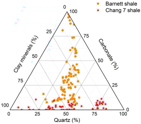
Shale systems are severely heterogeneous. Figure 1 illustrates the mineral compositions of Barnett shale from Fort Worth Basin [30] and Chang 7 shale from Ordos Basin [6]. There is significant variation in mineral compositions of shales, even from the same formation. Shale oil movability is closely related to the minerals, pore structure, pore size distribution, and pore connectivity.
There are several types of micropores and nanopores in shale reservoirs, including organic matter-hosted pores, intergranular pores, dissolution-related pores, and microfractures [32]. Recently, many advanced technologies have been introduced to qualitatively and quantitatively characterize the occurrence space of shale oil. These techniques can be mainly classified into three categories: image observation method, fluid injection method, and high-energy ray method (Figure 2).
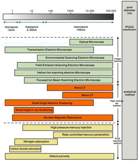
Figure 2. Experimental methods used to characterize the pore structure of shales.
3.1. Image Observation Technology
Image observation is a kind of technology that uses high-resolution imaging technology to directly observe the microscopic pore characteristics of shales. Using advanced imaging instruments, including focused ion beam-scanning electron microscopy (FIB-SEM), field emission-scanning electron microscopy (FE-SEM), atomic force microscopy (AFM), scanning transmission electron microscopy (STEM), helium ion-scanning electron microscopy (HIM), etc., the geometrical morphology of nano-scaled pores in shales can be visually observed. Generally, samples are mechanically polished before image observation. However, the cutting force during mechanical polishing may produce artificial fractures and pores. The abrasive particles used in mechanical polishing also easily occlude pores. Thus, shale samples prepared by mechanical polishing are not always satisfactory for image observation. In order to produce smooth and flat surfaces, Loucks et al. [32] utilized argon ion polishing technology in a metal surface treatment to prepare shale samples and obtained a high-quality sample surface. Combined with scanning electron microscopy, types of nano-scaled pores in organic matter of shales were observed [33,34,35]. Subsequently, argon ion polishing technology has been widely used to prepare shale samples.
For the conventional reservoirs, an optical microscope is feasible to observe their pore structure, with pore diameters being one micrometer or larger. However, the resolution of optical microscopes (about 0.01mm) is not high enough to observe the mineral arrangements and pore morphology of shales. Field emission-scanning electron microscopy (FE-SEM) can acquire images with a high resolution of up to 5 nm. After argon ion polishing, the samples are coated with gold or carbon to increase the conductivity and then used for FE-SEM imaging (Figure 3, [36]). Mastalerz et al. [37] studied the effect of argon ion polishing on shale samples during sample preparation and believed that the organic matter thermal alteration usually involves the volatilization of light hydrocarbon components. Thus, more care should be taken during the polishing of immature samples and oil window samples. With the application of FE-SEM, Wang et al. [38] investigated the pore structure of lacustrine shales in the Ordos Basin and found that hydrocarbon generation, mineral transformation, and compaction affected the evolution of pores.
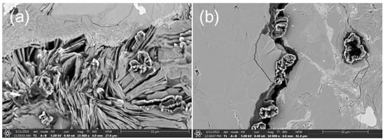
Figure 3. FE-SEM images showing moveable oil spilling from (a) interparticle pores of clay minerals ([modified from Zheng et al. [36]]); (b) microfracture of shales in the Ordos Basin.
Scanning transmission electron microscopy (STEM) scans the sample surface using electron beams and images by electron penetration. Laura constructed the three-dimensional (3D) structure of shales using STEM tomography and found that the nano-scaled pores below 20nm dominate in number but do not form connected pore networks, while the pores with pore sizes between 20nm and 60nm are well connected and therefore controlled the transport property of shales [39].
Focused ion beam-scanning electron microscopy (FIB-SEM) accelerates the ion beam generated by liquid metal (most FIB uses Ga) ion source through an ion gun and strips the surface atoms to complete the micro- and nano-scaled surface topography. Combined with the computer algorithms, FIB-SEM presents the 3D distribution of pores and quantitatively provides the pore structure parameters and pore connectivity [40]. Zhou et al. [41] used FIB-SEM to study the two-dimensional and three-dimensional characteristics of shales from the Longmaxi Formation and calculated pore size distributions of the three-dimensional (3D) digital rock reconstructed from 600 consecutive FIB-SEM images.
Helium ion microscopy (HIM) is a method of imaging samples by accelerating and concentrating helium beams in the sample surface. Compared with electron beams, helium ion beams can better detect the internal structural characteristics of small pores; due to that, coating before electron microscope observation may destroy fine pores. HIM can obtain more reliable images of pores by direct observation without coating. Huang et al. used HIM to study the formation and evolution of organic matter pores in shales [42]. They divided the formation process of organic matter pores into four stages: formation, expansion, connection, and consolidation. King et al. found that organic matter contains an anomalous population of pores of the order ~2 nm [43]. They thought that these narrow pores were produced when the excess internal pressure failed to create escape pathways for the generated fluids during the kerogen diagenesis process.
Atomic force microscopy (AFM) is a scanning probe technology that approaches the sample surface with a highly sensitive probe installed on the cantilever. The interaction force between the needle tip of the probe and the sample surface deforms the cantilever beam. Using the optical leverage principle, the small deformation of the cantilever beam is amplified and converted into electrical signals so as to obtain the surface morphology and roughness information of the sample. The AFM not only produces high-resolution 2D and 3D images, but also characterizes the mechanical properties of the sample, such as Young’s modulus, adhesion force, and electric potential (Figure 4). Javapour et al. [44] used AFM to characterize the surface topography of shales, especially the nano-pore characteristics of shale surfaces. Tian et al. [45] studied the kerogen and minerals in shales using AFM with the PeakForce Tapping mode and reported that the adhesion decreased in the order: kerogen > illite > montmorillonite > calcite > muscovite. Bai et al. [46] found that surface roughness affects the adhesion of shale: the higher the surface roughness, the greater the adhesion force. Wang et al. [47] characterized the organic matter of shales by atomic force microscopy combined with infrared spectroscopy (AFM-IR) and obtained the distribution of functional groups of organic matter.
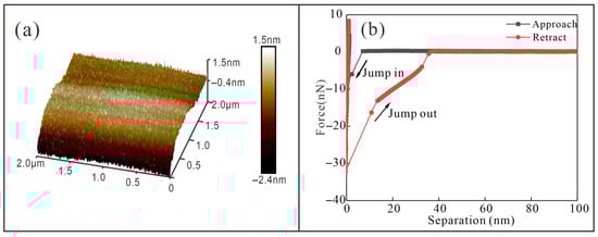
Figure 4. (a) Pore surface of mica scanning by AFM; (b) The adhesion force curves of shale oil on mica surface detect by AFM (modified from Bai et al. [46]).
3.2. Fluid Injection Technology
The fluid injection technique quantitatively characterizes pore structure by injecting fluids that do not react with the minerals of the samples. By precisely recording the amount of injected fluid during the fluid intrusion and extrusion processes, the pore structure parameters can be estimated based on the hypothetical models. This experiment is easy to perform on various porous media, whether regular or irregular. Thus, it is one of the most widely-used techniques in characterizing the pore structure of materials. According to the injected fluids, this kind of technique mainly includes mercury intrusion porosimetry (MIP), nitrogen adsorption, carbon dioxide adsorption, helium injection, etc.
The MIP technique records the injection pressure values and the volume of mercury intrusion. Based on this information, pore structure parameters, such as pore size distribution and pore volume, can be estimated according to the Washburn theory. Mercury intrusion porosimetry can be further divided into high-pressure mercury injection and constant-speed mercury injection. The differences between these two methods are the mercury injection rate and the maximum mercury injection pressure. The constant-rate mercury intrusion technique is usually conducted at a low injection rate (less than 5 × 10⁻⁵ mL/min) and limited injection pressure (maximum pressure is 900 psi) to finely characterize the pore throat information. The maximum pressure of high-pressure mercury injection is fairly higher than that of constant-speed mercury injection. The smallest pore diameter that can be detected using a maximum injection pressure of 60,000 psi is about 3–4 nm. The high-pressure mercury injection is usually applied for characterizing the wide pore size distribution of shales. However, the high-pressure mercury may compress the pores of soft minerals (clays and organic matter in shales) and even create artificial fractures at high-injection pressure conditions. Thus, the pore structure information of shales detected by MIP should be cautiously examined with the aid of other information.
Nitrogen adsorption is especially used for the investigation of nano-scaled pores [48]. Particle or powder samples are vacuumized before the experiment. Then, high-purity nitrogen is used as an adsorbent to adsorb on the pore surface of samples under different relative pressures at −196 °C. Nitrogen adsorption and desorption curves are plotted with the relative pressure as abscissa and adsorption amount as ordinate. The pore size distribution and specific surface area can be interpreted according to the physical adsorption theory [48]. The hysteresis loops, formed by the divergence between the adsorption and desorption branches, are associated with specific pore shapes. The IUPAC (International Union of Pure and Applied Chemistry) divided hysteresis loops into four types [48], as follows. The type H1 hysteresis loop is related to the cylindrical pores with openings at both ends. The type H2 hysteresis loop is always observed in the inkbottle-shaped pores with a thin neck and wide body. The type H3 hysteresis loop is associated with slit-shaped pores or fractures, while the type H4 hysteresis loop is usually related to narrow slit-shaped pores. Previous investigations have shown that the organic matter-hosted pores in shales are constituted by narrow pore throats connecting to large pore bodies [49]. Thus, the wide hysteresis loops (type H2) are always observed in shales with developed organic matter-hosted pores, while the type H3 hysteresis loops are found in pores with clay minerals (plate-like particles) [49,50]. Nitrogen adsorption is widely used to characterize nanoporous materials. However, the effective diffusion coefficients of nitrogen are low (10−14–10−12 m2/s) in micropores at low temperatures [51], which restricts the access of nitrogen to inner pores. This will result in the underestimation of the total pore volume. Moreover, samples for nitrogen adsorption are always crushed into particles that might destroy the authentic pore structure.
Other fluid injection technology, such as water injection and imbibition, is used to not only characterize the pore structure but also increase oil production. Fluid imbibition experiments were conducted to characterize the connectivity of shales according to the time exponent of water imbibition [52]. Low salinity water injection can effectively enhance oil recovery of tight reservoirs by changing rock wettability and reducing interfacial tension [53]. The enhanced oil recovery factor was reported to be up to 14% in carbonate reservoirs using low-salinity water injection [53].
This entry is adapted from the peer-reviewed paper 10.3390/en15249485
This entry is offline, you can click here to edit this entry!