Your browser does not fully support modern features. Please upgrade for a smoother experience.
Please note this is an old version of this entry, which may differ significantly from the current revision.
The use of carbon fibre-reinforced polymer (CFRP) materials is increasing in many different industries, such as those operating in the aviation, marine, and automotive sectors. In these applications, composite parts are often joined with other composite or metallic parts, where adhesive bonding plays a key role.
- composite materials
- adhesively bonded joints
- carbon fibre reinforced polymers
1. Joint Geometry
The mechanical performance of a bonded joint is known to be highly dependent on joint geometry, which includes factors such as overlap length, adherend and adhesive thickness, etc. Among the most significant of these parameters are the overlap length (l), adherend thickness (T), adhesive thickness (t) and the adherend and adhesive elastic modulus and shear strength [1]. Figure 1 presents a schematic design of a single lap joint, illustrating the aforementioned parameters.
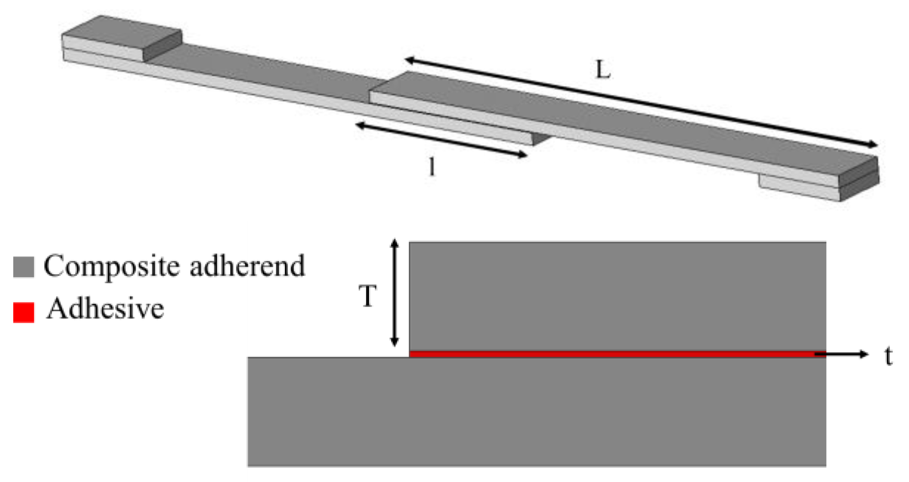
Figure 1. Schematic design of a single lap joint.
Multiple research studies have been carried out to understand the effect of the overlap length in composite joints. It can be generally stated that, if the adherend does not fail or yield, an increase in the overlap length will lead to an increase in the failure load of the joint. This is known to occur even under different loading conditions e.g., under quasi-static and impact loads (see Figure 2) [2][3][4].
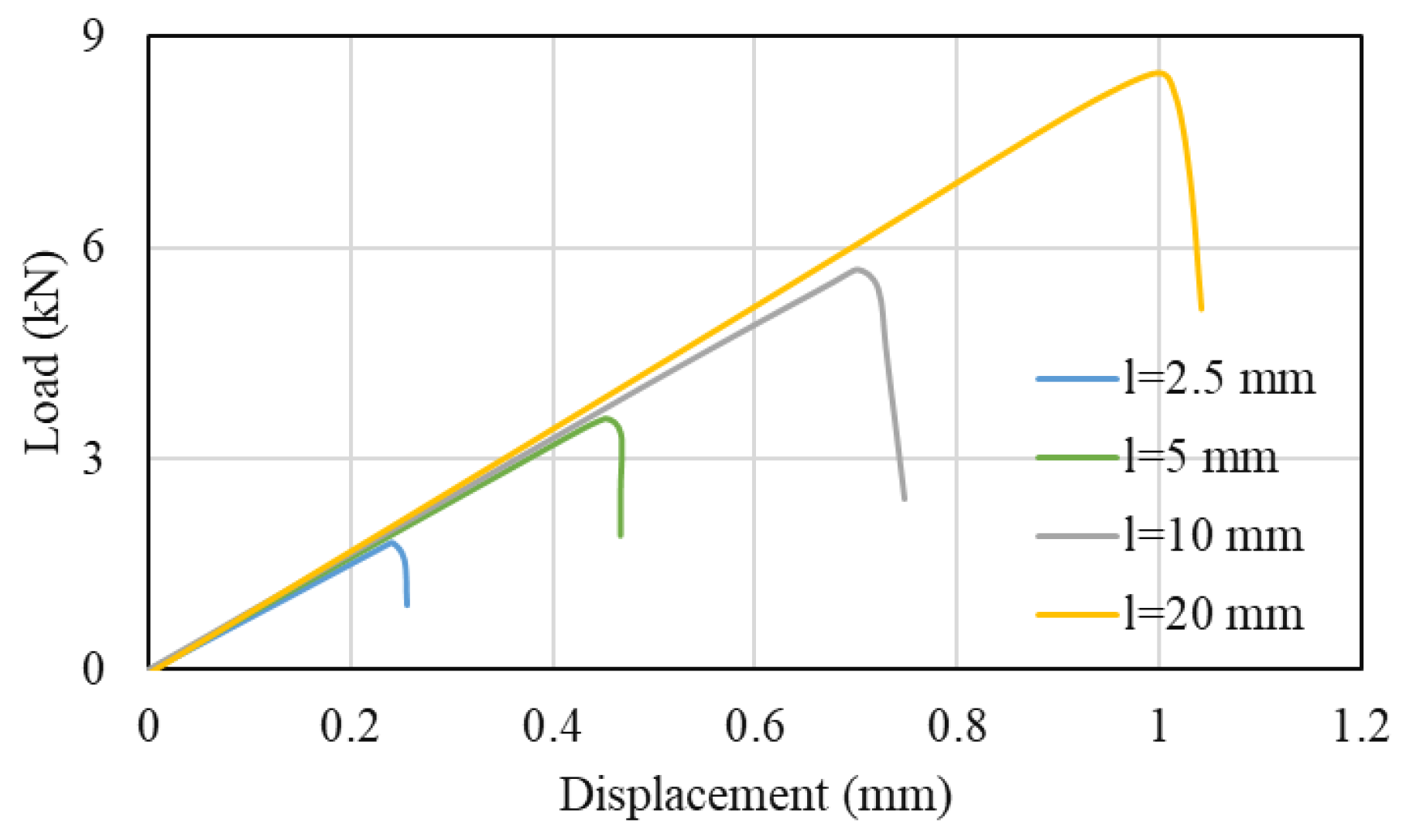
Figure 2. Load-displacement for different overlap length under tensile loading conditions. Adapted from [5].
This increase in the failure load could be explained by the substantial effect that the overlap length has on the peel stress, a fact shown numerically by Demiral and Kadioglu [6][7]. At the same time, the failure load is also highly affected by the applied strain rate in composite joints, a result of the strain rate sensitivity exhibited by the adhesive and the polymeric resin of composites [2][5].
However, if stiff and brittle adhesives are used, an increase in the overlap length will result in a more modest (or even a negligible) increase of the failure load, which is in contrast to that found for joints bonded with a ductile adhesive, where the increase in failure load is found to be almost directly proportional to the increase in overlap length. This can be explained by the fact that severe stress concentrations are generated at the overlap ends by the stiff and brittle adhesive, leading to premature failure. These stress concentrations are present even for very large overlap length values, reducing the effectiveness of increasing this dimensional parameter.
Li et al. [8] presented a thorough experimental study on the effect of adherend thickness for single lap, double lap and scarf composite joints, where a higher failure load was observed for all the mentioned configurations in larger adherend thicknesses (higher strength for single and double lap joints, but lower strength for scarf joints). In the case of scarf joints, the authors [8] showed that by increasing the scarf angle a higher lap shear strength was obtained.
2. Effect of Surface Preparation
To ensure maximum joint strength, the bonding surfaces must be thoroughly prepared before the adhesive application, which is often a costly and time-consuming process, but essential to avoid adhesive failure. Furthermore, bond strength and durability are known to be extremely sensitive to environmental parameters such as the temperature and humidity, both of which can have a deleterious effect on the adhesive/adherend interface and degrade the level of adhesion.
A proper surface treatment for composite adherends should always seek the removal of all contaminants from the surfaces and ensure a good level of adhesion, which can be achieved through an increase of wettability (increasing surface energy and the chemical activation of material surfaces being bonded) or by increasing the roughness of the surface (and increasing the level of mechanical interlocking between the adhesive and the adherend) [9][10][11]. Many different chemical and physical surface treatments are currently available for composites. These employ different methodologies, such as mechanical abrasion [12], degreasing the surface with solvent [13][14], laser ablation [15][16], plasma treatment [17][18], peel ply technique [18][19][20][21][22], irradiation [23], grit blasting [24][25] and chemical surface activation [26]. It is important to take into account the fact that the bulk mechanical properties of a composite can be strongly affected by surface treatments. For example, severe abrasive treatments can damage the composite and adversely affect joint behaviour [27][28] and bond strength [29][30]. This is because the fibres closer to the surface can be damaged by abrasion, reducing composite strength and the adhesion of the fibres to the matrix, and may even introduce contamination through loose microparticles (see Figure 3) [31]. Nonetheless, microparticles can be removed with the use of suitable high-power ultrasonic cleaning methods, and, hence, the use of primer coating together with high-power ultrasonic cleaning leads to a significant increase in strength [32].
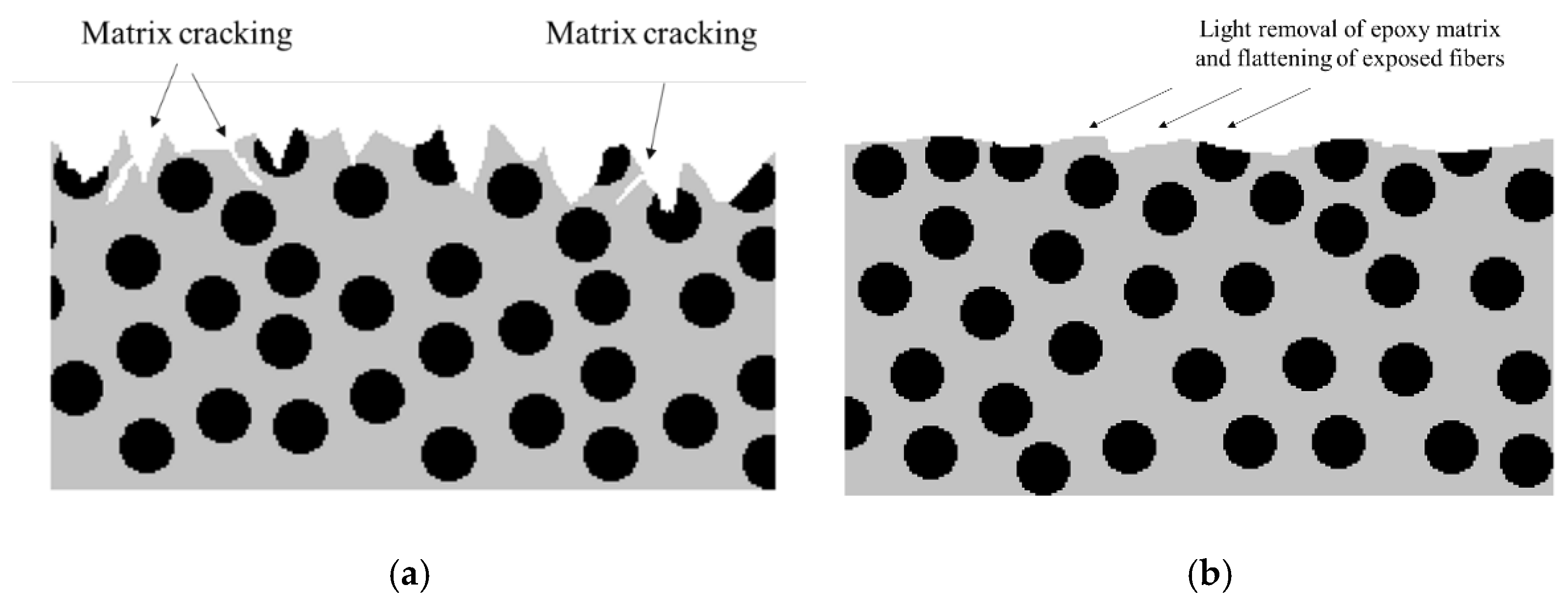
Figure 3. Schematic design of composite after (a) grit blasting and (b) sanding. Adapted from [33].
Laser surface treatment is an eco-friendly and non-contact procedure which dispenses with harmful chemical solutions and does not introduce secondary contaminations. This method can be used to provide greater roughness and wettability, leading to higher shear strength and a cohesive failure mode when compared with conventional mechanical abrasion [12][34]. It has also been shown that aging does not significantly degrade the quality of the laser-treated interface [15]. The use of this approach is well suited for the preparation of composite adherends [35], although there is still some possibility of local fibre damage with high accumulated laser fluence [36].
The use of peel ply is a commonly used technique to protect the surface of composite laminates from contamination, while also creating and maintaining a specific surface texture [20]. A peel ply layer is used to absorb any residual resin and to create an activated surface for adhesive bonding or coating by peel ply removal. This method is also able to provide a good surface treatment for bonding purposes.
Different methods are available to assess the pre-bond quality of CFRP surfaces. One of these is the optically stimulated electron emission (OSEE) [37], able to detect weak adhesive bonds of CFRP [38], which might have been caused by contamination or poor curing of the adhesive. Other methods can be used to detect defects in the laminate itself, such as the use of electromechanical impedance [39], acoustic emission [40] or ultrasonic emission [41], or the electrical resistance method [42][43][44][45]. However, interfacial defects in the form of kissing bonds may still go undetected. Attempts using advanced ultrasonic methods such as nonlinear ultrasounds, guided waves or digital image correlation (DIC) [46] inspection to detect kissing bonds have met with limited success. However, some authors report that DIC can be effective when applied in the case of partial or localized kissing bonds [46].
3. Effect of Manufacturing Process
The manufacturing process of composite joints can follow three different approaches, the selection of which can be dependent on the nature of the composite and adhesive, and their curing temperatures. These processes are known as co-curing, co-bonding and the secondary bonding method [47]. A co-bonding process is performed when one adherend is cured simultaneously with the adhesive, while in the co-curing process both adherends and the adhesive are simultaneously cured. Secondary bonding is when the adhesive layer is cured between two pre-cured composite substrates [34][47][48]. Figure 4 shows a schematic design of the mentioned manufacturing methods.
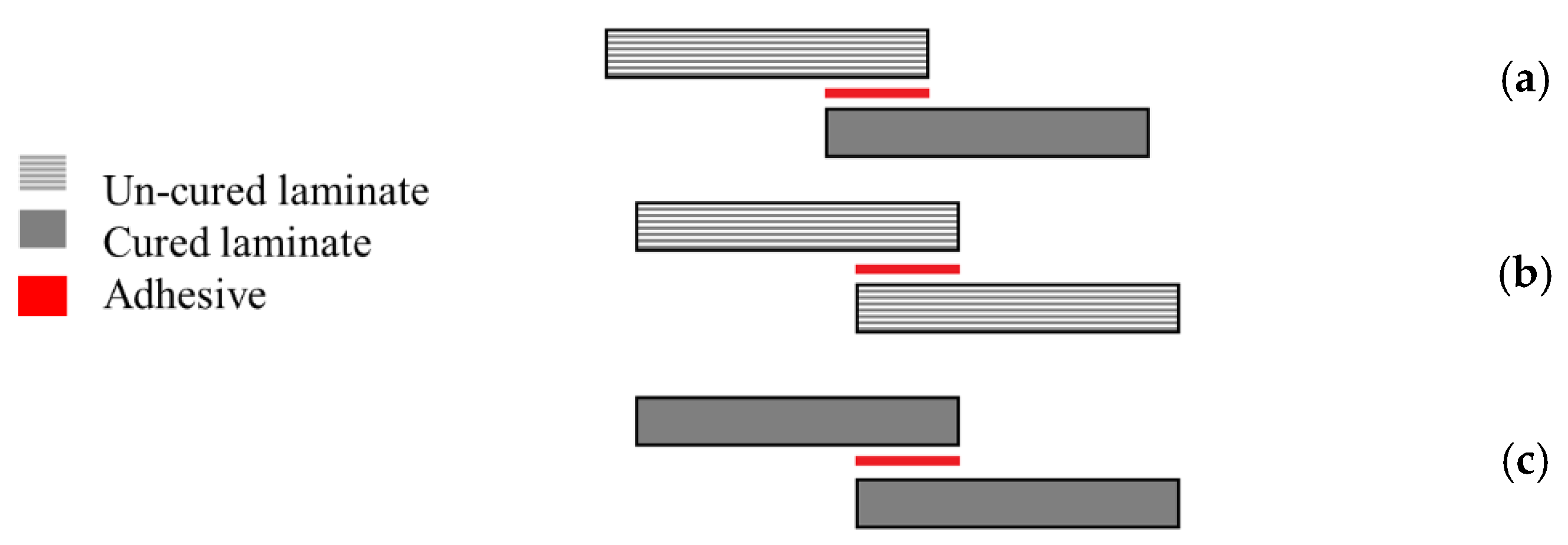
Figure 4. (a) Co-bonding, (b) co-curing, and (c) secondary bonding. Adapted from [47].
Each of these manufacturing methods is known to have its own specific advantages and disadvantages [49]. For secondary bonded joints, failure is known to occur in the composite [50] and edge effects are not so predominant [51]. On the other hand, in co-bonded joints, failure typically occurs in the adhesive, since greater resistance to crack initiation and propagation has been observed [50] and significant edge effects have been observed [51]. However, the co-bonded joints have been shown to have a lower strength than the secondary bonded joints under a wide range of loading conditions [52][53][54][55]. In some cases, the moisture present in the prepreg was found to have been released during curing and had migrated to the adhesive layer, which led to a weakening of the interface and lower strength of the co-cured joints [54][56].
Notwithstanding, co-curing or co-bonding methods are usually preferred over the secondary bonding methods, because the number of parts and curing cycles needed are reduced. Hence, secondary bonding is mostly used for the repair of composite structures while for large and complex structures the secondary bonding process is more suitable [47][57].
4. Alternative Joint Configurations
As stated above, undesired peel stresses are a main cause of delamination failure in composite adherends [58]. Accordingly, a proper joint design process should seek, as an objective, to reduce the peeling stress concentration in the overlap. Many different geometrical modifications have been proposed to reduce delamination, whether through reductions of the joint overlap length [59][60], increasing the bonded area width [61] or increasing adherend thickness [62]. As an alternative, the adherend geometry can also be changed by adding tapered sections, reducing adherend thickness [63][64], using internal tapers of adhesive [65], adding a spew fillet [66][67], using adhesively bonded joint with non-flat interfaces [68] or using wavy-lap [69] (see Figure 5a). The flat joggle flat joint (FJF) [70] (seen in Figure 5b) is a relatively complex joint design which is known to reach very high failure loads due to the compressive stress field developed [69] and its ability to overcome the bending effect [70]. However, all of these modifications require cost and time-consuming machining and manufacturing steps [66].

Figure 5. (a) Wavy-lap joint and (b) flat joggle flat joint (FJF).
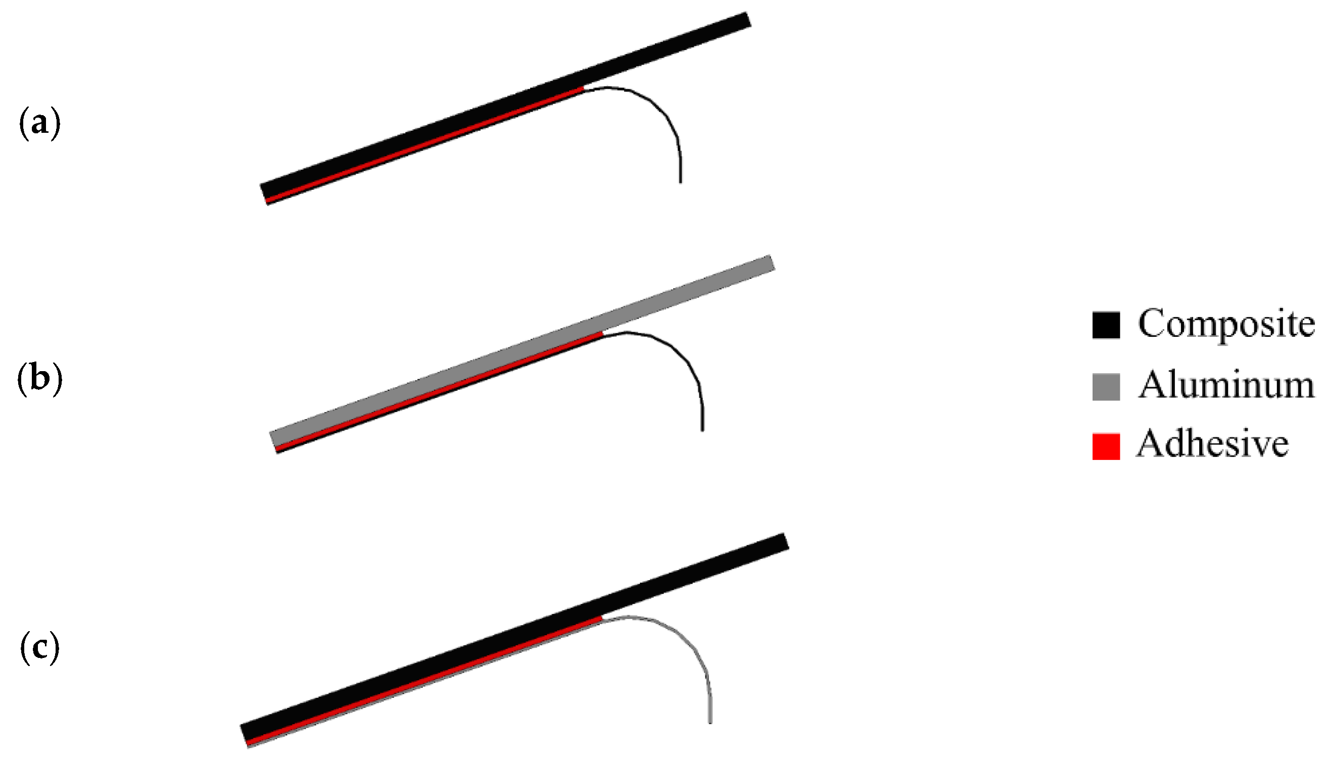
A study from Teixeira and Sinke [71] showed that peel tests could be performed in bonded composite-to-metal and composite-to-composite joints using a floated rolling peel test (see Figure 6) [71][72], and concluded that using CFRP as the flexible adherend has a considerable effect on the peel load since the peel load gives a direct indication of the failure mode [71].
This entry is adapted from the peer-reviewed paper 10.3390/ma16020568
References
- Matthews, F.L.; Kilty, F.; Godwin, E.W. A review of the strength of joints in fibre-reinforced plastics. Part 2. Adhesively bonded joints. Composites 1982, 13, 29–37.
- Araújo, H.A.M.; Machado, J.J.M.; Marques, E.A.S.; Da Silva, L.F.M. Dynamic behaviour of composite adhesive joints for the automotive industry. Compos. Struct. 2017, 171, 549–561.
- Reis, N.; Ferreira, J.A.M.; Antunes, F. Effect of adherend’s rigidity on the shear strength of single lap adhesive joints. Int. J. Adhes. Adhes. 2011, 31, 193–201.
- Ozel, A.; Yazici, B.; Akpinar, S.; Aydin, M.D.; Temiz, Ş. A study on the strength of adhesively bonded joints with different adherends. Compos. Part B Eng. 2014, 62, 167–174.
- Ye, J.; Yan, Y.; Hong, Y.; Guo, F. An integrated constitutive model for tensile failure analysis and overlap design of adhesive-bonded composite joints. Compos. Struct. 2019, 223, 110986.
- Demiral, M.; Kadioglu, F. Failure behaviour of the adhesive layer and angle ply composite adherends in single lap joints: A numerical study. Int. J. Adhes. Adhes. 2018, 87, 181–190.
- da Costa Mattos, H.S.; Monteiro, A.H.; Palazzetti, R. Failure analysis of adhesively bonded joints in composite materials. Mater. Des. 2012, 33, 242–247.
- Li, J.; Yan, Y.; Zhang, T.; Liang, Z. Experimental study of adhesively bonded CFRP joints subjected to tensile loads. Int. J. Adhes. Adhes. 2015, 57, 95–104.
- Kanerva, M.; Saarela, O. The peel ply surface treatment for adhesive bonding of composites: A review. Int. J. Adhes. Adhes. 2013, 43, 60–69.
- Islam, M.S.; Tong, L.; Falzon, J. Influence of metal surface preparation on its surface profile, contact angle, surface energy and adhesion with glass fibre prepreg. Int. J. Adhes. Adhes. 2014, 51, 32–41.
- Encinas, N.; Oakley, B.R.; Belcher, M.A.; Blohowiak, K.Y.; Dillingham, R.G.; Abenojar, J.; Martínez, M.A. Surface modification of aircraft used composites for adhesive bonding. Int. J. Adhes. Adhes. 2014, 50, 157–163.
- Li, S.; Sun, T.; Liu, C.; Yang, W.; Tang, Q. A study of laser surface treatment in bonded repair of composite aircraft structures. R. Soc. Open Sci. 2018, 5, 171272.
- Wingfield, J.R.J. Treatment of composite surfaces for adhesive bonding. Int. J. Adhes. Adhes. 1993, 13, 151–156.
- Baker, A. Bonded Repair of Aircraft Structures; Springer Science & Business Media: New York, NY, USA, 1988; Volume 7.
- Palmieri, F.L.; Belcher, M.A.; Wohl, C.J.; Blohowiak, K.Y.; Connell, J.W. Laser ablation surface preparation for adhesive bonding of carbon fiber reinforced epoxy composites. Int. J. Adhes. Adhes. 2016, 68, 95–101.
- Fischer, F.; Kreling, S.; Gäbler, F.; Delmdahl, R. Using excimer lasers to clean CFRP prior to adhesive bonding. Reinf. Plast. 2013, 57, 43–46.
- Mohan, J.; Ramamoorthy, A.; Ivanković, A.; Dowling, D.; Murphy, N. Effect of an atmospheric pressure plasma treatment on the mode I fracture toughness of a co-cured composite joint. J. Adhes. 2014, 90, 733–754.
- Holtmannspötter, J.; Czarnecki, J.V.; Feucht, F.; Wetzel, M.; Gudladt, H.J.; Hofmann, T.; Meyer, J.C.; Niedernhuber, M. On the fabrication and automation of reliable bonded composite repairs. J. Adhes. 2015, 91, 39–70.
- Arenas, J.M.; Alía, C.; Narbón, J.J.; Ocaña, R.; González, C. Considerations for the industrial application of structural adhesive joints in the aluminium–composite material bonding. Compos. Part B Eng. 2013, 44, 417–423.
- Kanerva, M.; Sarlin, E.; Hoikkanen, M.; Rämö, K.; Saarela, O.; Vuorinen, J. Interface modification of glass fibre–polyester composite–composite joints using peel plies. Int. J. Adhes. Adhes. 2015, 59, 40–52.
- Buchmann, C.; Langer, S.; Filsinger, J.; Drechsler, K. Analysis of the removal of peel ply from CFRP surfaces. Compos. Part B Eng. 2016, 89, 352–361.
- Thull, D.; Zimmer, F.; Hofmann, T.; Holtmannspoetter, J.; Koerwien, T.; Hoffmann, M. Investigation of fluorine-based release agents for structural adhesive bonding of carbon fibre reinforced plastics. Appl. Adhes. Sci. 2019, 7, 2.
- Rhee, K.Y.; Yang, J.H. A study on the peel and shear strength of aluminum/CFRP composites surface-treated by plasma and ion assisted reaction method. Compos. Sci. Technol. 2003, 63, 33–40.
- Ramaswamy, K.; O’Higgins, R.M.; Kadiyala, A.K.; McCarthy, M.A.; McCarthy, C.T. Evaluation of grit-blasting as a pre-treatment for carbon-fibre thermoplastic composite to aluminium bonded joints tested at static and dynamic loading rates. Compos. Part B Eng. 2020, 185, 107765.
- Prolongo, S.G.; Gude, M.R.; Del Rosario, G.; Ureña, A. Surface pretreatments for composite joints: Study of surface profile by SEM image analysis. J. Adhes. Sci. Technol. 2010, 24, 1855–1867.
- Schmutzler, H.; Popp, J.; Büchter, E.; Wittich, H.; Schulte, K.; Fiedler, B. Improvement of bonding strength of scarf-bonded carbon fibre/epoxy laminates by Nd: YAG laser surface activation. Compos. Part A Appl. Sci. Manuf. 2014, 67, 123–130.
- De Barros, S.; Kenedi, P.P.; Ferreira, S.M.; Budhe, S.; Bernardino, A.J.; Souza, L.F.G. Influence of mechanical surface treatment on fatigue life of bonded joints. J. Adhes. 2017, 93, 599–612.
- Brack, N.; Rider, A.N. The influence of mechanical and chemical treatments on the environmental resistance of epoxy adhesive bonds to titanium. Int. J. Adhes. Adhes. 2014, 48, 20–27.
- Baker, A.A.; Chester, R.J. Minimum surface treatments for adhesively bonded repairs. Int. J. Adhes. Adhes. 1992, 12, 73–78.
- Schubbe, J.J.; Mall, S. Investigation of a cracked thick aluminum panel repaired with a bonded composite patch. Eng. Fract. Mech. 1999, 63, 305–323.
- Oliveira, V.; Sharma, S.P.; De Moura, M.F.S.F.; Moreira, R.D.F.; Vilar, R. Surface treatment of CFRP composites using femtosecond laser radiation. Opt. Lasers Eng. 2017, 94, 37–43.
- De Freese, J.; Holtmannspötter, J.; Raschendorfer, S.; Hofmann, T. End milling of Carbon Fiber Reinforced Plastics as surface pretreatment for adhesive bonding—Effect of intralaminar damages and particle residues. J. Adhes. 2018, 96, 1122–1140.
- Morano, C.; Tao, R.; Alfano, M.; Lubineau, G. Effect of Mechanical Pretreatments on Damage Mechanisms and Fracture Toughness in CFRP/Epoxy Joints. Materials 2021, 14, 1512.
- Leone, C.; Genna, S. Effects of surface laser treatment on direct co-bonding strength of CFRP laminates. Compos. Struct. 2018, 194, 240–251.
- Akman, E.; Erdoğan, Y.; Bora, M.Ö.; Çoban, O.; Oztoprak, B.G.; Demir, A. Investigation of the differences between photochemical and photothermal laser ablation on the shear strength of CFRP/CFRP adhesive joints. Int. J. Adhes. Adhes. 2020, 98, 102548.
- Akman, E.; Erdoğan, Y.; Bora, M.Ö.; Çoban, O.; Oztoprak, B.G.; Demir, A. Investigation of accumulated laser fluence and bondline thickness effects on adhesive joint performance of CFRP composites. Int. J. Adhes. Adhes. 2019, 89, 109–116.
- Brune, K.; Lima, L.; Noeske, M.; Thiel, K.; Tornow, C.; Dieckhoff, S.; Hoffmann, M.; Stübing, D. Pre-bond quality assurance of CFRP surfaces using optically stimulated electron emission. In Proceedings of the 3rd International Conference of Engineering Against Failure, ICEAF, Kos, Greece, 26–28 June 2013; pp. 300–307.
- Kumar, R.L.; Bhat, M.R.; Murthy, C.R.L. Non Destructive Evaluation of Degradation in Bond Line of Glass Fiber Reinforced Polymer Composite Adhesive Lap Joints. Int. J. Aerosp. Innov. 2013, 5, 61–72.
- Malinowski, P.; Wandowski, T.; Ostachowicz, W. The use of electromechanical impedance conductance signatures for detection of weak adhesive bonds of carbon fibre–reinforced polymer. Struct. Health Monit. 2015, 14, 332–344.
- Teixeira de Freitas, S.; Zarouchas, D.; Poulis, J.A. The use of acoustic emission and composite peel tests to detect weak adhesion in composite structures. J. Adhes. 2018, 94, 743–766.
- Yılmaz, B.; Jasiūnienė, E. Advanced ultrasonic NDT for weak bond detection in composite-adhesive bonded structures. Int. J. Adhes. Adhes. 2020, 102, 102675.
- Kim, C.H.; Choi, J.H.; Kweon, J.H. Defect detection in adhesive joints using the impedance method. Compos. Struct. 2015, 120, 183–188.
- Baek, S.J.; Kim, M.S.; An, W.J.; Choi, J.H. Defect detection of composite adhesive joints using electrical resistance method. Compos. Struct. 2019, 220, 179–184.
- Kwon, D.J.; Wang, Z.J.; Choi, J.Y.; Shin, S.; DeVries, K.L.; Park, J.M. Damage sensing and fracture detection of CNT paste using electrical resistance measurements. Compos. Part B Eng. 2016, 90, 386–391.
- An, W.J.; Kim, C.H.; Kim, T.H.; Choi, J.H. Study on strength and defect detection capability of bonded joints according to CNT content. Compos. Struct. 2019, 207, 204–212.
- Kumar, R.V.; Bhat, M.R.; Murthy, C.R.L. Evaluation of kissing bond in composite adhesive lap joints using digital image correlation: Preliminary studies. Int. J. Adhes. Adhes. 2013, 42, 60–68.
- Budhe, S.; Banea, M.D.; De Barros, S.; Da Silva, L.F.M. An updated review of adhesively bonded joints in composite materials. Int. J. Adhes. Adhes. 2017, 72, 30–42.
- Ashcroft, I.A.; Hughes, D.J.; Shaw, S.J. Adhesive bonding of fibre reinforced polymer composite materials. Assem. Autom. 2000, 20, 150–161.
- Masmanidis, I.T.; Philippidis, T.P. Progressive damage modeling of adhesively bonded lap joints. Int. J. Adhes. Adhes. 2015, 59, 53–61.
- Bishop, S.M.; Gilmore, R.B. Fatigue of Bonded CFRP Joints: Fracture Mechanisms and Environmental Effects, Adhesion 90; Plastics and Rubber Institute: Cambridge, UK, 1990.
- Kang, S.G.; Kim, M.G.; Kim, C.G. Evaluation of cryogenic performance of adhesives using composite–aluminum double-lap joints. Compos. Struct. 2007, 78, 440–446.
- Mohan, J.; Ivanković, A.; Murphy, N. Mixed-mode fracture toughness of co-cured and secondary bonded composite joints. Eng. Fract. Mech. 2015, 134, 148–167.
- Song, M.G.; Kweon, J.H.; Choi, J.H.; Byun, J.H.; Song, M.H.; Shin, S.J.; Lee, T.J. Effect of manufacturing methods on the shear strength of composite single-lap bonded joints. Compos. Struct. 2010, 92, 2194–2202.
- Mohan, J.; Ivanković, A.; Murphy, N. Mode I fracture toughness of co-cured and secondary bonded composite joints. Int. J. Adhes. Adhes. 2014, 51, 13–22.
- Sebastiani, G.; Pfeifer, S.; Röber, L.; Katoh, J.; Yamaguchi, Z.; Takada, S. Bonding Strength of FRP-Metal Hybrids. Technol. Lightweight Struct. 2019, 3, 1–8.
- Mohan, J.; Ivanković, A.; Murphy, N. Effect of prepreg storage humidity on the mixed-mode fracture toughness of a co-cured composite joint. Compos. Part A Appl. Sci. Manuf. 2013, 45, 23–34.
- Balzani, C.; Wagner, W.; Wilckens, D.; Degenhardt, R.; Büsing, S.; Reimerdes, H.G. Adhesive joints in composite laminates—A combined numerical/experimental estimate of critical energy release rates. Int. J. Adhes. Adhes. 2012, 32, 23–38.
- Hart-Smith, L.J. Designing to minimize peel stresses in adhesive-bonded joints. In Delamination and Debonding of Materials; ASTM International: West Conshohocken, PA, USA, 1985.
- Neto, J.A.B.P.; Campilho, R.D.; Da Silva, L.F.M. Parametric study of adhesive joints with composites. Int. J. Adhes. Adhes. 2012, 37, 96–101.
- Reis, N.B.; Antunes, F.J.V.; Ferreira, J.A.M. Influence of superposition length on mechanical resistance of single-lap adhesive joints. Compos. Struct. 2005, 67, 125–133.
- Choi, J.I.; Hasheminia, S.M.; Chun, H.J.; Park, J.C. Experimental study on failure mechanism of hybrid composite joints with different adhesives. Fibers Polym. 2017, 18, 569–574.
- Seong, M.S.; Kim, T.H.; Nguyen, K.H.; Kweon, J.H.; Choi, J.H. A parametric study on the failure of bonded single-lap joints of carbon composite and aluminum. Compos. Struct. 2008, 86, 135–145.
- Da Silva, L.F.; Adams, R.D. Techniques to reduce the peel stresses in adhesive joints with composites. Int. J. Adhes. Adhes. 2007, 27, 227–235.
- Kaye, R.H.; Heller, M. Through-thickness shape optimisation of bonded repairs and lap-joints. Int. J. Adhes. Adhes. 2002, 22, 7–21.
- Lang, T.P.; Mallick, K. The effect of recessing on the stresses in adhesively bonded single-lap joints. Int. J. Adhes. Adhes. 1999, 19, 257–271.
- Tsai, M.Y.; Morton, J. The effect of a spew fillet on adhesive stress distributions in laminated composite single-lap joints. Compos. Struct. 1995, 32, 123–131.
- Rispler, A.R.; Tong, L.; Steven, G.P.; Wisnom, M.R. Shape optimisation of adhesive fillets. Int. J. Adhes. Adhes. 2000, 20, 221–231.
- Chen, I.; Wang, K.Y.; Huang, H.H. Strength and failure modes of adhesively bonded composite joints with easily fabricated nonflat interfaces. Compos. Struct. 2019, 225, 111162.
- Zeng, Q.G.; Sun, C.T. Novel design of a bonded lap joint. AIAA J. 2001, 39, 1991–1996.
- Kishore, A.N.; Prasad, N.S. An experimental study of Flat-Joggle-Flat bonded joints in composite laminates. Int. J. Adhes. Adhes. 2012, 35, 55–58.
- de Freitas, S.T.; Sinke, J. Adhesion properties of bonded composite-to-aluminium joints using peel tests. J. Adhes. 2014, 90, 511–525.
- de Freitas, S.T.; Banea, M.D.; Budhe, S.; De Barros, S. Interface adhesion assessment of composite-to-metal bonded joints under salt spray conditions using peel tests. Compos. Struct. 2017, 164, 68–75.
This entry is offline, you can click here to edit this entry!
