Your browser does not fully support modern features. Please upgrade for a smoother experience.
Please note this is an old version of this entry, which may differ significantly from the current revision.
The penetration characteristics of the slurry and the support pressure transfer mechanisms are critical to the tunnel face stability control during a mechanized excavation.
- slurry penetration
- filter cake
- tunnel face stability
1. Introduction
During the excavation process of a mechanized tunnel, the instantaneous stability of the tunnel face is provided by the bentonite slurry or by compressed air in the cutting shield chamber. This phenomenon is more obvious when using a slurry shield. Two fundamental conditions are necessary to satisfy stabilizing the tunnel face: a sufficient face support pressure in the excavation chamber and an efficient pressure transfer of the excess slurry pressure onto the soil skeleton. A large amount of research was carried out on the limit support tunnel face pressure. The first research was the silo wedge model [1] based on the limit equilibrium theory. It has been widely used due to its simplicity. Then, this model was continuously improved to be able to consider more complicated situations [2][3]. Meanwhile, the limit analysis theory [4][5][6][7] has permitted giving a reasonable range of the upper and lower bounds of the limit support pressure in a more rigorous background. This method considers a kinematically admissible velocity field (upper bound) or a statically admissible stress field (lower bound). With the continuous development of the computer performance, the construction of complex velocity fields closer to real ones has permitted improving the accuracy of the tunnel support pressure to a greater extent [8][9]. Considering numerical approaches, it is nowadays the most popular method due to the development of powerful numerical tools allowing for 3D analysis [10][11][12]. Nevertheless, numerical approaches are more computationally expensive than the limit equilibrium or limit analysis ones.
During a tunnel excavation using a slurry shield, the tunnel face is supported by the slurry which is a mixture of bentonite in suspension. The suspension slurry will create a quasi-impervious membrane (filter cake); therefore, the support pressure can be applied to resist the soil pressure and hold the groundwater pore pressure if the soil permeability is relatively low (<1 × 10⁻⁴ m/s) and the percentage of bentonite is enough [13]. However, when the soil has high permeability (>1 × 10⁻⁴ m/s) such as coarse sands and gravels or the parameters (e.g., grading, concentration, etc.) of the slurry are variable, the pressure generated in the excavation chamber may not always be effectively transferred into an effective support pressure acting on the soil skeleton. The slurry support technology in a slurry shield originated from the diaphragm wall technology [14]. Therefore, the slurry support mechanism on the excavation face has received extensive attention in past research [15][16][17][18]. The first attempts to analyze the interaction between slurry and soil were conducted by Morgenstern and Amir-Tahmasseb [14] for the purposes of open trench stabilization. However, the researchers did not establish any connection between the support mechanism and the support effect. Their theory expects that all the excess slurry pressure is transferred to the soil skeleton. Müller-Kirchenbauer [15] found that the slurry penetration behavior is determined by the soil’s grain size distribution and the slurry pressure gradient along the entire infiltration path (stagnation gradient). Based on their results, two forms of slurry and soil interaction were proposed: type I is a filter cake on the excavation surface, and type II is an infiltrated zone through the soil pores without filter cake. For type II, they stated that the slurry penetration distance was determined by the stagnation gradient and the excess pressure of the slurry. Based on this research, Kilchert and Karstedt [16] further divided the form of slurry and soil interaction into three types. In addition to the two types mentioned above, there are also combinations of the former two types, which have permitted completing the classic theoretical framework of slurry and soil interaction.
In existing theoretical research, the study of slurry and soil interaction is almost based on the porous media seepage theory, and there is no detailed analysis of the interaction form of slurry particles and soil particles at the mesoscale. Therefore, the blocking effect of porous media on fluid flow is described by a single variable, the permeability coefficient, which is usually obtained through laboratory tests [19][20]. The slurry stagnation gradient is a key indicator for evaluating the penetration behavior using laboratory tests. The dependency of the stagnation gradient on the characteristic grain size (d10) and the slurry yield point was derived from experiments [21]. The impact of key slurry parameters (e.g., bentonite concentration, clay content, viscosity, and density) on the filter cake quality was also the focus of researchers at the same time [22][23][24][25][26]. Min et al. [27] suggested a methodology to predict which of the three types (filter cake, infiltration zone, and mix between filter cake and infiltrated zone) occurs in highly permeable sands. The comparison between the average soil pore sizes (Dp) with the soil particles size suspended in slurry is the main parameter of this methodology. In laboratory sand column tests [27], the pore water pressure changes during the slurry infiltration process, and the slurry accumulation can be clearly observed at the sand column surface. However, the mesoscopic transport patterns of the slurry particles inside the sand column and the mechanism of interaction with soil particles could not be observed.
It is worth noting that for a tunnel excavation using a slurry shield, no matter what type of pressure transfer mechanism is formed at the excavation surface, the continuous rotation of the shield cutter induces cyclic mechanisms due to the cycles of excavation/support pressure. Slurry infiltration is not an instantaneous process but an ongoing one. The residual slurry particles in the ground after the cutting tools’ passage will influence the subsequent slurry infiltration behavior. The slurry penetration behavior will then be different for different penetration stages. This will influence the slurry support effect. Therefore, it is necessary to consider the time effect of the pressure transfer mechanisms. Although Krause [28] emphasized the significance of considering the time effect in the pressure transfer mechanism analysis, no in-depth research has been carried out on the slurry infiltration process. Anagnostou and Kovári [29] developed a theoretical model determining the time-dependent slurry penetration depth specifically for slurry shield tunneling. Xu et al. [30] proposed a calculation method for the pore water pressure distribution at the tunnel face based on on-site monitoring data. In all the cases, the model tests or on-site monitoring cannot effectively reflect the microscopic migration of the slurry particles in the soil pores during the different mechanism formation stages. Theoretical analysis [16][29] ignored the development of the slurry penetration and used a constant permeability coefficient. However, numerical methods can effectively reflect the mechanical characteristics of the infiltration zone at different times of the slurry infiltration process, especially the discrete element method which can intuitively reflect the microscopic mechanism of the slurry soil interaction. Zhang et al. [31] studied the formation process of the type I mechanism and the slurry key parameters’ influence on the quality of the filter cake using a CFD-DEM coupling method. However, there is no in-depth analysis of the other types of pressure transfer mechanism that can exist in real projects. The effect of the pressure transfer is not easy to evaluate when the second or third type of pressure transfer mechanism are developed. It is significant to explore the mechanism and effect of slurry support for the stability control of a slurry shield tunnel face when an intact filter cake cannot be formed.
2. Adopted Numerical Model
2.1. Modeling the Slurry Penetration Using CFD-DEM
The most common slurry penetration test is the infiltration sand column test [22][24][27][32] and a common test apparatus is shown in Figure 1. Existing numerical models [31][33] for slurry infiltration are often set up based on indoor test setups so that they can verify the validity by comparing with indoor test results. To study the slurry particles movements in the soil pores, it is necessary to use a numerical model to simulate the infiltration behavior of slurry particles. Generally, there are two ways to characterize the slurry penetration behavior in CFD–DEM calculations: (1) The use of a non-Newtonian fluid model, such as the Bingham model or Herschel–Bulkley models, which usually regard the solid particles and fluid as a unified material. (2) Independently introduce the slurry particles [34] and use a Newtonian fluid model to characterize the viscous contact between fluid and particles [35]. The effect of the slurry support pressure transfer mechanism under different types of slurry–soil interaction mechanisms is studied. The process of filling the soil pore structure with slurry particles driven by pressure gradients. Therefore, a Newtonian fluid is used and the solid phase portion of the slurry was simulated using particles independent of the carrier fluid.
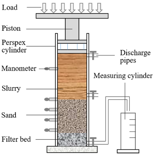
Figure 1. Schematic diagram of an infiltration column test.
2.2. CFD Numerical Model and Boundary Conditions
The CFD fluid elements are defined independently from the particles during the numerical simulation process, and the fluid elements will not move or deform with the particle’s movement. In order to ensure the calculation accuracy when using the coarse-grid method, it should contain more than five fluid elements in either direction of the model. The fluid element length should be 3 times greater than the particle size. To simulate the slurry infiltration behavior under specific support pressures at the excavation face, a stable pressure boundary (P) is set at the upper end of the model and a free drainage boundary is set at the bottom end of the model. The lateral boundary of the model is an impermeable boundary, so no radial seepage can occur. Figure 2 shows the fluid elements model with particles inside. The lower part of the model is filled with sand particles and the upper part of the model is filled with slurry particles.
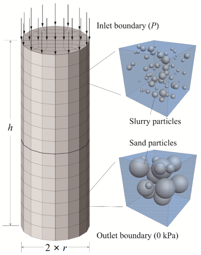
Figure 2. Schematic diagram of fluid elements with particles inside.
Different computational cases are simulated using different model sizes because of the different particle sizes, considering the time computation cost, and to avoid size and boundary effects. A numerical study was carried out to define the model sizes for each considered case.
2.3. Sand Column Initialization
In the first step to model the sand column, spherical particles were randomly generated according to the soil physical and mechanical parameters. The soil particle parameters used in the numerical calculations are shown in Table 1 [31]. The height of the sand column is defined to be equal to half of the entire computational model (Figure 2), and the model is constructed to meet the size effect requirements described above. An equilibrium under gravity is then performed. Once the sand particles have been generated and a stable state is reached, the fluid elements are set up and the seepage field is turned on to saturate the sand column at the model bottom. In the upper part of the sand column, slurry particles are generated, and a fixed pressure is applied, which allows the slurry particles to migrate due to the combined effects of the gravity and the fluid action on particles. The slurry physical and mechanical parameters are shown in Table 2 [31].
Table 1. Soil particle parameters.
| Parameters | Value |
|---|---|
| Volumetric weight | 2000 kg/m3 |
| Young’s modulus | 70 GPa |
| Poisson’s ratio | 0.3 |
| Friction coefficient | 0.5 |
| Restitution | 0.3 |
| Particle number | 5689~5877 |
| Diameter | 250~2000 μm |
| Contact model | Hertz |
Table 2. Slurry parameters.
| Items | Parameters | Value |
|---|---|---|
| Slurry particle | Volumetric weight | 2000 kg/m3 |
| Young’s modulus | 5 MPa | |
| Poisson’s ratio | 0.3 | |
| Friction coefficient | 0.05 | |
| Restitution | 0.3 | |
| Particle number | 28,461~371,083 | |
| Diameter | 20~160 μm | |
| Contact model | Hertz | |
| Fluid | Volumic weight | 1000 kg/m3 |
| Kinematic viscosity | 1 × 10⁻⁶ m2/s | |
| Fluid type | Newtonian |
This entry is adapted from the peer-reviewed paper 10.3390/buildings12101744
References
- Horn, M. Horizontal earth pressure on perpendicular tunnel face. In Hungarian National Conference of the Foundation Engineer Industry; Hungary Press: Budapest, Hungary, 1961; pp. 7–16.
- Anagnostou, S.T.G. The contribution of horizontal arching to tunnel face stability. Geotechnik 2012, 35, 34–44.
- Anagnostou, G.; Perazzelli, P. The stability of a tunnel face with a free span and a non-uniform support. Geotechnik 2013, 36, 40–50.
- Leca, E.; Dormieux, L. Upper and lower bound solutions for the face stability of shallow circular tunnels in frictional material. Géotechnique 1990, 40, 581–606.
- Soubra, A.H. Kinematical approach to the face stability analysis of shallow circular tunnels. In Proceedings of the 8th International Symposium on Plasticity, Vancouver, BC, Canada, 2000; pp. 443–445. Available online: https://hal.archives-ouvertes.fr/hal-01008370 (accessed on 14 September 2022).
- Subrin, D.; Wong, H. Stabilité du front d’un tunnel en milieu frottant: Un nouveau mécanisme de rupture 3D. CR Mécanique. 2002, 330, 513–519.
- Ding, W.; Liu, K.; Shi, P.; Li, M.; Hou, M. Face stability analysis of shallow circular tunnels driven by a pressurized shield in purely cohesive soils under undrained conditions. Comput. Geotech. 2018, 107, 110–127.
- Mollon, G.; Dias, D.; Soubra, A.-H. Face Stability Analysis of Circular Tunnels Driven by a Pressurized Shield. J. Geotech. Geoenviron. 2010, 136, 215–229.
- Mollon, G.; Dias, D.; Soubra, A.-H. Rotational failure mechanisms for the face stability analysis of tunnels driven by a pressurized shield. Int. J. Numer. Anal. Methods Géoméch. 2010, 35, 1363–1388.
- Huang, M.; Li, S.; Yu, J.; Tan, J.Q.W. Continuous field based upper bound analysis for three-dimensional tunnel face stability in undrained clay. Comput. Geotech. 2018, 94, 207–213.
- Zou, J.; Chen, G.; Qian, Z. Tunnel face stability in cohesion-frictional soils considering the soil arching effect by improved failure models. Comput. Geotech. 2018, 106, 1–17.
- Zhang, C.; Li, W.; Zhu, W.; Tan, Z. Face stability analysis of a shallow horseshoe-shaped shield tunnel in clay with a linearly increasing shear strength with depth. Tunn. Undergr. Space Technol. 2020, 97, 103291.
- Zhang, Y.; Gong, G.; Yang, H.; Li, W.; Liu, J. Precision versus intelligence: Autonomous supporting pressure balance control for slurry shield tunnel boring machines. Autom. Constr. 2020, 114, 103173.
- Morgenstern, N.; Amir-Tahmasseb, I. The Stability of a Slurry Trench in Cohesionless Soils. Géotechnique 1965, 15, 387–395.
- Müller-Kirchenbauer, H. Stability of slurry trenches. In Proceedings of the 5th European Conference on Soil Mechanics and Foundation Engineering, Madrid, Spain, 10–13 April 1972; pp. 543–553.
- Kilchert, M.; Karstedt, J. Band 2 Standsicherheitsberechnung von Schlitzwaenden nach DIN 4126; Bauverlag GmbH (Beuth-Kommentare): Wiesbaden/Berlin, Germany, 1984.
- Zizka, Z.; Schoesser, B.; Thewes, M. Investigations on transient support pressure transfer at the tunnel face during slurry shield drive part 1: Case A–Tool cutting depth exceeds shallow slurry penetration depth. Tunn. Undergr. Space Technol. 2021, 118, 104168.
- Talmon, A.M.; Mastbergen, D.R.; Huisman, M. Invasion of Pressurized Clay Ssuspension into Granular Soil. J. Porous Media 2013, 351–365.
- Watanabe, T.; Yamazaki, H. Giant size slurry shield is a success in Tokyo. Tunn. Tunnell. 1981, 13, 13–17.
- Khan, R.A.; Sharma, R. Strength and Durability Characteristics of Rice Husk Ash Concrete Reinforced with Polypro-pylene Fibres. Jordan J. Civ. Eng. 2018, 12, 653–668.
- Simons, H.; Ruppert, F. Entwicklung geeigneter Verfahren zum Messen der physikalischen Eigenschaften von Ben-tonitsuspensionen auf Baustellen. In Mitteilung des Lehrstuhls für Grundbau und Bodenmechanik; Technische Universität: Braunschweig, Germany, 1982.
- Cheng, Z.L.; Wu, Z.M.; Xu, Y.Y. Experimental study on stability of excavation face of slurry shield tunnel construction in sandy ground. J. Yangtze River Sci. Res. Institute. 2001, 18, 53–55. (In Chinese)
- Fritz, P. Additives for Slurry Shields in Highly Permeable Ground. Rock Mech. Rock Eng. 2006, 40, 81–95.
- Fritz, P.; Hermanns, S.R.; Heinz, A. Modified bentonite slurries for slurry shields in highly permeable soils. In Proceedings of the 4th International Symposium Geotechnical Aspects of Underground Construction in Soft Ground, Toulouse, France, 28–31 August 2002.
- Han, X.R.; Zhu, W.; Liu, Q.W.; Zhong, X.C.; Min, F.L. Influence of slurry property on filter cake quality on working face of slurry shield. Rock Soil Mech. 2008, 29, 288–292. (In Chinese)
- Min, F.-L.; Zhu, W.; Han, X.-R.; Zhong, X.-C. The Effect of Clay Content on Filter-Cake Formation in Highly Permeable Gravel. Geotech. Spec. Publ. 2010, 204, 210–215.
- Min, F.; Zhu, W.; Han, X. Filter cake formation for slurry shield tunneling in highly permeable sand. Tunn. Undergr. Space Technol. 2013, 38, 423–430.
- Krause, T. Schildvortrieb Flüssigkeitsgestuetzte Ortsbrust. Master’s Thesis, Technische Universität, Braunschweig, Germany, 1987.
- Anagnostou, G.; Kovdri, K. The face stability of slurry-shield-driven tunnels. Tunn. Undergr. Sp. Tech. 1994, 9, 165–174.
- Xu, T.; Bezuijen, A. Analytical methods in predicting excess pore water pressure in front of slurry shield in saturated sandy ground. Tunn. Undergr. Space Technol. 2018, 73, 203–211.
- Zhang, Z.; Yin, T.; Huang, X.; Dias, D. Slurry filtration process and filter cake formation during shield tunnelling: Insight from coupled CFD-DEM simulations of slurry filtration column test. Tunn. Undergr. Space Technol. 2019, 87, 64–77.
- Zizka, Z.; Schoesser, B.; Thewes, M.; Schanz, T. Slurry Shield Tunneling: New Methodology for Simplified Prediction of Increased Pore Pressures Resulting from Slurry Infiltration at the Tunnel Face Under Cyclic Excavation Processes. Int. J. Civ. Eng. 2018, 17, 113–130.
- Rui, J.; Wei, Z.; Fan-Lu, M. Effect of Particle Size Distribution of Slurry and Pore Size of Stratum on Formation of Filter Cake in Slurry Shield. China J. Highw. Transp. 2017, 30, 100–108.
- Yang, D.; Xia, Y.M.; Wu, D.; Chen, P.; Zeng, G.Y.; Zhao, X.Q. Numerical investigation of pipeline transport character-istics of slurry shield under gravel stratum. Tunn. Undergr. Space Technol. 2018, 71, 223–230.
- Bonkinpillewar, P.D.; Kulkarni, A.; Panchagnula, M.V.; Vedantam, S. A novel coupled fluid–particle DEM for simulating dense granular slurry dynamics. Granul. Matter 2015, 17, 511–521.
This entry is offline, you can click here to edit this entry!