In the future, autonomous vehicles with full self-driving features will populate the public roads. However, fully autonomous cars will require robust perception systems to safely navigate the environment, which includes cameras, RADAR devices, and Light Detection and Ranging (LiDAR) sensors. LiDAR is currently a key sensor for the future of autonomous driving since it can read the vehicle’s vicinity and provide a real-time 3D visualization of the surroundings through a point cloud representation. These features can assist the autonomous vehicle in several tasks, such as object identification and obstacle avoidance, accurate speed and distance measurements, road navigation, and more. However, it is crucial to detect the ground plane and road limits to safely navigate the environment, which requires extracting information from the point cloud to accurately detect common road boundaries.
1. Introduction
For the last 20 years, autonomous driving has been a well-established research topic. However, despite some prototypes being already available and running, the automotive industry is only now starting to provide commercial products, which will soon turn autonomous driving vehicles mainstream. Aiming at reaching SAE-level 5, vehicles are being equipped with several ADAS features, which are constantly being improved every year. This pushes research to advance in different sensing technologies and in creating more robust perception systems.
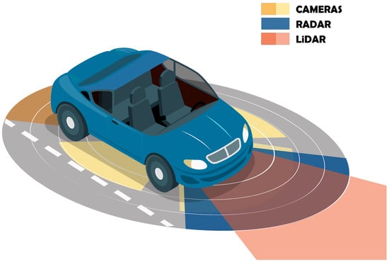
Figure 1 depicts a typical multi-sensor perception system composed of cameras, RADAR, and LiDAR sensors, which can help in providing cross-traffic alerts, blind spot assist
[1], Adaptive Cruise Control (ACC)
[2], pedestrian detection and avoidance
[3], and Automatic Emergency Braking (AEB)
[4][5]. Together, all these sensors allow retrieving redundant information about the surrounding environment, ensuring that high-level autonomous driving decisions are made based on accurate representations of the vehicle’s vicinity.
Figure 1. Multi-sensor perception system.
Among all sensors, LiDAR is becoming the most important in autonomous applications as it can provide up to 300 m of real-time 3D information about the vehicle’s surroundings. Compared with RADAR, which shares the same working principle of measuring distances based on the round-trip time of an emitted signal, LiDAR can operate in much higher frequencies due to the light properties. Moreover, while RADAR sensors only provide angular resolutions of at most 1 degree, which is insufficient for object shape estimation
[6], LiDAR sensors can achieve resolutions of tenths of degrees. Thus, their output can be used for object segmentation rather than solely object detection. Nonetheless, because LiDAR sensors use light, they still present disadvantages when compared with radio-based sensors. Since light has high absorption in water, adverse weather conditions, such as heavy rainfall, can affect the overall performance of LiDAR. On the other hand, the higher wavelengths used in RADAR can present good performance in poor weather, making this sensor capable of covering longer distances but with less emitted power.
Regarding the resolution of the output data, cameras can achieve colored and high-resolution information about the driving environment. However, they are subject to several light-related issues, e.g., they cannot corrrectly work at night or in the presence of intense light sources, which can turn the segmentation tasks relying solely on cameras quite challenging. Additionally, depth information about the environment is only possible with stereo cameras and further image processing, which affects the distance measurements.
2. LiDAR Technology
There is a plethora of LiDAR sensors currently available on the market
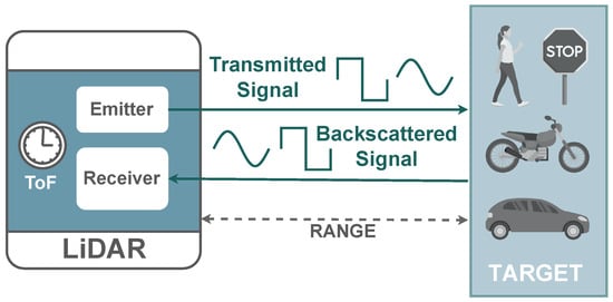
[7][8]. Despite all sharing the same light-based operation properties, manufacturers already provide different measurement and imaging systems approaches, which translates into different performance metrics and overall costs. As depicted in
Figure 2, a LiDAR sensor uses a light signal to measure distances, which are calculated based on the round-trip delay (
τ) between a signal emitted by a laser and reflected by a target. Since the speed of light (
c) is previously known, the distance (
R) to the target is calculated using Equation.
Figure 2. LiDAR working principle.
2.1. Measurement Techniques
Depending on the sensor’s technology, the round-trip delay, also known as the Time-of-Flight (ToF), can be measured through different techniques
[9][10]: pulsed, Amplitude Modulated Continuous Wave (AMCW), and Frequency Modulated Continuous Wave (FMCW). Measurement techniques based on pulsed signals are more straightforward to implement as they only require accurate timers or Time-to-Digital Converters (TDC) to directly measure and calculate the ToF. Due to their simplicity, they offer a low-cost and small-size implementation but are more subject to low Signal-Noise Ratio (SNR), which limits the accuracy of the measurements. With AMCW and FMCW, instead of sending short high-intensity pulses, the sensor emits a modulated continuous wave signal, consequently achieving better SNR values. In an AMCW system, the sensor emits a wave synchronized with a series of integrating windows. Since the reflected wave is expected to be out of phase, the distance can be calculated based on the energy ratio present on each window: short distances result in a reflected signal more present in the first windows, while for long distances, the reflected signal can be found in the last windows.
Similarly to pulsed-based sensors, AMCW can also provide a simple design. However, long-range detection requires longer wavelengths to ensure that the phase difference between signals does not exceed the signal’s period, which would produce distance ambiguity. Therefore, their application is limited mainly to mid- and short-range sensors due to eye safety regulations. On the other hand, FMCW systems modulate the emitting signal frequency with an up-chirp signal that increases its frequency over time. Then, the sensor computes the difference between the frequency of the return signal and a local oscillator, being this delta directly proportional to the distance to the target. Despite providing more robustness to external light sources and even allowing to directly retrieve the speed of a moving target due to Doppler shift, the increase in optical components makes FMCW-based sensors more expensive to build.
2.2. Imaging Techniques
To create a 3D point cloud representation in real time, LiDAR sensors emit and collect signals across multiple directions within their supported Field of View (FoV), which can result in a point cloud holding millions of points. This is achieved by using different imaging techniques
[11], such as solid-state, rotor-based, and flash-based sensors. Velodyne pioneered rotor-based LiDAR sensors. By having a mechanical system that spins the scanning part, they can create a 360º horizontal FoV, while the number of existing emitter/receptor pairs, also known as channels, define the vertical FoV. This technology was so successful that today it is the most used in LiDAR, which resulted in several manufacturers competing in this market niche. However, they still come with some limitations, such as price, bulkiness, and the reduced frame rate caused by mechanical parts.
Regarding the existing solid-state scanning solutions, some technologies, e.g., mirror MEMS
[12] and Optical Phased Array (OPA)
[13], are being deployed to replace the bulky rotational parts existing in rotor-based sensors. Despite achieving faster scanning frequencies and offering a better overall design for mass production (which reduces the overall product price), the sensor’s range is still a limitation due to power restrictions in the laser unit. Additionally, for applications requiring larger FoV, multiple sensors must be attached to the setup to guarantee the full coverage of the surrounding environment. Aiming at reducing the limitations created by complex bulky, or tiny steering systems, a flash-based LiDAR sensor does not require any steering system to emit laser signals across the FoV. Instead, it uses a flash of light to illuminate the entire environment while photo-detectors collect the back-scattered light. By simultaneously sharing the light source across all the FoV, capturing data results in a faster operation, making these sensors highly immune to light distortion
[14]. However, despite the simplicity of the emitter, the receiver system is quite complex since it must be able to differentiate the returning light from each point. In order to guarantee a suitable sensor spatial resolution, these sensors require high-density photo-detection arrays, which makes them more expensive when compared with other solid-state solutions.
3. LiDAR Applications
LiDAR is a key sensor in a perception system since its output can be used for improving autonomous driving tasks based on sensor fusion processing
[15], e.g., object detection and segmentation for object classification and collision avoidance
[16][17][18], Simultaneous Localization and Mapping (SLAM) applications
[19], the detection and navigation of the drivable area
[20][21], and much more. The LiDAR output is a point cloud, which is an exact 3D image of the environment captured by the sensor. Humans do not easily understand its information at first sight, but algorithms can do a great job of interpreting its content.
3.1. Object Detection and Classification
There are many methods and algorithms for detecting and classifying objects in point cloud data, but first, it is necessary to find them. After converting raw data into a point cloud structure, one of the first steps is the point clustering or segmentation, which basically consists in grouping points based on common characteristics
[16]. After this step, redundant data can be filtered/removed from the point cloud, resulting in less data to be transferred and processed in the upcoming phases. In applications where the sensor keeps a stationary position, some algorithms start by classifying the point cloud into background and foreground data
[17][18]. Points that share the same position across multiple frames are considered background, being discarded as they do not represent dynamic objects. For the remaining points (foreground), the distance between points is measured, and points close to each other are clustered and marked with a bounding box as they possibly represent an object. However, when the sensor moves with the car, these approaches are not effective, as the background and objects move together inside the point cloud. Therefore, automotive approaches require robust and faster algorithms since the objects in the point cloud also change at higher frequencies. First approaches applied hand-crafted features and sliding windows algorithms with Support Vector Machine (SVM) classifiers for object identification, but soon were replaced by other improved methods such as 2D representations, volumetric-based, and raw point-based data, which deploy machine learning techniques in the perception system of the vehicle
[22].
3.2. SLAM
SLAM, a well-established research topic in the field of robotics that studies solutions to build real-time localization maps based solely on perception data, has also been proposed to be applied in autonomous vehicle applications, even despite the considerable amount of 3D information the LiDAR sensor generates. Usually, odometry uses data from several sensors, e.g., IMUs and cameras, to estimate the vehicle’s position relative to a starting location. However, because LiDAR sensors can generate high data rates, some approaches follow the trend of LOAM
[19], which processes the odometry task at a higher frequency, and the mapping at a much lower rate to keep the real-time requirements. Despite providing good results, they tend to suffer from problems associated with accumulated drift. To minimize this issue, some methods apply an extra re-localization step, either using offline map information to improve the position estimation, or by combining data from other sensors. Some learning-based approaches are also emerging, which can use a pipeline of Convolutional Neuronal Networks (CNNs) to manage local feature descriptors, infer the localization offset, and apply temporal smoothness due to the sequential nature of the localization task. These require, however, more computational requirements.
3.3. Drivable Area Detection
In autonomous vehicle navigation, detecting the drivable area is one of the most critical tasks. For the car to safely move in the environment, it is necessary the detection of not only obstacles such as pedestrians or other vehicles but also several road features such as road boundaries, i.e., curbs, asphalt berms, walls and other geometric features, crosswalks, sidewalks, traffic signs, etc.
[20][21]. Since LiDAR sensors can provide intensity information in the point cloud, it becomes easier to identify high-reflection road elements such as traffic signs and road marking paint. Nonetheless, to reduce data transfer, it is also necessary to distinguish background from foreground data, including ground. By classifying point cloud data into ground and non-ground points, the drivable area can be detected more efficiently since there are less points to process, which improves the navigation features of the autonomous car while keeping the real-time requirements.
This entry is adapted from the peer-reviewed paper 10.3390/s23020601