Your browser does not fully support modern features. Please upgrade for a smoother experience.
Please note this is an old version of this entry, which may differ significantly from the current revision.
Powder injection molding (PIM) is a well-known technique to manufacture net-shaped, complicated, macro or micro parts employing a wide range of materials and alloys. Depending on the pressure applied to inject the feedstock, this process can be separated into low-pressure (LPIM) and high-pressure (HPIM) powder injection molding. Although the LPIM and HPIM processes are theoretically similar, all steps have substantial differences, particularly injection molding, which is the topic of this entry.
- feedstock
- debinding
- sintering
- binder system
1. Low Pressure Powder Injection Machine and Mold
John and Isaiah Hyatt, two brothers, received the first patent for an injection molding machine, a device that used a plunger injection technique to fill cavities, in 1872. Since this injection molding machine operates under low pressure during the injection step, it can be considered an example of Low Pressure Powder Injection Molding (LPIM) [1]. Examples of materials suitable for LPIM are ceramic or metallic compounds with fluidic characteristics and a low viscosity between 1.5 and 4.0 Pa·s. Due to their low viscosity, the transfer into the mold can occur with compressed air and a pressure of 0.8 MPa. Therefore, a complex hydraulic unit, pistons, and spindles are not essential as with the conventional High Pressure Powder Injection Molding (HPIM) machine. Other main advantages of the LPIM are low energy consumption, using simple hydraulic mechanisms, small size and lower equipment costs, lower mold wear, lower contamination of the mixture from spindle or piston wear, minimal mixture adhesion to mold, and non-separation of polymer from metallic powder. An LPIM machine is built with an electric heating tank, a mixing and stirring mechanism for preparing the binder system, a vacuuming system, and a unit for casting under pressure by applying compressed air. An LPIM machine is suitable for laboratory tests and production since, on the one hand, it has no moving parts such as screws. On the other hand, large production quantities are possible due to additional tanks for feedstock preparation [2][3][4].
New concepts for LPIM machines have been established and developed in recent years. A system design having a conical container with heaters was presented by Peltsman and Peltsman [5] 30 years ago, which was suitable enough to maintain the feedstock in the container in a molten state. Similar ideas for injection molding have been put forth by Goncalves [6]. After homogenizing and de-aerating the feedstock, the container is pressurized to allow the feedstock to flow through an interconnection pipe and an injection valve into the mold cavity. Figure 1 depicts this mechanism in illustrative form.
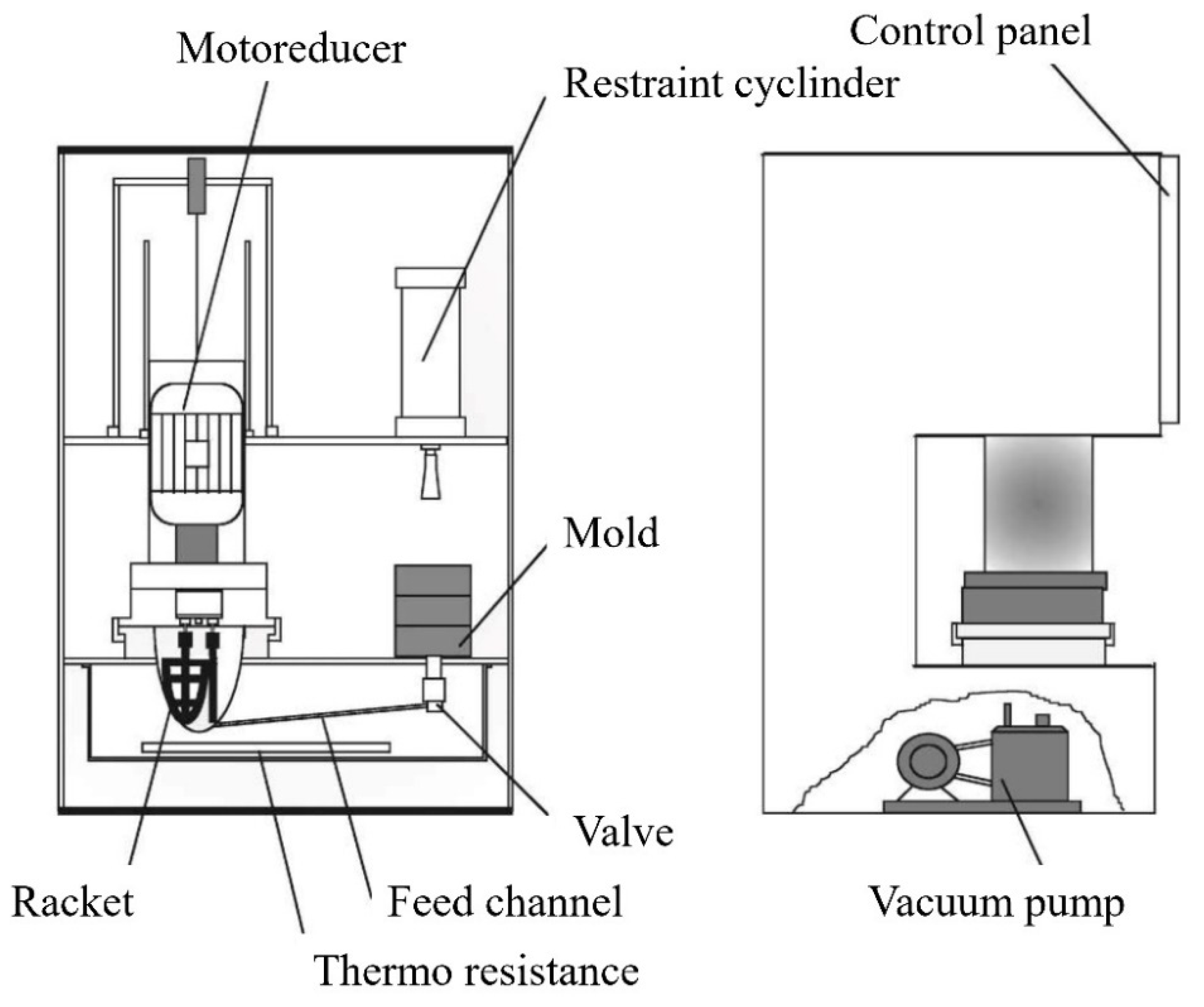
Figure 1. Schematic illustration of LPIM machine. Reproduced with permission from reference [6], copyright © 2001 Elsevier Science B.V.
The approach of Nishio and Kawashima [7] involves supplying the mold with feedstock through a pipe while transporting the feedstock without air pressure but with a pump attached to the outlet of a feedstock container. The flow of feedstock through the pump, the container’s input, and the mold’s gate can all be managed by valves. Yamada and Saito [8] proposed a concept for an LPIM machine with a proportional pump connected to the outlet of a raw material hopper and supplying the mold with a constant amount of raw material via a feed pipe and barrel to prevent air from being trapped in the raw material during the injection. Ivzhenko et al. [9] modified an injection machine using a screw pump to transport the feedstock from the hopper to the injection plunger. The mixture is injected into the mold cavity at an injection pressure of up to 20 MPa. This method is suitable for micro/nano-size PIM. Keizo et al. [10] proposed an injection molding machine combining a standard system with a second-stage pressure piston. Goceram AB Corporation [11] used a similar piston system for the medium-pressure powder injection, where the powder-binder mixture flows through a connecting tube from the container to the injection cylinder. The piston of the injection cylinder is then used to convey the starting material into the mold cavity. Lamarre et al. [12] developed an innovative concept for LPIM in which segregation and dead time can be prevented. For this purpose, the interconnecting pipe is eliminated, so strong segregation of the low-viscosity feedstock cannot occur.
Compared to HPIM, low-cost materials such as steel, aluminum, and brass can be used for molds due to their low temperatures and low pressures. According to different studies, silicone molds are also suitable for LPIM because they are reusable and cheap [13][14][15].
2. Parameters and Defects
The injection molding parameters, i.e., injection pressure and temperature, injection speed, holding time and pressure, and mold cooling, strongly influence the final properties and processing efficiency. The filling is the most critical step in the LPIM process since it is susceptible to flaws, including voids, sink marks, blasting, dead zones, warpage, welding lines, and cracks. Most problems might be prevented if the LPIM procedure were carried out under ideal processing conditions in a well-built mold, using an appropriate feedstock. The feedstock, part size and form, and mold design must all be considered when choosing the parameters [16][17][18].
Due to the higher amount of feedstock to fill the mold, the material compression and density of the green component are improved when the injection pressure is increased. In addition, the green part shrinkage is simultaneously decreased. LPIM feedstocks are typically injected at pressures between 0.7 and 20 MPa (7 and 200 bar) in many studies [12][19][20][21]. The amount of pressure that can be increased depends on the viscosity, but in practice, only an increase between 0.5–0.7 MPa is feasible. The injection speed as a parameter will not significantly affect the part quality. Although at speeds between 25 and 100 cm3/s, the compaction can be enhanced. Based on density measurements, it is evident that lower injection speeds should be used for feedstocks with higher temperatures because their viscosities have been sufficiently reduced. Due to several feedstock constituents, the processing temperature is a critical LPIM parameter. The processing temperature of 90 °C for the feedstocks, including only waxes without any backbone, reduces porosity and shrinkage. In addition, the temperature difference between mold and feedstock in complex mold geometries must also be considered. A heated mold can lead to a reduction of mechanical stresses. If the temperature difference between the feedstock and the mold is minor (slow hardening), PW migrates from the inner to the surface, forming big crystals. Therefore, the outer layers may contain more PW than the layers inside the part. If the temperature difference is large enough, rapid hardening will form tiny paraffin crystals. In this case, PW moves slowly; the injected body has a more uniform paraffin distribution and less volume change, resulting in higher density and mechanical properties [22].
Shahidi Moghadam et al. [23] investigated the fabrication of titanium parts from dehydride titanium powder using LPIM. For this purpose, three powder charges were compared in the study. In order to produce a defect-free green part, the parameters 7–10 bar and 150–165 °C were selected. The mold temperature was chosen as 60 °C, and the injection time of 8 s. The results showed only one defect-free green part with 53% powder by volume when the temperature was 165 °C. In addition, it has been observed, as shown in Figure 2, that short shots occur at higher powder loading, such as 60 vol.%, even if a high temperature of 165 °C is used. Short shots can arise when using low mold temperature and injection temperature, although too low injection pressures also could result in incomplete mold filling. Due to low flowability, solidification occurs before the entire mold is filled in a short shot.
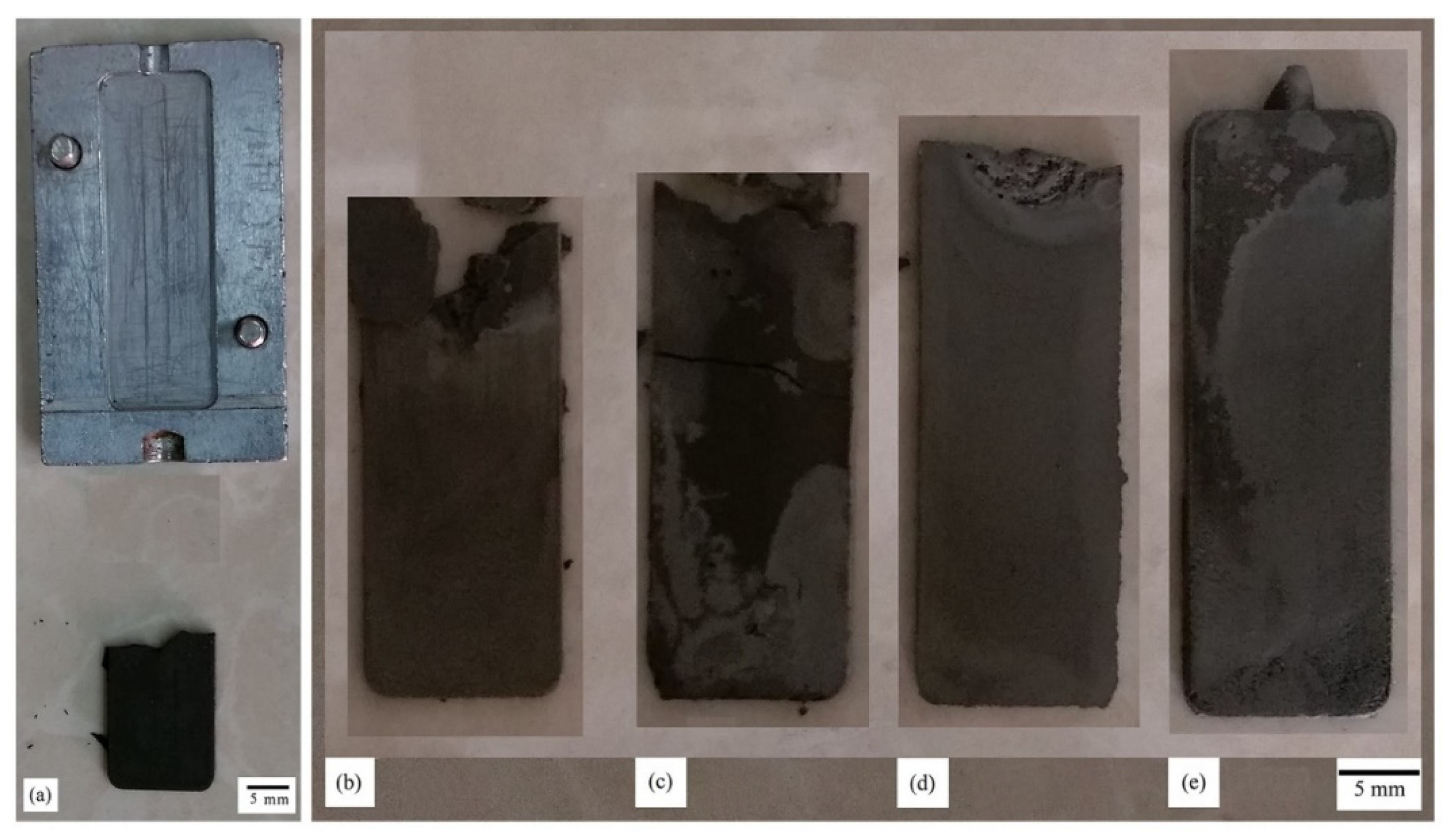
Figure 2. Injection molded parts: (a) 60 vol.% powder loading at the feedstock temperature of 165 °C; (b) 53 vol.% powder loading at the feedstock temperature of 150 °C; (c) 53 vol.% powder loading at the feedstock temperature of 155 °C; (d) 53 vol.% powder loading at feedstock temperature of 160 °C; (e) 53 vol.% powder loading at feedstock temperature of 165 °C. Reproduced with permission from reference [23], copyright © 2020, Elsevier B.V.
Fayyaz et al. [20] studied the LPIM of cemented tungsten carbide components. Due to high pressures exceeding 12 bar combined with high fill rates, jetting happened during the injection testing. The defect has been shown in Figure 3. In LPIM, jetting and flow lines, according to Piotter et al. [24], can be avoided when the pressure is lower than 10 bar. However, insufficient feedstock feeding into the mold occurs if the pressure is too low during the injection. Therefore, the individual parameters must be set precisely to produce defect-free parts. The selection of proper injection molding parameters should be considered to reduce defects and failed parts because the imperfections in the green part may introduce some problems in the debound or sintered part [25][26][27].
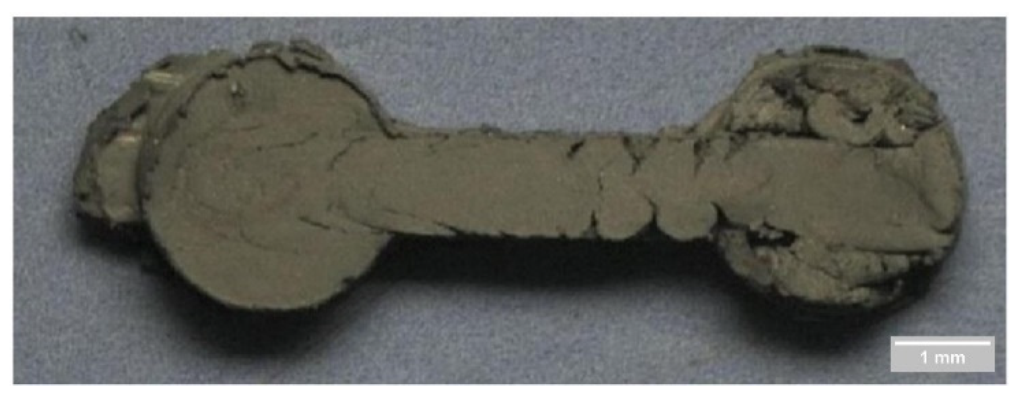
Figure 3. Jetting problem during the injection molding step. Reproduced with permission from reference [20], copyright © 2014 Elsevier B.V.
The molding parameters significantly influence the quality of the injected components. However, irregularities during feedstock preparation cannot be corrected during injection molding [28][29]. In summary, mold design and feedstock quality significantly impact the injection parameters. This leads to the conclusion that not one collection of circumstances is thought to be sufficient for the molding process. Injection times, for instance, varied from 5 to 60 s with a mold filling speed of 1.5 cm3/s [30].
The mold temperature significantly impacts the injection step and subsequently influences the following stages. According to Fayyaz et al. [20], the optimal injection parameters were 110 °C injection temperature, 10 bar pressure, 7 s injection time, and the mold temperature of 105 °C. The results showed that mold temperature significantly influences the injection molding quality (Figure 4).
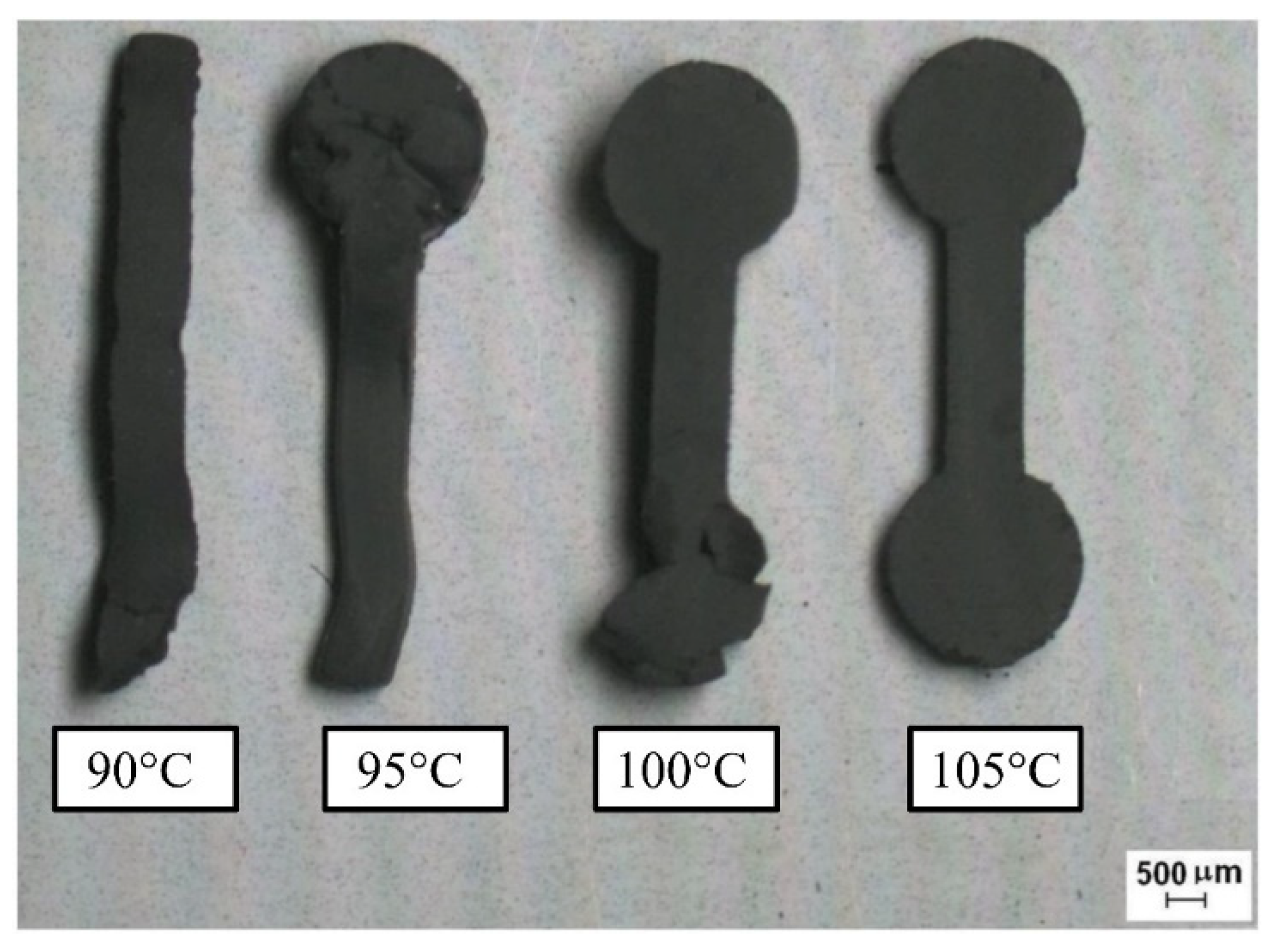
Figure 4. Green parts at different mold temperatures. Reproduced with permission from reference [20], copyright © 2014 Elsevier B.V.
According to the research by other authors [31][32], the defects that surfaced during debinding or sintering were not always caused by those steps but could instead have their roots in injection molding. Molding flaws can be fixed by changing the molding parameters. Despite having no apparent imperfections, molded objects may still experience dimensional variation or distortion during sintering because of their density gradient. Sardarian et al. [33] optimized the LPIM process parameters to fabricate alumina ceramics. An alumina feedstock with 60 vol.% powder was injected into the mold at temperatures and pressures of 70–100 °C and 0.1–0.6 MPa, respectively. Except for 70 °C and pressures less than 0.3 MPa, these temperatures and pressures were sufficient to fill the cavity. According to the findings, raising the injection temperature and pressure has a beneficial impact on how well the mold cavity is filled. Figure 5 shows the effect of the process parameters on the green density. The green density of the components is not significantly impacted by either the injection temperature or pressure. The variability of the obtained density increases since the error bars are larger at higher temperatures.
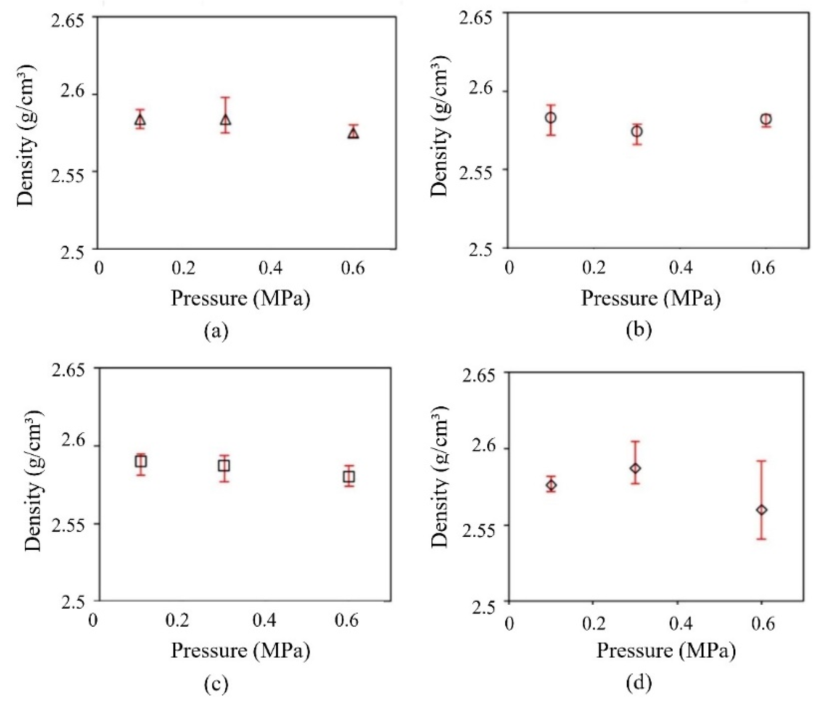
Figure 5. Effects of the pressure and temperature on the density of the green parts: (a) 70 °C; (b) 80 °C; (c) 90 °C; (d) 100 °C. Reproduced with permission from reference [33], copyright © 2016 Elsevier Ltd.
Utilizing injection molding at a temperature of 80 °C and a pressure of 0.6 MPa produced the best results. Variation in the green density of the components may have occurred because of void formation during the filling step when the parts were molded at high injection temperatures and pressures. The occurrence of jetting may be responsible for the void’s creation. The shrinkage linked to the brittle nature of the green parts is another crucial element of the LPIM process. As previously indicated, waxes are frequently added to LPIM feedstock to decrease the viscosity. Too much wax content in the feedstock can cause shrinkage when the injection mold cools and the part solidifies. Because of the range of applied pressure, approaches like the overshot are not feasible (usually under 0.7 MPa). The feeding gate typically hardens quickly, making pressure control challenging.
Costa et al. [2] investigated welding line formation in holes obtained by LPIM of ceramic parts. Injection molding and welding lines typically form due to the material flow being divided by an obstruction and its posterior junction [34][35][36]. Welding lines reduction is possible by using a low percentage of the waxes in the feedstock. In LPIM, which requires subsequent debinding and sintering, welding lines might cause stress concentration and crack formation.
3. Simulation
Mold filling is one of the most crucial processes in the PIM process that must be controlled to produce a complete mold filling and to avoid defects like voids, welding lines [37], jetting, warpage [38], fractures, and sinks [39].
Simulations and models used for plastic injection molding have also been applied to PIM. Nevertheless, the high powder content frequently results in changes that the models used in plastics neglect. Several cases exemplify the issues, including powder–binder separation at welding lines, significant inertial effects in the molding of tungsten alloys, and fast heat loss as in the molding of copper and aluminum nitride. Additionally, powder–binder combinations are extremely shear-sensitive. As a result, the computer simulations used to assist molding in the plastics industry need to be improved to work for LPIM. The improvements should include those feedstock characteristics in new PIM models for filling, packing, and cooling [40][41][42][43][44][45]. To optimize the process parameters and eliminate molding flaws, numerous physical characteristics, such as the material filling times, flow behavior, and injection pressure, have been effectively predicted using numerical simulations [46]. For metallic feedstocks, the injection stage has been modeled mostly for high-viscosity powder binder mixtures designed for the HPIM [42][47][48][49][50][51].
Simulations of mold filling, including jetting, filling time, and pressure distribution, were primarily done for ceramic-based feedstocks [52][53] in the LPIM process. However, few numerical models describing the injection stage for metallic-based LPIM feedstocks have been identified in the literature [54][55].
For example, Ghanmi and Demers [55] determined the moldability potential of a complex-shaped specimen made from titanium-based feedstock through numerical simulations. This study’s objective was to evaluate the effect of low-viscosity binder components on the moldability of LPIM titanium-based feedstocks and to anticipate the occurrence of defects using numerical simulations. They applied Moldflow to detect the high shear rate zones encountered by the feedstock, where laboratory testing confirmed the predicted segregation of 2 vol.%. However, computational models did not accurately anticipate the halo-shaped segregation pattern evident in the cross-section of the injected parts. In another study for metals, Azzouni et al. [54] examined the feasibility of simulating the mold-filling behavior of a 17-4PH stainless steel feedstock with the LPIM using the commercial program Autodesk Moldflow Synergy 2019. Since actual and simulated injections were conducted at a constant volumetric flow, the injected length and melt front velocity were not affected by the feedstock temperature but rather by the geometry of the mold cavity. In this regard, the injection length and melt front velocity predicted by the numerical model were in excellent agreement with experimental results, with a maximum relative divergence of 0.5% and 3.7%, respectively. In addition, they determined that the numerical model almost accurately represented the drop in injection pressure with an increase in melt temperature or an increase in mold cavity cross-section for filling stages below 75%.
Using Moldflow Synergy, Sardarian et al. [52][56] predicted the filling time and pressure for an alumina-based feedstock used in LPIM. The same study team also demonstrated Moldflow Synergy’s remarkable ability to comprehend better the impact of pressure, temperature, and flow rate on the jetting phenomena and improve injection settings [56]. Ben Trad et al. [21] proved Moldflow’s capacity to replicate the melt front velocity, injected length, filling time, and segregation phenomena in LPIM. The simulated injection pressures achieved by prior research teams have never been confirmed with actual measurements. Their study aims to validate the Moldflow modeling tool’s capacity to estimate the in-cavity pressure during the injection phase of LPIM metallic feedstock.
As previously mentioned, the incomplete filling is one imperfection typically resulting from a lack of fluidity in the feedstock or a too-narrow mold cross-section. Other causes of this problem include resin oxidation, improper injection-molding temperature, inadequate shot volume, and a low feedstock flow rate. Before solidification, the feedstock must fill the mold during the filling stage. The processing temperature and polymer flow rate may be excessively high to minimize unfilled regions, leading to more burr defects [57]. In this context, Yavari and Khorsand [58] conducted numerical and experimental research on separation, injection step, and imbalance filling in LPIM of ceramic components. SiC feedstock was injected at varying temperatures and flow rates. It was determined that the segregation and imbalance filling phenomena are more pronounced in thin-walled samples, but imbalance filling was not found in flexural specimens. Nevertheless, the thin-walled sample is considerably more sensitive to changes in flow rate and temperature. Thus, increasing the temperature, since the viscosity decreases, the binder flows ahead, and the solid loading is reduced. The separation phenomena enhanced as temperature and flow rate increased. Imbalanced filling, filling pattern, experiment findings, and segregation simulation were consistent.
This entry is adapted from the peer-reviewed paper 10.3390/ma16010379
References
- Radulovic, J. Powder injection moulding technology: Properties, possibilities and starting activities. Sci. Tech. Rev. 2015, 65, 20–28.
- Costa, C.A.; Michels, A.F.; Kipper, M.E. Kipper, Welding lines formation in holes obtained by low pressure injection molding of ceramic parts. Ceramica 2018, 64, 97–103.
- César, P.; Felix, G.; Blazdel, P.F.; Emílio, R.; Nogueira, F.Q. Production of complex parts by low-pressure injection molding of granite powders. part I-preparation of feedstock, injection and debinding. In Proceedings of the 1st Congresso Brasileiro de Engenharia de Fabricação—COBEF, Curitiba, Brazil, 2–4 April 2001.
- Liberati, J.F.; Araujo Filho, O.O.; Monteiro, W.A.; Esposito, I.M.; Nogueira, R.A.; Ambrosio Filho, F. Low-pressure injection molding processing of AISI T15 high speed steel powders. In Materials Science Forum; Trans Tech Publications Ltd.: Bäch, Switzerland, 2006; pp. 569–573.
- MI, P.; ID, P. Low Pressure Hot Molding Machine. U.S. Patent No. 4416603, 22 November 1983.
- Gonçalves, A.C. Metallic powder injection molding using low pressure. J. Mater. Process. Technol. 2001, 118, 193–198.
- Hiroaki c/o Pat. Lic.; Qual. Stand. Dept. Nishio, Takeshi c/o Pat. Lic.; Qual. Stand. Kawashima. Method for Casting Powder into a Compact and Apparatus Therefor. U.S. Patent EP19880115387, 24 May 1989.
- Yamada, K.; Saito, Y. Apparatus for Supplying Inorganic Slurry to an Injection Mold. U.S. Patent No. 5795601, 18 August 1998.
- Ivzhenko, V.V.; Popov, V.A.; Sarnavskaya, G.F. Powder metallurgy industry and managerial economics micro/nanosized refractory powder injection molding machine. Powder Metall. Met. Ceram. 2012, 51, 368–371.
- Yamamoto, K. Injection Molding Method and Injection Molding Device of Ceramics. U.S. Patent JP 2745513, 1989.
- Pompe, R.; Brandt, J. Goceram’s MEDPIMOULD technology offers cost-effective PIM production. Met. Powder Rep. 2001, 56, 14–17.
- Lamarre, S.G.; Demers, V.; Chatelain, J.F. Low-pressure powder injection molding using an innovative injection press concept. Int. J. Adv. Manuf. Technol. 2017, 91, 2595–2605.
- Bauer, W.; Knitter, R. Development of a rapid prototyping process chain for the production of ceramic microcomponents. J. Mater. Sci. 2002, 37, 3127–3140.
- Müller, M.; Bauer, W. Low-pressure injection molding of ceramic micro devices using sub-micron and nano scaled powders. Multi-Mater. Micro Manuf. 2005, 1–4.
- Çetinel, F.A.; Müller, M.; Rögner, J.; Bauer, W.; Hausselt, J. Influence of dispersant on rheology of zirconia-paraffin feedstocks and mechanical properties of micro parts fabricated via LPIM. Adv. Process. Manuf. Technol. Struct. Multifunct. Mater. IV 2010, 31, 31–43.
- Hausnerova, B.; Marcanikova, L.; Filip, P.; Saha, P. Optimization of powder injection molding of feedstock based on aluminum oxide and multicomponent water-soluble polymer binder. Polym. Eng. Sci. 2011, 51, 1376–1382.
- Amin, S.Y.M.; Muhamad, N.; Jamaludin, K.R. Optimization of injection molding parameters for WC-Co feedstocks. J. Teknol. 2013, 63, 1.
- Md Ani, S.; Muchtar, A.; Muhamad, N.; Ghani, J.A. Fabrication of zirconia-toughened alumina parts by powder injection molding process: Optimized processing parameters. Ceram. Int. 2014, 40, 273–280.
- Loebbecke, B.; Knitter, R.; Haußelt, J. Rheological properties of alumina feedstocks for the low-pressure injection moulding process. J. Eur. Ceram. Soc. 2009, 29, 1595–1602.
- Fayyaz, A.; Muhamad, N.; Sulong, A.B.; Rajabi, J.; Wong, Y.N. Fabrication of cemented tungsten carbide components by micro-powder injection moulding. J. Mater. Process. Technol. 2014, 214, 1436–1444.
- Ben Trad, M.A.; Demers, V.; Côté, M.; Sardarian, L. Dufresne, Numerical simulation and experimental investigation of mold filling and segregation in low-pressure powder injection molding of metallic feedstock. Adv. Powder Technol. 2020, 31, 1349–1358.
- Medvedovski, E.; Peltsman, M. Low pressure injection moulding mass production technology of complex shape advanced ceramic components. Adv. Appl. Ceram. 2012, 111, 333–344.
- Moghadam, M.S.; Fayyaz, A.; Ardestani, M. Fabrication of titanium components by low-pressure powder injection moulding using hydride-dehydride titanium powder. Powder Technol. 2021, 377, 70–79.
- Piotter, V.; Bauer, W.; Knitter, R.; Mueller, M.; Mueller, T.; Plewa, K. Powder injection moulding of metallic and ceramic micro parts. Microsyst. Technol. 2011, 17, 251.
- Nor, N.H.M.; Muhamad, N.; Ahmad, S.; Ibrahim, M.H.I.; Harun, M.R.; Jamaludin, K.R. Parameter optimization of injection molding Ti-6Al-4V powder and palm stearin binder system for highest green density using taguchi method. Key Eng. Mater. 2010, 443, 69–74.
- Chua Abdullah, M.I.H.; Sulong, A.B.; Muhamad, N.; Abdullah, M.F.; Che Haron, C.H. Optimization of injection parameters using 16µm stainless steel powder (SS316L) at 63 Vol. %, 63.5 Vol. % and 64 Vol. % powder loading by taguchi method for metal injection molding. Key Eng. Mater. 2011, 471–472, 558–562.
- Fang, W.; He, X.; Zhang, R.; Yang, S.; Qu, X. The effects of filling patterns on the powder–binder separation in powder injection molding. Powder Technol. 2014, 256, 367–376.
- Liu, Z.Y.; Loh, N.H.; Tor, S.B.; Khor, K.A. Characterization of powder injection molding feedstock. Mater. Charact. 2002, 49, 313–320.
- Aggarwal, G.; Park, S.J.; Smid, I. of niobium powder injection molding: Part I. Feedstock and injection molding. Int. J. Refract. Met. Hard Mater. 2006, 24, 253–262.
- Aslam, M.; Ahmad, F.; Yusoff, P.S.M.B.M.; Altaf, K.; Omar, M.A.; German, R.M. Powder injection molding of biocompatible stainless steel biodevices. Powder Technol. 2016, 295, 84–95.
- Hu, S.C.; Hwang, K.S. Length change and deformation of powder injection–molded compacts during solvent debinding. Metall. Mater. Trans. A 2000, 31, 2–7.
- Shivashankar, T.S.; Enneti, R.K.; Park, S.-J.; German, R.M.; Atre, S.V. The effects of material attributes on powder–binder separation phenomena in powder injection molding. Powder Technol. 2013, 243, 79–84.
- Sardarian, M.; Mirzaee, O.; Habibolahzadeh, A. Influence of injection temperature and pressure on the properties of alumina parts fabricated by low pressure injection molding (LPIM). Ceram. Int. 2017, 43, 4785–4793.
- Krug, S.; Evans, J.R.G.; ter Maat, J.H.H. Jetting and weld lines in ceramic injection moulding. Br. Ceram. Trans. 1999, 98, 178–181.
- Wu, C.-H.; Liang, W.-J. Effects of geometry and injection-molding parameters on weld-line strength. Polym. Eng. Sci. 2005, 45, 1021–1030.
- Beck, M.; Piotter, V.; Ruprecht, R.; Haußelt, J. Dimensional tolerances of micro precision parts made by ceramic injection moulding. In 4M 2006; Menz, W., Dimov, S., Fillon, B., Eds.; Elsevier: Oxford, UK, 2006; pp. 135–138.
- Minh, P.S.; Nguyen, V.-T.; Nguyen, V.T.; Uyen, T.M.T.; Do, T.T.; Nguyen, V.T.T. Nguyen, Study on the fatigue strength of welding line in injection molding products under different tensile conditions. Micromachines 2022, 13, 1890.
- Huynh, T.T.; Nguyen, T.V.T.; Nguyen, Q.M.; Nguyen, T.K. Minimizing warpage for macro-size fused deposition modeling parts. Comput. Mater. Contin. 2021, 68, 2913–2923.
- Keshavarz Panahi, A.; Mianajiy, H.; Miandoabchi, E.; Hussaini Fareed, M. Optimization of the powder injection molding process parameters using the sequential simplex algorithm and sensitivity analysis. J. Manuf. Sci. Eng. 2013, 135, 011006.
- Jiang, B.; Zhong, J.; Huang, B.; Qu, X.; Li, Y. Element modeling of FEM on the pressure field in the powder injection mold filling process. J. Mater. Process. Technol. 2003, 137, 74–77.
- Fu, G.; Tor, S.B.; Loh, N.H.; Tay, B.Y.; Hardt, D.E. The demolding of powder injection molded micro-structures: Analysis, simulation and experiment. J. Micromech. Microeng. 2008, 18, 75024.
- Zheng, Z.; Xia, W.; Zhou, Z.; Zhu, Q. Numerical simulation of tungsten alloy in powder injection molding process. Trans. Nonferrous Met. Soc. China. 2008, 18, 1209–1215.
- Kate, K.H.; Enneti, R.K.; McCabe, T.; Atre, S.V. Simulations and injection molding experiments for aluminum nitride feedstock. Ceram. Int. 2016, 42, 194–203.
- Duretek, I.; Holzer, C. Material flow data for numerical simulation of powder injection molding. J. Phys. Conf. Ser. 2017, 790, 12007.
- Yavari, R.; Khorsand, H.; Sardarian, M. Simulation and modeling of macro and micro components produced by powder injection molding: A review. Polyolefins J. 2019, 7, 45–60.
- Thornagel, M. Simulating flow can help avoid mould mistakes. Met. Powder Rep. 2010, 65, 26–29.
- Bilovol, V.V.; Kowalski, L.; Duszczyk, J.; Katgerman, L. The effect of constitutive description of PIM feedstock viscosity in numerical analysis of the powder injection moulding process. J. Mater. Process. Technol. 2006, 178, 194–199.
- Ilinca, F.; Hétu, J.-F.; Derdouri, A.; Stevenson, J. Metal injection molding: 3D modeling of nonisothermal filling. Polym. Eng. Sci. 2002, 42, 760–770.
- Ahn, S.; Chung, S.T.; Atre, S.V.; Park, S.J.; German, R.M. Integrated filling, packing and cooling CAE analysis of powder injection moulding parts. Powder Metall. 2008, 51, 318–326.
- Bilovol, V.V.; Kowalski, L.; Duszczyk, J.; Katgerman, L. Comparison of numerical codes for simulation of powder injection moulding. Powder Metall. 2003, 46, 55–60.
- Tseng, H.-C.; Chang, Y.-J.; Tien, C.-H.; Hsu, C.-H. Prediction of Powder Concentration for Filling Simulation of Metal Injection Molding. In Proceedings of the Annual Technical Conference, Las Vegas, NV, USA, 28–30 April 2014.
- Sardarian, M.; Mirzaee, O.; Habibolahzadeh, A. Mold filling simulation of low pressure injection molding (LPIM) of alumina: Effect of temperature and pressure. Ceram. Int. 2017, 43, 28–34.
- Zhang, M.M.; Lin, B. Simulation of ceramic injection molding for zirconia optical ferrule. Key Eng. Mater. 2007, 336–338, 997–1000.
- Azzouni, M.; Demers, V.; Dufresne, L. Mold filling simulation and experimental investigation of metallic feedstock used in low-pressure powder injection molding. Int. J. Mater. Form. 2021, 14, 961–972.
- Ghanmi, O.; Demers, V. Molding properties of titanium-based feedstock used in low-pressure powder injection molding. Powder Technol. 2021, 379, 515–525.
- Sardarian, M.; Mirzaee, O.; Habibolahzadeh, A. Numerical simulation and experimental investigation on jetting phenomenon in low pressure injection molding (LPIM) of alumina. J. Mater. Process. Technol. 2017, 243, 374–380.
- Shin, H.; Park, E.-S. Analysis of incomplete filling defect for injection-molded air cleaner cover using moldflow simulation. J. Polym. 2013, 2013, 720209.
- Yavari, R.; Khorsand, H. Numerical and experimental study of injection step, separation, and imbalance filling in low pressure injection molding of ceramic components. J. Eur. Ceram. Soc. 2021, 41, 6915–6924.
This entry is offline, you can click here to edit this entry!