Your browser does not fully support modern features. Please upgrade for a smoother experience.
Please note this is an old version of this entry, which may differ significantly from the current revision.
Subjects:
Energy & Fuels
|
Transportation
With the development of the global economy and the increase in environmental awareness, energy technology in transportation, especially the application of energy storage technology in rail transportation, has become a key area of research. Rail transportation systems are characterized by high energy consumption and poor power quality due to the more flexible regulation capability of energy storage technology in these aspects.
- energy storage technology
- rail transit
- battery
- supercapacitor
- flywheel
1. Introduction
In the last decade, energy storage technology has been extensively researched and developed in the long term [1,2,3,4,5,6,7]. Energy storage technology is no longer limited to being a mobile power source. It has many applications in all aspects of the power system. For the power generation side, energy storage units consume renewable energy and provide virtual rotational inertia to the power system as backup capacity on the grid side. Energy storage units are mainly used for frequency regulation of the power system and to achieve spatial and temporal load balancing. For the customer side, energy storage units are mainly used for emergency backup and tariff management, and energy storage technology can also improve the power quality on the customer side.
With the development of power transmission technology and power electronics, the electrification of rail transit has become a vital crossover direction and a hot technological growth point in the transport sector and the electrical sector [8,9,10]. On the one hand, electrified drives reduce the use of mechanical structures such as drive bearings and internal combustion engines, reducing the size of the powertrain. The superior speed control performance of electric motors is unmatched by internal combustion engines, which brings technical advantages to the performance indicators of electrified transport. On the other hand, transportation electrification reduces the direct use of fossil fuels and greenhouse gas emissions, achieving good environmental benefits. The cost of power transmission is lower than that of fossil fuel transportation, which significantly reduces the energy cost of electrified transportation.
The electrification of transportation has strengthened the connection between the power and rail transportation systems. The reliability and economy of power supply have become essential factors in transportation. By adding energy storage to the power supply system of railways, energy efficiency can be increased, and the impact of power system failures can be reduced.
The application of energy storage in transport systems has been studied to some extent. Due to the mobility and off-grid operation of energy storage systems, electric vehicles with energy storage units at their core are gaining ground in the long term [11,12,13,14,15]. However, the energy storage application in rail transit is still in its infancy. The electrified rail system is closely linked to the grid; its power supply system is integral to the grid. The power supply system of railways has a higher power rating than other modes of transport, and the load characteristics are intermittent and shocking. For these reasons, using energy storage technology in rail transit has unique characteristics.
2. Rail Transit Demanded by Energy Challenges
With the increasing electrification of rail transit, the speed of trains is gradually increasing, while energy consumption is increasing. As a result, rail transit is facing several challenges in the energy sector, such as the additional load from rail electrification, power fluctuations, and voltage dips caused by train operating moments [10,11].
Traction power grids can be classified according to the type of buses as DC traction power network and AC traction power network.
The DC traction network is the typical traction grid structure of a metro. The system consists of a grid AC bus and a supply DC bus, with the metro trains being supplied directly from the DC bus. As the metro usually contains two trains opposite each other, the metro’s DC traction power supply system consists of two parallel DC buses. Metro systems are typically supplied from the national electricity grid and use rectifier substations to convert AC voltage into 750, 1500, or 3000 V DC voltage to power the trains. Figure 1 shows the typical DC traction power network with multi-trains.
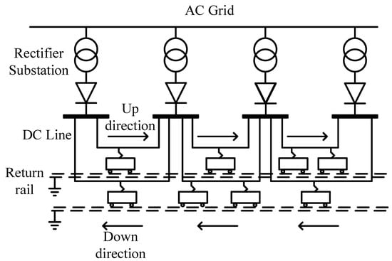
Figure 1. The typical DC traction power network with multi-trains.
The DC power supply system is mainly used in urban rail transit, which uses the bilateral power supply and has a small power supply range. The topology of urban rail transit and the possible access location of the ground energy storage system is shown in Figure 2. There are mainly two kinds of loads in the urban rail power supply system, station load and traction load, and the existing research is summarized.
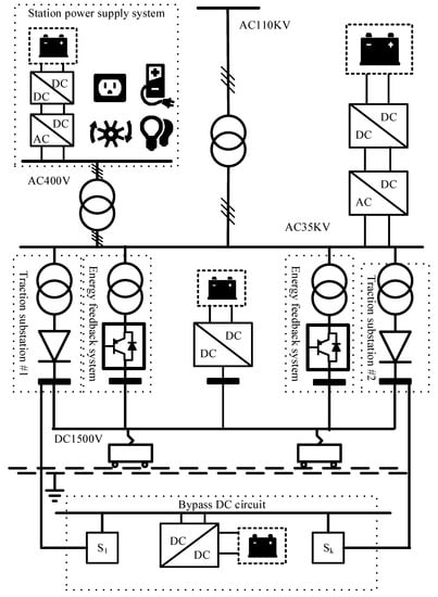
Figure 2. The DC traction energy system topology.
When the energy storage system selects the AC400 V side or AC35 kV side for grid connection, it can realize the interaction between AC and DC grids through the energy feeder system. It can supply energy to station loads and utility loads. The minor network loss makes DC-side configuration energy storage the focus of research for rail transit configuration energy storage. The conventional energy storage configuration contains two types: the reversible substations and the railroad line configuration energy storage. The conventional energy storage configuration consists of two types: substation configuration storage and roadside ESS.
Reversible substations are obtained by configuring energy storage in the traction grid substation [16]. This option has relatively low safety constraints and construction conditions and only needs to meet the general substation energy storage construction program. The reversible substation can provide energy storage for trains throughout the zone and does not require the railway to be shut down during maintenance. However, this technical solution lacks voltage stabilization, and the storage capacity needs to be determined in conjunction with the train operating schedule. The reversible substation can participate in the grid’s electricity trading, making the solution cost recovery possible. In addition, the maturity of the technology makes the application of this solution economical.
The roadside bypass ESS is another energy storage arrangement that places the storage units along the traction power lines alongside the tracks [17,18]. The roadside ESS can provide energy storage for internal trains within a certain zone to smooth out energy fluctuations within a certain zone. The advantage of this solution is that a single energy storage unit can be used for multiple trains and does not affect rail operations during maintenance. Roadside ESSs can significantly suppress voltage dips within the zone, but incur additional energy losses due to the need to use the traction system overhead lines to transfer energy. This solution requires a smaller number of energy storage units. It is less expensive overall, but it requires the energy storage to be pre-capacitated to consider the operating characteristics of the inter-district trains. This solution requires fewer energy storage units and is less costly overall, but it requires planning for energy storage capacity about the operating characteristics of the inter-district trains.
The AC traction network is the typical traction grid structure of railways. The AC traction power network supplies the trains via AC busbars based on traction transformers. The traction transformer is a step-down transformer as the grid supplying the traction system has voltage levels of 110 kV, 220 kV, and 330 kV, and the trains are supplied at 27.5 kV. There are three common forms of traction transformer wiring: v/v transformers, SCOTT transformers, and YNd11 transformers [19,20]. Figure 3 shows the typical AC traction power network with multi-trains.
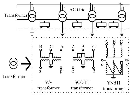
Figure 3. The typical AC traction power network with multi-trains.
The energy storage system can be configured with the station power system or an energy feedback device in AC rail power supply systems such as Figure 4. AC rail transit substations can be divided into two types, same-phase power supply substations, and staggered-phase power supply substations [21,22,23,24]. In the same phase power supply substation, the role of the energy storage system is similar to that of the DC power supply system, which is mainly used to regulate power; in the wrong phase substation, the role of energy storage is mainly to balance the power between phases.
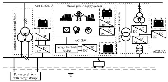
Figure 4. The AC traction energy system topology.
The DC traction and AC traction power supply have structural similarities. However, the busbar structures are different, and their energy storage devices have a similar system structure, differing only slightly in technical details.
This entry is adapted from the peer-reviewed paper 10.3390/wevj14010003
This entry is offline, you can click here to edit this entry!