Triply Periodic Minimal Surfaces (TPMS) are a kind of periodic implicit surface with zero mean curvature, that is, the surfaces that locally minimize surface area for a given boundary. The TPMS is composed of infinite, non-self-intersecting, periodic surfaces in three principal directions. The TPMS networks as repeated lattice structures have attracted much research interest because they have shown better mechanical performance, mass transfer, and thermal conductivity than conventional and strut-based structures, which have been employed in different disciplines. With excellent performances in the TPMS architectures, current works have investigated the TPMS structures to utilize in a wide range of applications.
- triply periodic minimal surfaces
- internal cooling
- heat transfer
1. Introduction
Additive manufacturing (AM) reduces the limitations in the fabrication of complex lattice structures. A variety of design tools are rapidly developed to facilitate the design of geometrically complex structures and allow designers to realize complicated models. Weight, volume, and manufacturing cost reductions are some benefits of AM over conventional manufacturing [1][2][3][4]. Among the lattice structures, architected materials with topologies based on Triply Periodic Minimal Surfaces (TPMS) have attracted much attention due to their mathematically controlled topologies and their excellent physical and mechanical properties.
The TPMS is composed of infinite, non-self-intersecting, periodic surfaces in three principal directions. Schwarz discovered the first example of TPMS was the Diamond minimal surface (Figure 1a) in 1865 [5]. Later, his student, Neovius, discovered the Neovius surface (Figure 1b) in 1883 [6]. They further discovered several minimal surfaces, e.g., the Primitive (Figure 1c). Almost a century later, in 1970, Schoen introduced various types of minimal surfaces, and the Gyroid minimal surface (Figure 1d) was the most famous [7]. The TPMS is characterized as a minimal surface because the curvature along the principal curvature planes is equal and opposite at every point, resulting in a mean curvature of zero.
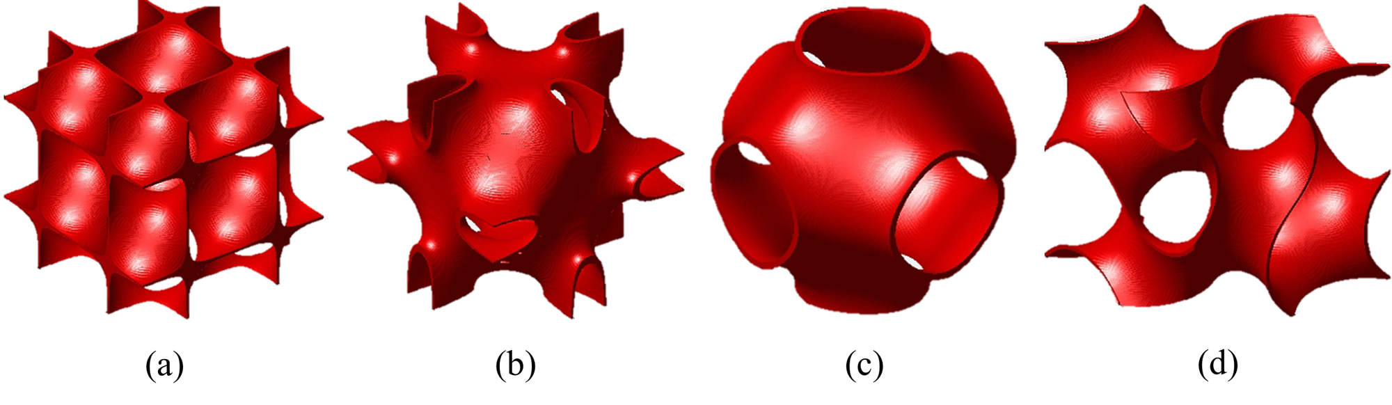
Figure 1 Minimal surfaces (a) Diamond; (b) Neovius; (c) Primitive; (d) Gyroid.
The TPMS is composed of infinite, non-self-intersecting, periodic surfaces in three principal directions. Schwarz discovered the first example of TPMS was the Diamond minimal surface (Figure 1a) in 1865 [5]. Later, his student, Neovius, discovered the Neovius surface (Figure 1b) in 1883 [6]. They further discovered several minimal surfaces, e.g., the Primitive (Figure 1c). Almost a century later, in 1970, Schoen introduced various types of minimal surfaces, and the Gyroid minimal surface (Figure 1d) was the most famous [7]. The TPMS is characterized as a minimal surface because the curvature along the principal curvature planes is equal and opposite at every point, resulting in a mean curvature of zero.
The level-set equation derived from a sum defined in terms of the Fourier is the most widely employed method to create minimal surface-like lattices. The level-set equations are a group of three-dimensional trigonometric functions that satisfy the equality criterion ϕ(x,y,z) = c. The level-set equations of Schwarz-Diamond (Diamond), Schoen-Gyroid (Gyroid), and Schoen-I-graph and Wrapped Package (IWP), typically found in the literature, are described in Equations (1–3).
Diamond: cos(2απx)cos(2βπy)cos(2γπz)−sin(2απx)sin(2βπy)sin(2γπz) = c (1)
Gyroid: sin(2απx)cos(2βπy) + sin(2βπy)cos(2απx) + sin(2γπz)cos(2απx) = c (2)
IWP: 2(cos(2απx)cos(2βπy) + cos(2βπy)cos(2γπz) + cos(2γπz)cos(2απx)−(cos 2(2απx) + cos 2(2βπy) + cos 2(2γπz)) = c (3)
where α, β, and γ denote constants related to the unit cell size (L) in x, y and z, respectively; c is the offset parameter, which equals zero for a single unit cell of the TPMS.
Two approaches can create the TPMS lattices based on the minimal surfaces. The first approach is achieved by considering the volume bound by the minimal surface to create the solid-based TPMS lattice, also known as the skeleton-based TPMS structure (Figure 2a). The second one is created by offsetting the minimal surface along its normal direction to create a double surface. This surface is known as the sheet-based TPMS lattice (Figure 2b). With these smooth curvatures, the TPMS-based structures can eliminate the stress concentrations commonly found in other structures.
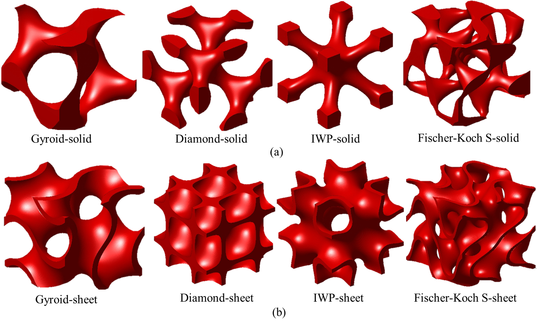
Figure 2 Examples of solid- and sheet-based TPMS lattices.
2. TPMS-related investigations
2.1 Mechanical performances
To demonstrate the merits of the TPMS-based structures, the performances of the TPMS-based structures are analyzed and compared with other structures. Among the performances in different fields, most of the research has focused on mechanical performances. Speirs et al. [8] reported that TPMS-based structures acquired superior fatigue resistance compared to the octahedron unit owing to smooth surfaces without nodal points. Khan et al. [9] demonstrated that the sheet-IWP structures exhibited superior viscoelastic behaviors under uniaxial loading than other lattice-frame materials. Wang et al. [10] presented that the sheet-Gyroid structure obtained the best stability and exhibited the widest range of mechanical properties compared to cubic and octet-strut-based structures. Teng et al. [11] reported that the sheet-Gyroid structure outperformed the BCC and truss lattice structures in stiffness, yield stress, and toughness, as shown in Figure 3. Overall, the TPMS-based structures provide better mechanical performance than the strut-based structures. Thus, the TPMS structures, especially the sheet-based ones, can be employed in different disciplines requiring high mechanical strength.
![Normalized mechanical properties of the Gyroid, BCC, Truss and Primitive lattices with respect to the wall thickness, adapted from [11].](/media/item_content/202212/figure3-63a55d0c8fa8a.png)
Figure 3 Normalized mechanical properties of the Gyroid, BCC, Truss and Primitive lattices with respect to the wall thickness, adapted from Teng et al. [11]
2.2 Mass transfer
The TPMS structures have interconnected curved walls with non-tortuous pores, which are appropriate for mass transfer and permeability applications. From the flow perspective, previous studies have focused on permeability and wall shear stress. Still, the flow considered in these investigations was mainly achieved in the Darcy regime, and the non-linear inertial effects were negligible. Ali et al. [12] reported that the sheet-Gyroid structure showed higher wall shear stress than the lattice-based models in the same porosity but generated comparable fluid permeability. Montazerian et al. [13] studied cylindrical ducts of different lattice- and TPMS-based scaffolds. They showed that the TPMS-based scaffolds, especially the solid-IWP structure, were more permeable than lattice-based ones in the longitudinal fluid flow direction, as presented in Figure 4. Also, the TPMS-based scaffolds within a wide range of porosity exhibited higher normalized permeability values than the fiber-based structures [14]. Even though the porosity of the fiber-based structure increased the permeability, the tortuosity was significantly decreased [15], which negatively affected the fluid mixing and heat transfer performance.
![Normalized longitudinal permeability versus porosity for different lattices, adapted from Montazerian et al. [13].](/media/item_content/202212/figure4-63a673e10aa09.png)
Figure 4 Normalized longitudinal permeability versus porosity for different lattices, adapted from Montazerian et al. [13].
2.3 Thermal conductivity
Many designers have tested the thermal conductivity of different TPMS-based structures. According to the experimental results by Wang et al. [16], the sheet-FRD structures achieved 103% higher thermal conductivity than the commercial stochastic foams with the same porosity. The sheet-TPMS structures also provide better thermal conductivity than the fiber-based structure since the normalized thermal conductivity values of the fiber-based porous media considerably varied with the fiber direction [17]. The main reason for the higher thermal conductivity in the sheet-TPMS structures was the excellent connectivity of the interconnected curvature.
Also, it has been reported that effective thermal conductivity strongly depends on the topologies. Qureshi et al. [18] presented that the sheet-Primitive structure exhibited the highest value, followed by sheet-IWP and sheet-Gyroid structures, whereas the Kevin cell model caused the lowest value. Smith et al. [19] concluded that the thermal conductivity of the TPMS-based structures was inversely proportional to the surface area-to-volume ratio. However, the thermal performance of cooling channels was typically proportional to surface areas for convective heat transfer. Overall, the thermal conductivity for most sheet-TPMS structures is similar, significantly higher than conventionally stochastic metal foams and lattice-frame materials, as shown in Figure 5.
![Normalized thermal conductivity for different lattices. Octet [20], Rhombi-Octet [21], Solid-Gyroid [22], Solid-Primitive[22], Sheet-CLP [22], Sheet-Neovius [22], Sheet-Fischer Koch S [22], Stochastic metal foam (Al) [23], Stochastic metal foam (FeCrAl) [24].](/media/item_content/202212/figure5-63a677d57d6d9.png)
Figure 5 Normalized thermal conductivity for different lattices. Octet [20], Rhombi-Octet [21], Solid-Gyroid [22], Solid-Primitive [22], Sheet-CLP [22], Sheet-Neovius [22], Sheet-Fischer Koch S [22], Stochastic metal foam (Al) [23], Stochastic metal foam (FeCrAl) [24].
2.4 Forced convective heat transfer
Unlike conventional pin-shaped heat sinks, the heat sinks with TPMS structures have a more complex geometry, forcing the fluid to change trajectory as it flows past the heated area [25][26]. The large surface area per unit volume, smooth curved wall, and complex topology qualify the TPMS-based structures to be examined as high-performance heat sinks. Moreover, being mathematically realized, the complexity level of the TPMS-based heat sinks can be controlled to optimize thermal performance.
To compare the heat transfer performance of TPMS-based structures, the globally averaged Nusselt number (Nu) of the TPMS-based structures and different cooling geometries, including dimples [27], ribs [28], latticework structures [29], pin fins [21], and micro-lattice structures [21], is plotted in Figure 6. It is evident that the TPMS-based structures show higher globally averaged Nusselt numbers, especially for the solid-Diamond and solid-Gyroid structures than the other cooling geometries. At the Reynolds number (Re) of 8000, the globally averaged Nusselt number for the solid-Diamond structure is higher than the pin fins, BCC, Octa, Kagome and X-type lattices by about 73%, 35%, 98%, 53% and 25%, respectively. Among the TPMS-based structures, the sheet-Gyroid structure shows low values of the globally averaged Nusselt numbers. On average, the solid-Diamond and solid-Gyroid structures outperform the sheet-Gyroid structure by 1.27 and 1.23 times. This increase is due to the higher surface area intersecting the flow field. However, it has been observed that the sheet-Gyroid structure outperformed the solid-Gyroid structure at Re > 6800, attributed to the enhanced fluid mixing in the sheet-Gyroid structure.
![Comparisons of globally averaged Nusselt number of the TPMS structures with other cooling strategies. Dimples [27], Transverse ribs [28], Angled ribs [87], Latticework structures [29], Pin fins [21], BCC [21], Octa lattices [21], Kagome lattices [21], X-type lattices [21], Solid-Diamond structures [30,31], Sheet-Gyroid structures [31], Solid-Diamond structures [31], Solid-Gyroid structures [31].](/media/item_content/202212/figure6-63a6784df270f.png)
Figure 6 Comparisons of globally averaged Nusselt number of the TPMS structures with other cooling strategies. Dimples [27], Transverse ribs [28], Angled ribs [28], Latticework structures [29], Pin fins [21], BCC [21], Octa lattices [21], Kagome lattices [21], X-type lattices [21], Solid-Diamond structures [30][31], Sheet-Gyroid structures [31], Solid-Diamond structures [31], Solid-Gyroid structures [31].
The globally averaged Nusselt number ratio with friction factor ratios for different geometries are plotted in Figure 7 to compare the relative performance of the cooling structures. The results show that the solid-Diamond structure acquires the highest Nusselt number ratio, up to 8.0–10.0, with friction factor ratios between 55.0–75.0. The solid-Gyroid structure causes lower Nusselt number ratios to the solid-diamond structure with similar friction factor ratios. The sheet-Gyroid structure generates higher Nusselt number ratios than the micro-lattice structures but causes high friction factor ratios. Meanwhile, the dimples and ribs give the lowest Nusselt number ratios of about 1.5–2.0 while producing minor friction factor ratios between 1.2–3.0.
![Relative thermal performance for different cooling structures. Dimples [27], Transverse ribs [28], Angled ribs [87], Latticework structures [29], Pin fins [21], BCC [21], Octa lattices [21], Kagome lattices [21], X-type lattices [21], Solid-Diamond structures [31], Sheet-Gyroid structures [31], Solid-Diamond structures [31], Solid-Gyroid structures [31].](/media/item_content/202212/figure7-63a678bdc8fb3.png)
Figure 7 Relative thermal performance for different cooling structures. Dimples [27], Transverse ribs [28], Angled ribs [28], Latticework structures [29], Pin fins [21], BCC [21], Octa lattices [21], Kagome lattices [21], X-type lattices [21], Solid-Diamond structures [31], Sheet-Gyroid structures [31], Solid-Diamond structures [31], Solid-Gyroid structures [31].
2.5 Other applications
The TPMS-based structures are being examined as spacers in the membrane distillation to enhance heat and mass transfer [32][33]. It was found that the TPMS spacers enhanced the overall film heat transfer coefficient by 60% compared to the commercial spacers.
The larger surface area is essential for larger chemical reactions in catalytic sup-ports, fuel cells, and battery applications. Abu Al-Rub and Al-Ketan [34] proposed using TPMS-based structures as catalytic substrates. Al-Ketan et al. [35] examined the flow properties of the solid- and sheet-TPMS substrates and found that the CLP-based substrate exhibited a well-reduced pressure drop, while the sheet-Gyroid structure exhibited the highest value.
Different metallic TPMS-based structures have been used as thermal conductivity enhancers for organic PCMs (Phase Change Materials). It was found that the PCM embedded with the sheet-Primitive structure provided superiority in terms of heat transfer performance over the PCM-alone cases [36], as presented in Figure 8. Also, Quereshi et al. [37] reported that the sheet-TPMS structures showed enhanced heat transfer performance by increasing the average heat transfer coefficient and reducing the melting time of the PCM. Fan et al. [38] observed that integrating the TPMS structure in a PCM-based battery thermal management system (BTMS) achieved significant improvement in reducing the battery temperature. They further combined water as a working fluid for PCM/TPMS-based BTMS, and it was found that the average battery temperature was lower than without a cooling water system by about 40%, which eliminated the thermal saturation of PCM.
![Comparisons of heat flux and liquid fraction for PCM only and Primitive PCM, adapted from [36].](/media/item_content/202212/figure8-63a67fdd19d3d.png)
Figure 8 Comparisons of heat flux and liquid fraction for PCM only and Primitive PCM, adapted from [36].
Recently, Qureshi et al. [39] reported the utilization of TPMS architectures impregnated with PCM for high heat flux cooling applications for the first time. It was observed that the TPMS-based structures mitigated temperature under high heat flux conditions. Moreover, a change in heat sink material from aluminum powder (AlSi10Mg) to copper showed better temperature mitigation because of the favorable thermal conductivity.
Baobaid et al. [40] compared the solid-Diamond, solid-Gyroid and sheet-Gyroid structures for three boundary conditions. It was found that the sheet-Gyroid structure achieved superior thermal performance when opening the top and bottom surfaces of the enclosure. Still, its surface temperature was the highest when opening the sides and top surfaces. They summarized that the sheet-Gyroid structure with a larger surface area was opposed by the flow resistance inside the complex structure, causing a considerable decrease in thermal performance.
3. Effects of TPMS design variables on flow and heat transfer
3.1 Porosity
The porosity (ε) is defined as the fluid volume divided by the total volume of the considered system. It has been fixed at equivalent values to compare the effects of different TPMS topologies on flow and heat transfer performance. The porosity can also be set to the same values for the uniform or graded TPMS structures. Moreover, in many investigations, the porosity of the specific TPMS topology has been varied to observe the flow and heat transfer characteristics.
3.1.1 Equivalent porosity
Most research has analyzed the flow, heat and mass transfer under laminar flow regimes for the uniform porosity of different TPMS structures. For heat exchanger applications, Cheng et al. investigated the TPMS-based structures' morphology [41][42]. In the numerical model, the cold gas flowed in the TPMS-based structures and cooled the pore and solid matrix interface, which was heated with the constant heat flux. It was reported that the interstitial Nusselt number values for the sheet-Primitive structure increased slightly at higher Reynolds numbers. In contrast, the values for the sheet-Diamond, sheet-IWP, and sheet-Gyroid structures increased in a quasilinear manner since the complex curvatures broke the boundary layer. The sheet-IWP model achieved the highest heat transfer, while the sheet-Primitive model caused the lowest values. However, it can be expected that the sheet-Diamond structures could provide the highest values when the Reynolds number is larger than 200.
Kaur and Singh [43] compared the averaged heat transfer coefficient of the sheet-Gyroid and sheet-Primitive structures at an equivalent porosity for heat sink applications where the coolant flow passes the TPMS-based structure that was heated by a constant heat flux. The simulation results showed that the sheet-Gyroid structure provided a higher heat transfer than the sheet-Primitive structure. Moreover, the sheet-Gyroid structure outperformed the sheet-Primitive structure at specific pumping power conditions, even though it caused a high-pressure loss in the channel. Sreedhar et al. [33] compared different solid-based TPMS structures, i.e., Gyroid, Primitive, IWP, Fischer Koch S, and transverse Schwarz CLP (tCLP), at the Reynolds number of about 20–60. They reported that the solid-Gyroid structure considerably improved mass transfer and reduced pressure loss. Similar results were also acquired by Thomas et al. [44], which further found that the tCLP topology exhibited a superior overall film heat transfer coefficient to the other TPMS structures but caused the highest pressure loss in the system.
The flow characteristics and heat transfer performance of a cooling channel for heat sinks at a specific porosity have also been tested for turbulent flow regimes. Yinzheng et al. [45] analyzed the heat transfer performance of the solid-Gyroid, solid-Diamond, and solid-Primitive structures. The results showed that the solid-Diamond structure presented the highest heat transfer performance owing to its larger heat dissipation area. In contrast, the solid-Primitive structure showed the lowest flow resistance in the channel. Al-Ketan et al. [30] compared the heat transfer performances between the solid-Gyroid, solid-Diamond, and sheet-Gyroid structures in a cooling channel heated on 4-side walls at the Reynolds number of about 4000–65,000. It was found that the sheet-Gyroid structure achieved the highest convective heat transfer coefficient because of its complex curvature. Among these TPMS topologies, Khalil et al. [31] further observed that the solid-Diamond structure showed the best thermal performance as the Reynolds number increased owing to reasonably increased pressure loss and significantly increased heat transfer. In addition, the sheet-Gyroid structure showed the lowest in the comparison since it caused the highest-pressure loss in the system.
Al-Ketan et al. [30] explained that the pressure loss variation in the channel was due to the difference in pore size, as demonstrated in Figure 9, where the diameter of the maximum sphere (red sphere) passing through the smallest hole of the TPMS-based structure was employed to describe the pore size. It can be observed that the sheet-Gyroid structure, causing the highest pressure loss, has the smallest pore size, followed by the solid-Diamond and solid-Gyroid structures.
![Figure 9 The maximum sphere, passing through the smallest hole of different TPMS lattices: (a) Sheet-Gyroid structure; (b) Solid-Diamond structure; (c) Solid-Gyroid structure, adapted from [30]](/media/item_content/202212/figure9-63a680b2ae48b.png)
Figure 9 The maximum sphere, passing through the smallest hole of different TPMS lattices: (a) Sheet-Gyroid structure; (b) Solid-Diamond structure; (c) Solid-Gyroid structure, adapted from [30].
The effects of grading the porosity of the TPMS-based structures have also been examined in several studies for enhancing the thermal performance of cooling channels. Graded TPMS structure is the gradual increase or decrease of the TPMS porosity along the channel’s length, width, or height, which remains the same overall porosity as the uniform TPMS ones.
Qureshi et al. [46] showed that for the sheet-Primitive, sheet-Gyroid, and sheet-IWP structures, the gradually increased porosity along the flow direction outperformed the equivalent uniform and gradually decreased porosity models in terms of conductive and convective heat transfer performances. Moreover, Al-Ketan et al. [30] reported that the graded-solid Diamond structure with porosity varying from 80.0–82.5% along the flow direction under turbulent flow regimes reduced the pressure loss by about 27.6%, while the overall heat transfer coefficient decreased by only 15.7%.
Figure 10 shows the velocity vector for uniform and graded diamond-solid structures, investigated by Al-Ketan et al. [30]. As seen the Figure 10a, for the uniform structure, the velocity increases gradually due to the fluid expansion. In the case with negative grading porosity in Figure 10b, the velocity entering the high porosity structure is lower than the corresponding uniform one. This reduction is attributed to the small structure that lesser disturbs the incoming fluid. However, a higher velocity can be observed as the structure is larger downstream. The velocity distribution in this channel is non-uniform as compared to the others. For the case with a positive grading structure in Figure 10c, the velocity increases significantly when the fluid enters the low porosity structure. The velocity magnitude remains similar throughout the channel, indicating better uniformity distribution of the flow.
![Velocity vectors of the uniform and graded diamond-solid structures at Re = 65,326, studied by Al-Ketan et al. [30]](/media/item_content/202212/figure10-63a6810e4e8ee.png)
Figure 10 Velocity vectors of the uniform and graded diamond-solid structures at Re = 65,326, studied by Al-Ketan et al. [30]
The graded TPMS structures were conceived with reasonable heat transfer reductions but provide a better thermal performance of cooling channels. The graded TPMS-based structures improve thermal performance and show less material consumption in additive manufacturing, rendering lightweight cooling channels. However, the graded TPMS-based structures might not be better than the corresponding uniform ones for particular functions due to other important considerations, e.g., mechanical strength, hydraulic performance, etc. [47].
3.1.2 Varying the porosity
The porosity variation for a specific TPMS structure considerably affects the overall contact area, changing the flow, heat and mass transfer. Sreedhar et al. [33] varied the porosity of the solid-Gyroid structure in the range of 72–90%. It was reported that the solid-Gyroid model with larger porosity significantly improved mass transfer and lowered pressure loss. However, several studies observed that the convective heat transfer coefficient and friction factor inversely varies with the porosity of the sheet-TPMS structures [48][49].
Qureshi et al. [46] found that the reduction in porosity for the sheet-Primitive, sheet-Gyroid, and sheet-IWP structures considerably enhanced conductive and convective heat transfer. Similarly, Cheng et al. [41] reported that as the porosity increased for the sheet-IWP, sheet-Diamond, and sheet-Gyroid structures, the interstitial convective heat transfer coefficient decreased since the velocity dropped in the channel at the larger porosity. However, the convective heat transfer coefficient for the sheet-Primitive structure increased at the higher porosity values due to the larger heat transfer area, as shown in Figure 11.
![Effect of porosity on convective heat transfer coefficient for different TPMS structures at Re = 40, adapted from [41].](/media/item_content/202212/figure11-63a681a50d4f8.png)
Figure 11 Effect of porosity on convective heat transfer coefficient for different TPMS structures at Re = 40, adapted from [41].
3.2 Wall thickness
Concerning additive manufacturing for cooling channels, the relative wall thickness (t) of different TPMS topologies has been set to investigate the effects on the flow and heat transfer performance. It should be noted that due to topology differences, the values of porosity (ε), pore size (dpore), and surface area at c = 0 (ATPMS) are varied for each TPMS surface at a homogenous wall thickness and unit cell size [50], as shown in Figure 12. At the same wall thickness of t = 0.1 mm and unit cell size of L = 2.0 mm, the porosity, pore size, and surface area of TPMS varied significantly in different TPMS topologies. The sheet-Diamond structure has the largest surface area with the same pore size as the sheet-Gyroid structure, while the sheet-Primitive structure has the least area with the largest pore size.
![Variations in porosity, pore size, and the surface of TPMS at c = 0 at the wall thickness of t = 0.1 mm and unit cell size of L = 2.0 mm for a unit cell of sheet-based TPMS structures (The correlations for the porosity, pore size and surface area are provided by Poltue et al. [50]): (a) Sheet-Gyroid; (b) Sheet-Primitive; (c) Sheet-Diamond; (d) Sheet-IWP structures](/media/item_content/202212/figure12-63a68227bde40.png)
Figure 12 Variations in porosity, pore size, and the surface of TPMS at c = 0 at the wall thickness of t = 0.1 mm and unit cell size of L = 2.0 mm for a unit cell of sheet-based TPMS structures (The correlations for the porosity, pore size and surface area are provided by Poltue et al. [50]): (a) Sheet-Gyroid; (b) Sheet-Primitive; (c) Sheet-Diamond; (d) Sheet-IWP structures.
In the laminar flow regime 15, Femmer et al. [51] reported that at the same thickness of 0.4 mm, the heat exchanger with the sheet-Diamond structure achieved a higher heat transfer performance for inherent pressure loss compared to the sheet-Gyroid, sheet-IWP, and sheet-Primitive structures. Similar results were reported by Passos [48], in which the best thermal performance was found in the sheet-Diamond structure. Genç et al. [49] observed that at the lowest thickness of 0.16 mm, the friction factors of the sheet-Diamond structure generated the highest pressure loss compared to the sheet-Gyroid and sheet-Primitive structures. Moreover, the friction factor decreased with increasing the Reynolds number for all TPMS geometries.
Iyer et al. [52] reported that the sheet-Primitive structure caused the lowest Nusselt number values. In contrast, the sheet-Diamond structure had the best heat transfer performance, followed by the C(I2-Y**), as plotted in Figure 13a. For the friction factor, the sheet-Neovius structure caused the highest values, followed by the sheet-FRD structure, while the other TPMS structures provided a comparable pressure loss within the Reynolds numbers varying between 0–300, as illustrated in Figure 13b. They also reported that the predictions of the pressure losses are lower than Femmer et al. [51] and Kaur and Singh [43] because of smaller frictional pressure loss from the semi-infinite curvatures in their simulations.
![Comparisons of the Nusselt number and friction factor of different TPMS topologies for the same infinitesimally thin walls (The correlations are provided by Iyer et al. [52]): (a) Averaged Nusselt numbers; (b) Friction factors.](/media/item_content/202212/figure13-63a6829a37568.png)
Figure 13 Comparisons of the Nusselt number and friction factor of different TPMS topologies for the same infinitesimally thin walls (The correlations are provided by Iyer et al. [52]): (a) Averaged Nusselt numbers; (b) Friction factors.
For higher Reynolds numbers, Li et al. [53] compared the flow and heat transfer characteristics of the sheet-Gyroid and sheet-Diamond structures for a homogenous wall thickness of 0.7 mm. It was reported that the thermal performance of the sheet-Gyroid structure was higher than the sheet-Diamond model. The different results from the previous investigations [48][51] can be attributed to the large turbulent kinetic energy (TKE) generation due to the fluid mixing at high Reynolds numbers in the sheet-Gyroid structure. This intensive fluid mixing was preferable for heat transfer enhancement.
The different thicknesses of the sheet-Diamond structure on flow and heat transfer performance for a heat sink cooling channel under laminar flow were studied by Attarzadeh et al. [54]. They reported that the larger wall thickness provided a higher convective heat transfer coefficient; however, a considerably large wall thickness blocked the flow field, decreasing the thermal performance of the cooling channel. As shown in Figure 14, a continuous decay of reverse flow in the channel was observed, which reduced the pressure loss when decreasing wall thickness. The lowest thickness showed the best thermal performance due to low-pressure loss and a moderate increase in heat transfer in the channel.
![Demonstrations of reverse flow regions for small thickness (left) and large thickness (right) of the sheet-Diamond structure at a specific Reynolds number [54].](/media/item_content/202212/figure14-63a682fa40c4e.png)
Figure 14 Demonstrations of reverse flow regions for small thickness (left) and large thickness (right) of the sheet-Diamond structure at a specific Reynolds number [54].
Later, Attarzadeh et al. [55] studied a multi-objective optimization workflow based on a Genetic Algorithm for laminar flow to reveal the optimal configurations. The sheet-Gyroid structure was selected to study the TPMS design variables. It was observed that increasing wall thickness improved thermal performance. They also suggested that the pore size and the wall thickness of the TPMS structure were the most Pareto-sensitive in the optimization. It should be marked that the results did not conflict with the previous findings by Attarzadeh et al. [54] since the TPMS topologies and unit cell sizes employed in the study are different, presenting different results between them.
3.3 Unit cell size
The effects of unit cell size for the TPMS topologies on the flow and heat transfer performances are rarely found in the literature. Zimmer et al. [56] investigated the pressure loss in three different unit cell sizes of the sheet-Diamond structure at 8 mm, 4 mm, and 2 mm They reported that the largest unit cell sizes generated the low-pressure loss in the system, while the smallest one considerably increased pressure loss, particularly at higher velocities. Similarly, Al-Ketan et al. [35] found that at the same wall thickness of 0.6 mm, the sheet-Gyroid and sheet-Primitive structures with the smaller unit cell size caused higher pressure loss because of more complex geometries and lower porosities. Attarzadeh et al. [55] investigated three different cell sizes of the sheet-Gyroid structure in a cooling channel. They reported that decreasing the unit cell size improved the thermal performance of the heat exchanger. It can be deduced that a smaller unit cell size caused higher pressure loss due to the lower porosity but achieved higher heat transfer due to the larger specific surface areas (Sv), as shown in Figure 15.
![The sheet-Gyroid structures with different unit cell sizes at the same thickness of 0.6 mm, adapted from [35].](/media/item_content/202212/figure15-63a6836d5b959.png)
Figure 15 The sheet-Gyroid structures with different unit cell sizes at the same thickness of 0.6 mm, adapted from [35].
4. Conclusion
Extensive studies have been reviewed to show the effects on flow and heat transfer enhancement in cooling channels with triply periodic minimal surfaces (TPMS) from recent experimental and numerical studies. The extensive results include the effects of porosity on the flow field and heat transfer, followed by the effects of wall thickness and unit cell size. The main conclusions are drawn as follows:
- With the same porosity, more complex TPMS topologies, e.g., Diamond and Gyroid models, achieve high heat transfer as the Reynolds numbers increase but cause high-pressure loss. This increase is due to their tortuosity topologies and larger surface areas, considerably changing the flow characteristics. For heat sink applications, the graded TPMS-based structure along the flow direction provides better thermal performance than the uniform one due to decreased pressure loss with maintaining high heat transfer in the channel.
- The convective heat transfer coefficient and friction factor inversely change with the porosity for most of the sheet-TPMS structures, except for the Primitive model, because a large high-speed velocity area occurs in the lower porosity model along the flow direction, significantly interacting with the heating walls.
- Different TPMS topologies with the same wall thickness have different porosities and surface areas, leading to flow and heat transfer variation. Under laminar flow, the Diamond heat exchanger shows the best thermal performance, while for turbulent flow regimes, the Gyroid heat transfer obtains better because of increased turbulent kinetic energy. The larger wall thickness shows higher convective heat transfer and pressure loss; however, owing to the TPMS topologies and unit cell sizes, the wall thickness variation affect the flow field and heat transfer enhancement differently.
This entry is adapted from the peer-reviewed paper 10.3390/en15238994