Your browser does not fully support modern features. Please upgrade for a smoother experience.
Please note this is an old version of this entry, which may differ significantly from the current revision.
Thermal barrier coating (TBC) systems have presented an ongoing design issue in bids to improve the lifespan of coatings. A TBC can support an extended lifespan by repairing cracks between interfacial layers during high thermal exposure while at the same time increasing coating thickness. Two deposition techniques, atmospheric plasma spray and water-stabilized plasma spray (WSP), have been distinguished to understand mechanical and thermal performance based on their contrasting torch systems and microstructural characterization.
- thermal barrier coatings
- water-stabilized plasma spraying
- atmospheric plasma spraying
1. Introduction
Since the 1970s, new thermal barrier coating (TBC) developments have progressed through revolutionary deposition techniques. The criteria for novel materials to acquire low thermal conductivity with erosion and thermal shock resistance have also been explored [1]. The TBC system utilized for turbine engine components is made up of integral layers consisting of a bond coat and a topmost ceramic layer. These layers protect against harsh environments and exposure to constant high temperatures. The multilayer coatings are designed carefully to accentuate the temperature gradient property, subsequently extending the lifespan of the coatings. The design requirements for TBC and fabrication methods have been evolving and continuously in need of modification in tandem with the increasing thrust-to-weight ratio criteria, as depicted in Figure 1 [2]. As these multilayers within a TBC system can perform at their optimal requirements, the benefits of TBC do not only protect its lifespan against heat and corrosion. It took many engineering design procedures to optimize engine efficiency—the addition of a 7 wt.% Y2O3-stabilized ZrO2 (7YSZ)-coated turbine component permits the maximum allowable hot combustion gases without compromising the superalloy substrate. The discovery of this new material has been a significant step of improvement in tackling thermal efficiency while reducing fuel costs [3].
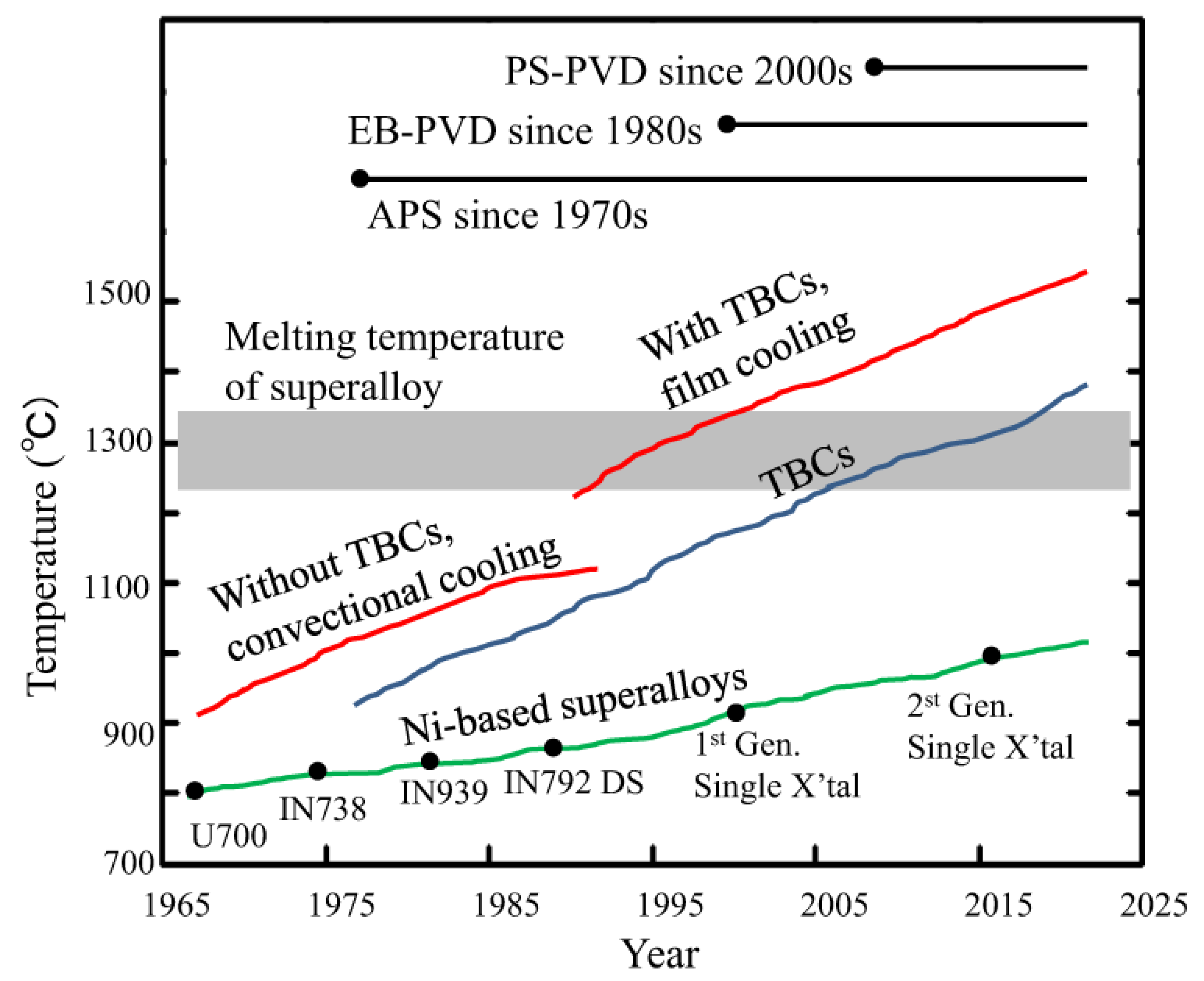
Figure 1. Modification of gas turbine engine from 1960s to current progression. Reprinted with permission from [2]. Copyright 2020 Springer Nature.
As illustrated in Figure 2, the TBC system comprises ceramic layers of 7YSZ, a thermally grown oxide (TGO), and a bond coat. The topcoat 7YSZ has a thickness range from 0.1 to 3 mm, providing adequate room for porosity to yield strain compliance [3]. The low-thermal-conductivity layer also hinders fast heat transfer activity into the superalloy substrate of the gas engine and protects against corrosion and erosion beneath it. Between the substrate and topcoat is a bond coat layer with a thickness range from 30 to 100 µm [3]. This intermediary layer supports adhesion in the TBC system. It also systematically controls the interdiffusion of elements between the topcoat and substrate to enhance the creep and thermal fatigue resistance. When the temperature exceeds 1000 K, a thin oxidation layer forms on the bond coat known as TGO [3]. The TGO is a 0.1 to 10 µm thick layer and governs by internal oxidation from the product of the hot gas that forms aluminum oxide (Al2O3). Due to the low-oxygen ionic diffusivity and its chemical stability, it aids as a protective alumina layer between the topcoat and substrate [4].
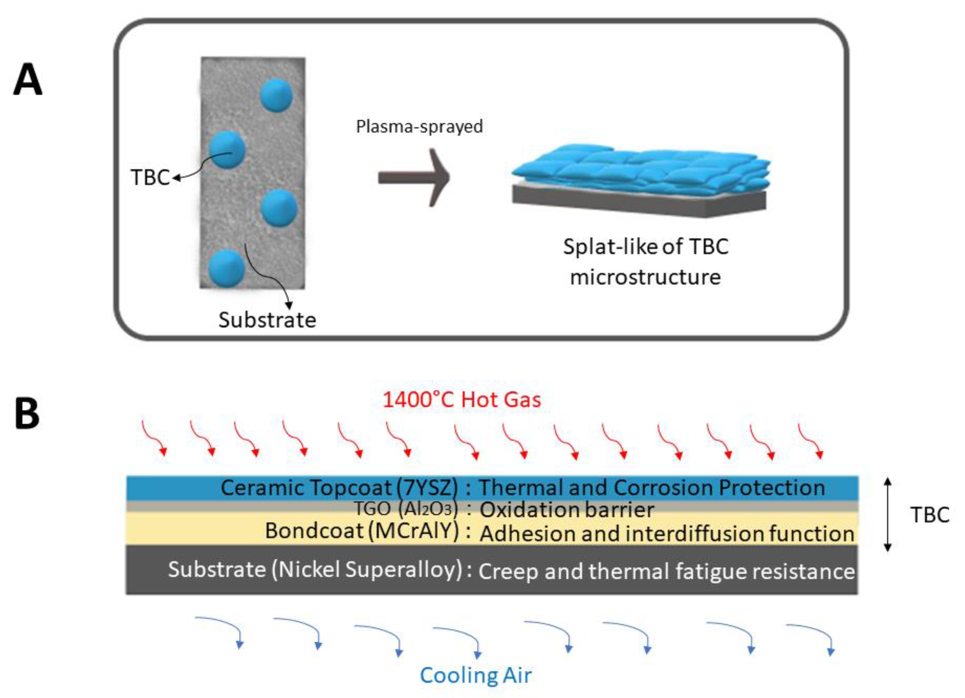
Figure 2. TBC coatings: (A) splat-like microstructure of plasma-sprayed deposition, and (B) the functional properties of TBC multilayer coatings.
2. Atmospheric Plasma Spray
Many research papers have shown that plasma-sprayed 7YSZ is prone to cracks within the TGO layer and the interfacial layer between TGO/YSZ or TGO/bond coat [5][6][7][8][9]. Due to the different thermal expansion stresses amongst these layers, the microcrack will propagate and unavoidably cause the spallation of the topcoat layer [10]. Other contributing factors also result from the stiffness of TBC due to sintering, creep, and stress relaxation between the bond coat and YSZ layer [10]. However, the major drawback of TBC coating failure through APS is its inability to accommodate strain, where microstructural morphology ranges from 10 to 15% porosity. As strain compliance reinforces porosity and microcracks, a study has shown that the erosion rate resulted in 125 g/kg when impacted at 90°. The outcome indicates poor erosion resistance due to failure around splat boundaries of the microcracks from APS deposition [11]. In addition, the microstructural grains from low-porosity coatings exhibited fine columnar grains due to impact-quenched and molten lamellae. The majority exhibited coarse equiaxed grains of various sizes due to unmelted or resolidified particles, as shown in Figure 3. [12]. After many thermal cycles, the TGO layer nearing its critical failure point will propagate and introduce long delamination cracks into the already-weakened YSZ layer. It was noted that short-range sintering is probably the main factor behind the observed formation of distributed fine porosity, hence favoring delamination crack progression [12].
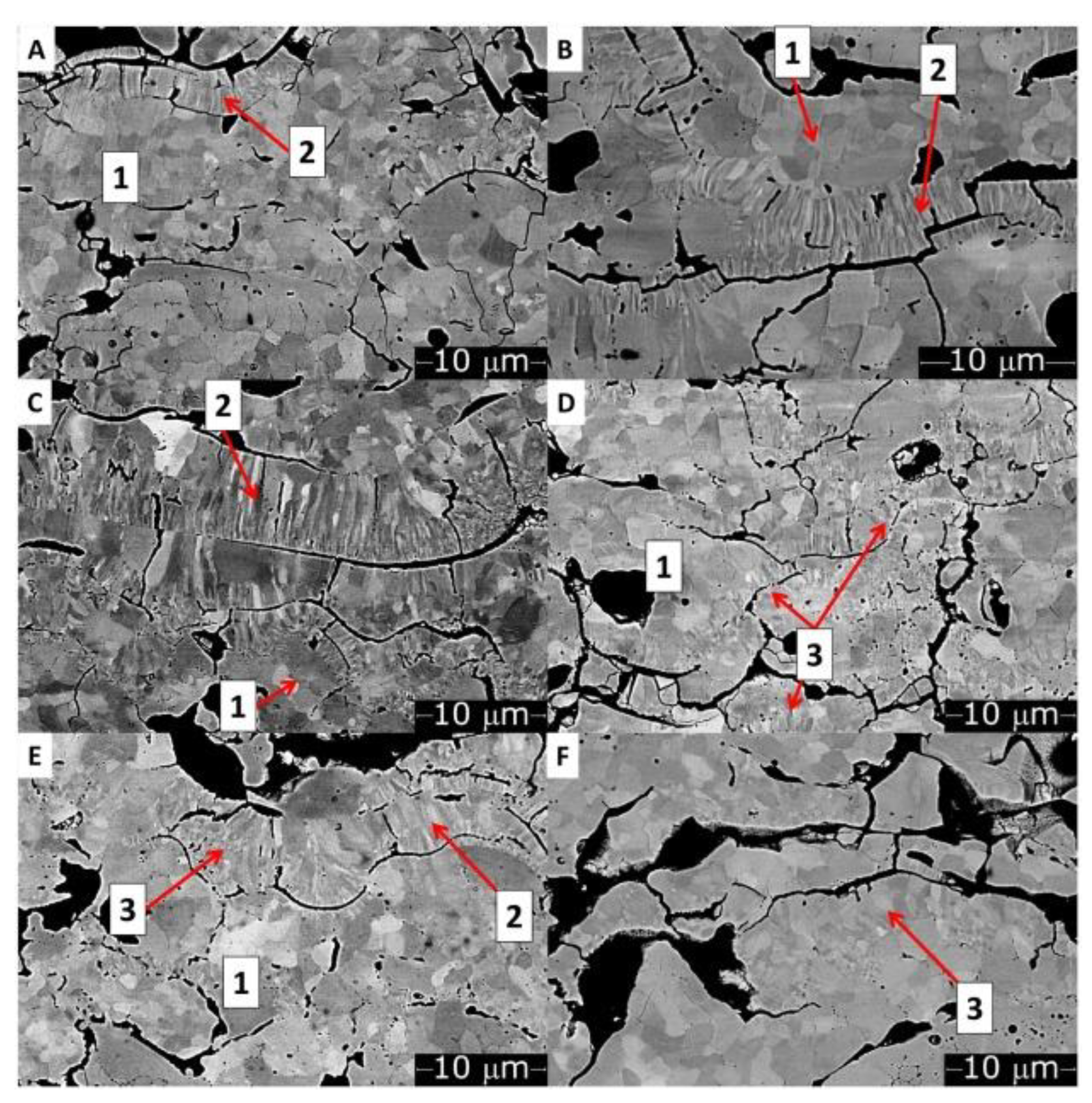
Figure 3. Low-porosity YSZ coating observed on BSE-SEM with equiaxed grains (Label 1), columnar grains (Label 2), and recrystallized columnar grains (Label 3). (A–F) represent the thermal cycles in increasing order. Reprinted with permission from [12]. Copyright 2019 Elsevier Ltd.
The microstructural features of TBC are influenced by its failure phenomenon. A lamellar structure forms when splats from APS condense into a structured layer [6]. The occurrence of pores induces fracture resistance and provides strain tolerance, while the splat interface initiates the beginning of TBC failure. The crack length at the flat splat interfaces is more sensitive to the distribution of pores, as simulated in Figure 4 [13].
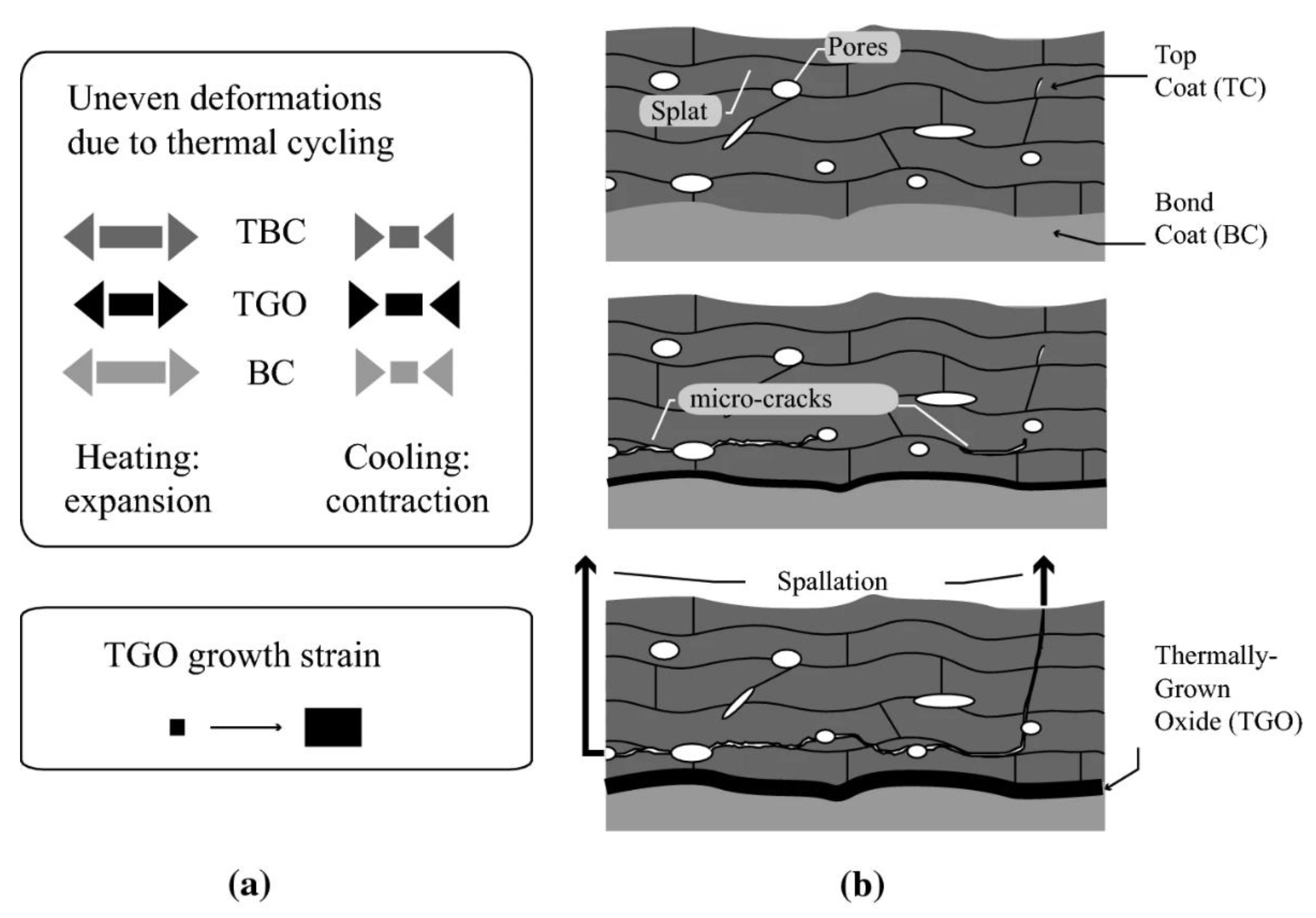
Figure 4. A failure mode illustration of APS deposition technology. Reprinted with permission from [13]. Copyright 2019 Springer Nature. (a) TBC loading conditions; (b) Crack coalescence and TBC failure.
3. Water-Stabilized Plasma Spray
With the increasing demand for large-scale and mass-production coatings, WSP is an ideal choice due to its prospects for extending the lifespan of a TBC coating. Due to its high-power plasma jet, an coating of excellent quality is predicted to result from WSP, which induces an increased powder melting point. As a result, the defects are minimized within the coating [14]. In a study by Ctibor et al., a novel TBC material consisting of strontium zirconate (SrZrO3) was deposited on a stainless steel substrate through WSP. The results demonstrated a satisfactory quality without cracks or disruptions at the interface of SrZrO3 coating and substrate [15]. In addition, a porous coating was observed, and porosity is a needed property for plasma-sprayed coatings. The overall coating exhibited lamellar microstructural properties with low thermal conductivity, allowing more extensive thermal and mechanical performance optimization than an APS deposition technology [15].
The WSP effectively deposits ceramic coatings and extends its usage into other protective coatings. In Figure 5, two different types of splats are distinguished in the coatings—those fully molten into flattened splats and unmolten particles formed in the spherical-like microstructure. A large proportion of pores and cracks were also observed within the microstructures. The morphology of WSP and APS differ because of the contrasting deposition conditions. The former governs by a larger diameter of particles in the feedstock, a higher feed rate, and high-power plasma torch output. Therefore, fatigue behavior can be substantially influenced based on the type of testing conditions. The FeAl-WSP, of similar atomic percent, had better fatigue resistance than APS deposition technology. The reported reason is due to the absence of coating delamination or intrasplat cracking, even when a higher thickness was attributed [16].
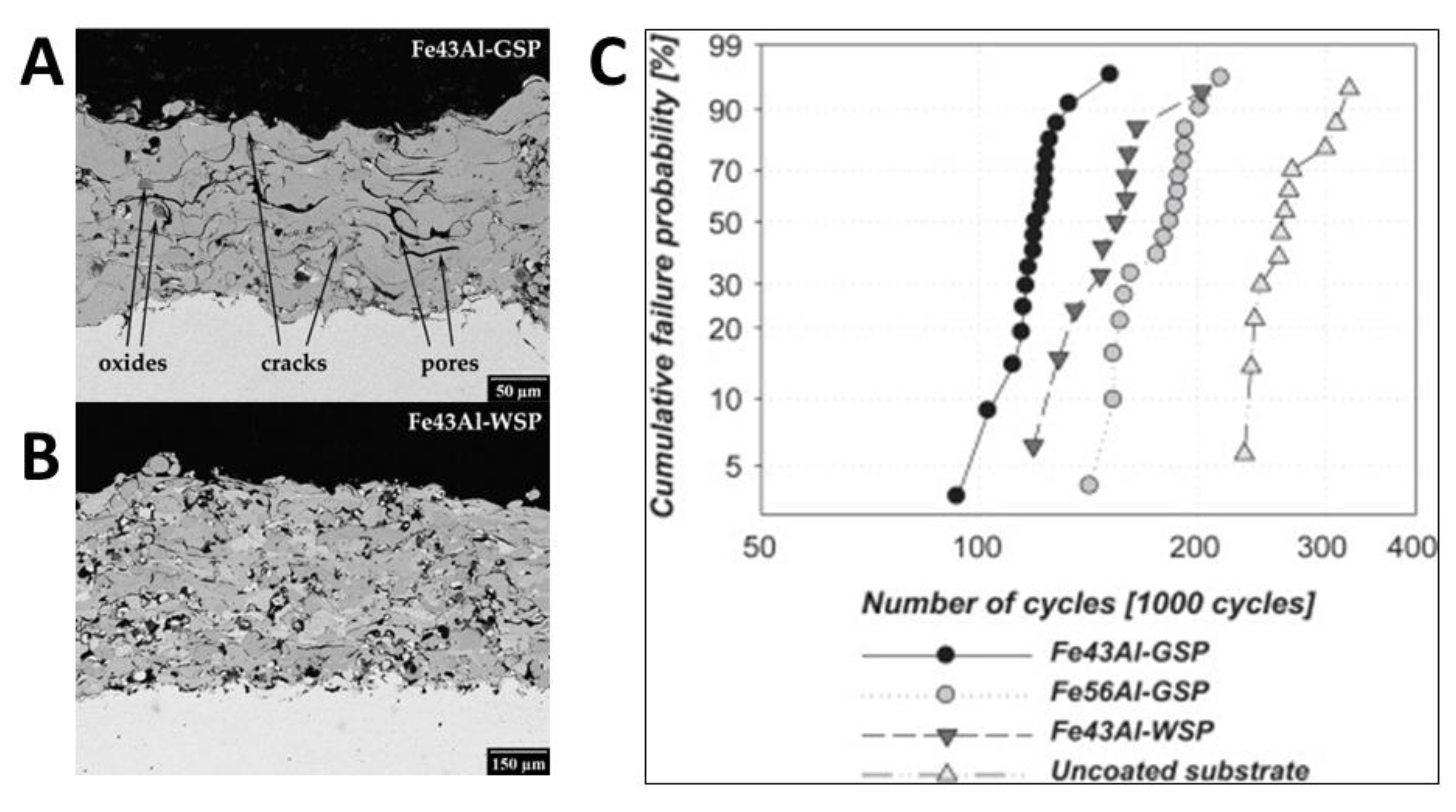
Figure 5. The microstructural view of FeAl intermetallic compound: (A) Fe43Al of gas-stabilized plasma spray, (B) Fe43Al of water-stabilized plasma spray, (C) fatigue test analysis. Reprinted with permission from [16]. Copyright 2010 Elsevier Ltd.
This entry is adapted from the peer-reviewed paper 10.3390/coatings12121916
References
- Łatka, L. Thermal Barrier Coatings Manufactured by Suspension Plasma Spraying—A Review. Adv. Mater. Sci. 2018, 18, 95–117.
- Zhang, X.; Deng, Z.; Li, H.; Mao, J.; Deng, C.; Deng, C.; Niu, S.; Chen, W.; Song, J.; Fan, J.; et al. Al2O3-modified PS-PVD 7YSZ thermal barrier coatings for advanced gas-turbine engines. Npj Mater. Degrad. 2020, 4, 31.
- Clarke, D.R.; Oechsner, M.; Padture, N.P. Thermal-barrier coatings for more efficient gas-turbine engines. MRS Bull. 2012, 37, 891–898.
- Xu, H.; Guo, H.; Gong, S. 16—Thermal barrier coatings. In Developments in High Temperature Corrosion and Protection of Materials; Gao, W., Li, Z., Eds.; Woodhead Publishing: Sawston, UK, 2008; pp. 476–491.
- Odhiambo, J.G.; Li, W.; Zhao, Y.; Li, C. Porosity and Its Significance in Plasma-Sprayed Coatings. Coatings 2019, 9, 460.
- Wei, Z.-Y.; Cai, H.-N.; Zhao, S.-D. Study on spalling mechanism of APS thermal barrier coatings considering surface vertical crack evolution affected by surrounding cracks. Ceram. Int. 2022, 48, 11445–11455.
- Skalka, P.; Slámečka, K.; Pokluda, J.; Čelko, L. Finite element simulation of stresses in a plasma-sprayed thermal barrier coating with a crack at the TGO/bond-coat interface. Surf. Coat. Technol. 2018, 337, 321–334.
- Mahalingam, S.; Yunus, S.M.; Manap, A.; Afandi, N.M.; Zainuddin, R.A.; Kadir, N.F. Crack Propagation and Effect of Mixed Oxides on TGO Growth in Thick La–Gd–YSZ Thermal Barrier Coating. Coatings 2019, 9, 719.
- Wang, L.; Yang, J.; Ni, J.; Liu, C.; Zhong, X.; Shao, F.; Zhao, H.; Tao, S.; Wang, Y. Influence of cracks in APS-TBCs on stress around TGO during thermal cycling: A numerical simulation study. Surf. Coat. Technol. 2016, 285, 98–112.
- Trunova, O.; Beck, T.; Herzog, R.; Steinbrech, R.; Singheiser, L. Damage mechanisms and lifetime behavior of plasma sprayed thermal barrier coating systems for gas turbines—Part I: Experiments. Surf. Coat. Technol. 2008, 202, 5027–5032.
- Nicholls, J.; Deakin, M.; Rickerby, D. A comparison between the erosion behaviour of thermal spray and electron beam physical vapour deposition thermal barrier coatings. Wear 1999, 233–235, 352–361.
- Bolelli, G.; Righi, M.G.; Mughal, M.Z.; Moscatelli, R.; Ligabue, O.; Antolotti, N.; Sebastiani, M.; Lusvarghi, L.; Bemporad, E. Damage progression in thermal barrier coating systems during thermal cycling: A nano-mechanical assessment. Mater. Des. 2019, 166, 107615.
- Krishnasamy, J.; Ponnusami, S.A.; Turteltaub, S.; van der Zwaag, S. Numerical Investigation into the Effect of Splats and Pores on the Thermal Fracture of Air Plasma-Sprayed Thermal Barrier Coatings. J. Therm. Spray Technol. 2019, 28, 1881–1892.
- Ma, G.; Chen, S.; Wang, H. Micro Process and Quality Control of Plasma Spraying; Springer: Singapore, 2022; Volume XII, p. 669.
- Ctibor, P.; Nevrla, B.; Cizek, J.; Lukac, F. Strontium Zirconate TBC Sprayed by a High Feed-Rate Water-Stabilized Plasma Torch. J. Therm. Spray Technol. 2017, 26, 1804–1809.
- Mušálek, R.; Kovářík, O.; Skiba, T.; Haušild, P.; Karlík, M.; Colmenares-Angulo, J. Fatigue properties of Fe–Al intermetallic coatings prepared by plasma spraying. Intermetallics 2010, 18, 1415–1418.
This entry is offline, you can click here to edit this entry!
