Your browser does not fully support modern features. Please upgrade for a smoother experience.
Please note this is an old version of this entry, which may differ significantly from the current revision.
Subjects:
Engineering, Electrical & Electronic
Nondestructive testing (NDT) techniques in conjunction with artificial intelligence approaches have tremendous potential and viability because it is highly possible to improve the detection accuracy which has been proven in various conventional nondestructive testing techniques.
- rail
- nondestructive testing
- combined NDT techniques
1. Introduction
Nondestructive Testing (NDT) can be defined as an evaluation technique based on the integrity of the object to be evaluated. In other words, it provides insurance for the integrity and properties of the object itself. Ideally, NDT techniques obtain information about all the aspects of the object’s defects and, by doing so, evaluate it according to the relevant technical standard [15].
2. NDT Method
2.1. Visual Inspection Methods
The visual inspection method is suitable for detecting defects such as cracks, deformation, and corrosion on the rail surface. The principle of visual inspection is shown in Figure 1.
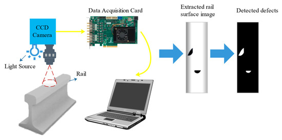
Figure 1. Visual inspection of rail.
It can be seen from Figure 1 that the extracted rail surface image can be obtained from the visual system first. Then the image is converted to grayscale so defects can be detected at high contrast. Automated visual inspection systems can be used to measure the rail head profile and percentage of wear, rail gap, moving sleepers, absence of ballast, base plate condition in the absence of ballast, pincers position, missing bolts, and surface damage [18]. Depending on the inspection type and the required resolution quality, the speed can vary from 1 to 320 km/h [19].
Several factors can affect the accuracy during visual NDT of rails. First, the resolution of the captured video image needs to be higher to provide reliable data for analysis because of the blurring effects during the movement of the camera [20]. Second, the conventional camera cannot obtain the image data about the depth. Third, the environment light changes during the whole day, and the changes in the surrounding light environment significantly impact the capturing image data and influence the stability of defect detection. Numerous studies have been conducted to address the above issues.
2.2. Physical Inspection Methods
2.2.1. Ultrasonic Inspection
Ultrasonic NDT uses ultrasonic waves’ reflection, diffraction, and transmission characteristics to determine whether there are defects inside the workpiece [37]. When inspecting rails with traditional ultrasonic probes, a piezoelectric device transmits an ultrasonic energy beam into the rail. Then a group of transducers detects the transmitted beam’s reflected or scattered energy. Finally, the position and nature of the identified flaws and the overall structural integrity of the rail under examination can be learned from the amplitude of the reflections and the timing of their occurrence [38]. The principle of ultrasonic inspection is shown in Figure 2.
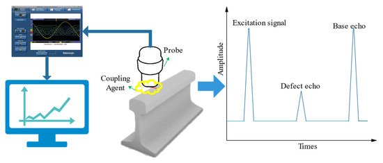
Figure 2. Ultrasonic NDT for rail.
It can be seen from Figure 2 that not only the base echo but also the defect echo are detected after the excitation signal when there is a defect in the detection area. Therefore, we can detect the defects from the characteristics of the wave. Conventional ultrasound technology has been widely used for internal rail defects detection because it has a high penetration capacity. Based on ultrasonic sensors, a real-time photoacoustic imaging system for nondestructive testing of rails can be established [39,40]. The location, direction, and depth of rail defects can be effectively identified by reconstructing the image from the photoacoustic signal. Therefore, it can scan internal rail defects automatically because of its high detection sensitivity. To reduce rail breakage caused by internal rail damage, Network Rail in the UK has developed the handheld rail flaw detector and the rail inspection train based on UT technology, which can effectively detect internal rail core damage [41]. A University of California research team developed ultrasonic inspection equipment with efficient data processing algorithms to accurately detect rail stripping and corrosion defects. The GTC-80 rail flaw detection vehicle, developed by the Chinese Academy of Railway Sciences, was based on ultrasonic detection technology to achieve online flaw detection of high-speed rail [42]. It can effectively detect rail damage with a detection speed of 80 km/h (approx. 22 m/s).
Ultrasonic rail inspection can be performed manually or on special test vehicles. However, conventional ultrasonic has several limitations. Firstly, conventional ultrasonic NDT has a limited speed and cannot be used in long-distance detection because it requires a coupling agent to fill the gap between the probe and the measured surface. The inspection speeds verified in the experiment were only from 40 up to 80 km/h by conventional ultrasonic NDT. In reality, however, inspection speeds can be as low as 15 km/h, particularly when the vehicle must be manually verified [43]. Secondly, it is difficult to detect rail defects with complex shapes or irregular shapes because of the limits of conventional multi-probe ultrasound inspection systems. Thirdly, the defects on the top surface of the rail and the near-surface fatigue damage cannot be effectively detected and assessed. The fatigue crack on the top surface of the rail prevents the ultrasonic wave from being incident into the measured parts, which will have a negative impact on the detection of internal defects in the structure below the fatigue crack. Especially near the gauge angle of the horizontal direction, the defects which have longitudinal extension will have a reflective effect on the ultrasonic wave, preventing the incidence of the sound beam and resulting in the failure to detect the dangerous defects buried below it [44].
New techniques have been developed, such as ultrasonic phased-array inspection, ultrasonic guided wave inspection technology, electromagnetic ultrasound technology, and laser ultrasound technology, to overcome the limitations of conventional ultrasonic NDT techniques.
The ultrasonic phased-array system consists of multiple arrays of independent piezoelectric wafers. The spotlight’s position and orientation are controlled by specific rules and timing sequences, which can effectively detect internal defects of complex shapes with high accuracy [44,45]. Ultrasonic phased-array systems are gradually replacing conventional multi-probe ultrasound inspection systems. The new automated ultrasound inspection system consists of a pair of phased-array probes, and it is capable of performing a large number of tasks [46,47]. Ultrasonic defect detection systems consisting of phased-array probes and field-programmable gate array (FPGA) modules can increase the speed and accuracy of detection [48]. Especially in particular locations such as welds, ultrasonic phased-array inspection has proved more efficient than conventional ultrasonic inspection.
Guided waves are a kind of long-range ultrasonics that can be effective over distances up to 30 m from the sensor array [49]. At semi-infinite or two semi-elastic media surfaces, ultrasound waves are reflected or transmitted due to differences in the material properties of the media, resulting in a shift in the waveform [49,50,51]. Due to different waveforms and different propagation speeds, different waveforms propagate in the medium at their inherent speeds. When ultrasound waves are propagated in a medium with boundaries, such as steel rails, various reflected, transmitted, refracted, and interfacial waves appear as coupled waveforms, thus forming ultrasound-guided waves [52,53].
Compared with traditional ultrasonic inspection technology, ultrasonic guided wave inspection technology uses low-frequency ultrasonic waves, which have the outstanding advantages of long propagation distance and fast speed. British Rail Network Rail has developed the G-Scan rail ultrasound-guided wave inspection device, which uses low-frequency ultrasound-guided waves to detect defects in aluminum thermal welds over long distances [54,55]. Moreover, the 300 kHz pseudo-Rayleigh guided waves have been used for long-distance detection of different defects on rail undersides [56]. However, various factors can significantly attenuate the signal to the extent that the effective distance may only be a few meters in some cases. The wave mode and frequency selected determine the most effective inspection range.
Meanwhile, the entire object cross-section, including transverse rail defects, can be inspected. For instance, based on the guided wave propagation and scattering characteristics at the bottom of the rail, guided waves can be used to detect oblique cracks at the bottom of the rail in the vertical vibration mode [50]. The pulse-echo method can be used to quickly locate defects at a certain distance from the rail head. Prism, which has been developed by Wavesinsolids LLC in the USA, has a maximum inspection speed of 15 km/h, and it has been reported to be capable of detecting large transverse rail head defects [57]. The static tests were conducted on a piece of rail that contained simulated transverse cracks in the rail head that extended below 20% of the total cross-sectional. The University of Pittsburgh developed the rail head damage detection system based on ultrasonic guided wave technology [58]. It used wavelet transform and unsupervised learning algorithms to identify rail damage and maximize the sensitivity of the detection system. The tests have been carried out on rails at an inspection speed of 10 km/h, with damage detection rates between 75% and 100%. Based on guided wave technology, Gurevich developed an ultrasonic guided wave flaw detector AKR1224 [59]. The equipment used 12 antenna array sensors to detect rail defects. Defects such as rail head stripping, rail head injury, and screw hole crack can be detected from multiple angles. It has a high detection rate. Mariani developed the non-contact ultrasonic guided wave rail inspection vehicle for rapid detection of vertical defects using laser excitation and air coupling.
The electromagnetic ultrasound first generates a high-frequency current in the zigzag coil via an external circuit, which induces eddy currents in the opposite direction on the surface of the rail head. At the same time, the eddy currents caused by the strong static magnetic field provided by the magnet cause vibrations in the surrounding masses, resulting in electromagnetic ultrasound surface waves [60]. Electromagnetic ultrasound technology uses the Lorentz force and magnetostriction effects to excite and receive ultrasound waves in conductive specimens. The orientation of the magnetic field, the geometry of the coil, and the physical and electrical properties of the material under investigation strongly influence the ultrasound generated within the sample [41]. Compared to conventional ultrasonic NDT techniques, it has the advantages of high accuracy, no coupling agent required, non-contact measurement, and fast inspection speed as it is an electromagnetic coupling mechanism that generates the ultrasound within the sample skin depth [61]. Several electromagnetic ultrasound NDT vehicles have been developed. For instance, VIGOR Russia has developed the electromagnetic ultrasound NDT vehicle named UD-EMA-RWT-01M, which can provide complete coverage of the rail head, rail waist, and rail bottom at speeds between 0.1 and 1 m/s [62]. Canadian company Tektrend has developed RailPro, an electromagnetic ultrasonic rail flaw detection system for the online verification of many types of rail defects at speeds between 5–9 km/h [63]. Significantly, the defects include transverse fissures, horizontal and vertical head splits, split webs, bolt hole cracking, and RCF damage.
Laser ultrasonic systems operate by first generating ultrasound in a sample using a pulsed laser. When the laser pulse strikes the sample, ultrasonic waves are generated through a thermoelastic process or by ablation. Pulsed lasers can be used to generate all types of ultrasonic waves, including compressional, shear, surface, and plate waves [64]. When ultrasonic waves reach the sample’s surface, the resulting surface displacement can be measured with a laser ultrasonic receiver based on an adaptive interferometer. Laser pulses can produce sound waves with a wavelength of only a few microns, allowing the detection of minor defects within the material. Therefore, it has high accuracy [65]. No coupling agent is required in the testing process, so acoustic-solid coupling does not affect the testing speed. For complex-shaped workpieces, laser ultrasound technology can generate multiple modes of ultrasonic signals in a single excitation process. Therefore, it can be applied to the real-time detection of micro-cracks in rails with high accuracy in harsh environments. Laser ultrasound detection has been validated by detecting rail internal defects of different sizes [65,66]. Meanwhile, the current automated laser ultrasonic rapid rail defect detection device can detect defects on the rail surface as well as horizontal and vertical rail defects in the rail head at speeds of up to 40 km/h [67,68].
In general, ultrasonic inspection detect deep surface-breaking and internal defects relatively well. However, these high-speed systems usually cannot detect defects smaller than 4 mm deep. Such surface defects can shadow critical internal defects and thus give a false picture of the rail’s structural integrity. Ultrasonic inspection can also miss some defects in the rail foot, especially corrosion, as this part of the rail can only be scanned partially. Meanwhile, they also perform relatively poorly when inspecting alumino-thermic welds.
2.2.2. Eddy Current Inspection
Eddy currents testing (ECT) is commonly used to inspect conductive materials for detecting surface and subsurface defects. Typically, eddy current sensors are comprised of one exciting and one sensing coil. The magnetic field near the surface is generated by feeding an alternating current to the exciting coil. Changes in the magnetic field cause eddy currents to be induced just below the surface. The search coil detects changes in the secondary magnetic field generated by the eddy currents in the form of an induced voltage. When a near-surface or surface defect is present, the eddy currents are disturbed, causing fluctuations in the secondary magnetic field, and giving rise to changes in the impedance [69,70].
ECT can detect near-surface or surface damage on the rail head. Thus, it can complement the performance of ultrasonic transducers. The probe coil can obtain the magnetic field changes, thus obtaining defect characteristics on the rail. The principle of eddy current inspection is shown in Figure 3.
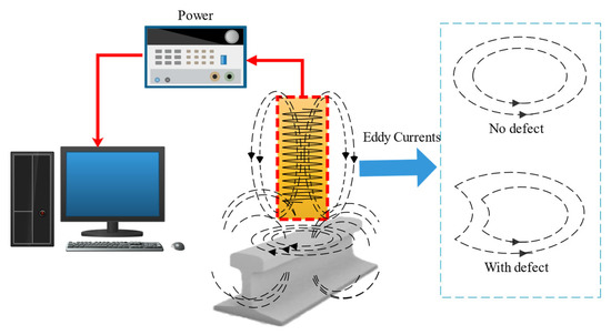
Figure 3. Eddy current inspection for rail.
It can be seen from Figure 3 that the eddy current changes when a defect is detected. The dimensional characteristics of defects can be quantified by the characteristic values of eddy current changes. ECT is non-contact and can be used in high-speed inspection. The inspection speed achieved by the combined ultrasonic/eddy current systems is typically 75 km/h, but higher speeds of up to 100 km/h have been reported [71]. Sperry Corporation in the USA combined ECT and ultrasonic inspection techniques to detect rail surface defects and internal defects. Meanwhile, it can detect cracks in different depths by adjusting the eddy current sensor frequency, coil, and other parameters [72,73]. Furthermore, ECT performs well in special areas such as surface defects on the curved-tip rail of the turnout and surface defects on the inside of the variable-section turnout track. Thomas investigated ECT for the detection of contact fatigue cracks and combined it with ultrasound technology for the defects in rail welds and joints [74]. The German Federal Railways has designed and developed two types of rail inspection equipment using eddy current detection technology, which are vehicle-mounted and hand-pushed [75]. The inspection train, which was vehicle-mounted with eight eddy current probes, four for each rail, can be used at a speed of 50 to 80 km/h to achieve routine inspection of rails. Furthermore, the hand-pushed equipment was equipped with four eddy current probes, which can detect railway turnouts and areas that cannot be reached by trains.
However, ECT has a collective skin effect and only detects the surface and near-surface structural state of conductive materials. In addition, the main issue for the eddy current inspection is that this type of sensor is susceptible to lift-off variations. Thus, the distance between the detection probe and the measured rail surface should be kept fixed (generally within the range of 2 mm) [76]. For that reason, the probe needs to be positioned at a constant distance from the surface of the rail. Particular attention must be given to any lift-off variations that may occur during an inspection. The changes in the lift-off variable could influence the accuracy of the predicted depth.
Pulsed Eddy Current (PEC) is proposed to enhance the penetration of eddy currents. PEC uses a pulsed excitation signal to induce transient eddy currents in the part being measured [77]. The coil induces a time-varying voltage, which is analyzed to detect defects at different depths, characterize properties, and assess the condition of the specimen by analyzing the change in frequency of the transient currents. The technology has the advantages of rich spectrum content for detecting and identifying defects at different depths, fast detection speed, and non-contact detection. Newcastle University in the UK was the first to experiment with this application in the area of rail defects with good results [78].
Furthermore, PEC can integrate with thermal imaging technology based on electromagnetism’s eddy current and Joule heat phenomena. Eddy Current Pulsed Thermography (ECPT) uses infrared thermography to obtain the temperature distribution and conduction of conductive specimens under pulsed eddy current excitation [79]. The length, width, depth, and inclination of rail defects can affect the thermographic data. The principle of ECPT is shown in Figure 4.
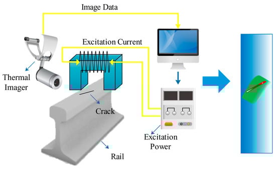
Figure 4. ECPT inspection for rail.
It can be seen from Figure 4 that the thermal imaging of a defect is clearly distinguishable from the surrounding background. Therefore, the size of the defects can be analyzed by image-recognizing techniques. ECPT combines the advantages of pulsed eddy current and infrared thermography. Thus, it can rapidly visualize the rail fatigue cracks. Furthermore, it can concentrate the heat on the defects. Therefore, the temperature difference between the defective and non-defective areas increases, and spatio-temporal characteristics and rich transient information can be obtained. Thus, it can improve the signal-to-noise ratio and detection sensitivity, especially for small defects such as fatigue multi-crack and micro-defect damage on the rail surface [80]. With that, Vrana J. developed the ECPT systems, which can effectively detect cracks in 0.1 mm resolution in depth. Moreover, the longitudinal parallel crack can be detected using ECPT [81]. The Fraunhofer Institute for Nondestructive Testing in Germany has applied ECPT technology to detect rail and wheel surface cracks. They mounted the equipment on the rail test vehicle. The results showed that at low speeds (2 km/h), the device could effectively image rail surface cracks and at a maximum travel speed of 15 km/h (approx. 4 m/s), the device can only detect large rail surface defects [82].
The main factors affecting the ECPT are the excitation coil, the yoke, the temperature rise, and the type of defect. Therefore, the temperature distribution of rail surface defects was investigated through induction thermography simulation and experimental analysis. The results indicated that the eddy current penetration correlated with the temperature rise. Using single-turn coils to detect small cracks on the rail surface by ECPT will easily cause uneven heating. Thus, the improved Helmholtz coil excitation structure was developed to enable uniform heating of the rail surface, eliminating the shortcomings of single-turn coil non-uniform heating in the detection [83]. Meanwhile, the ferrite yoke excitation structure was used for uniform heating and unobstructed visualization of defects on the top surface, facilitating quantitative assessment of defects.
2.2.3. Magnetic Flux Leakage Inspection
Magnetic sensors can detect the leakage field to analyze the rail surface defects. The principle of MFL inspection is shown in Figure 5.
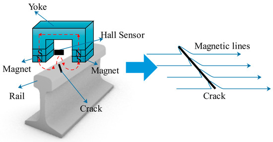
Figure 5. MFL inspection for rail.
It can be seen from Figure 5 that when the magnetic lines encounter defects, the magnetic lines are bent. This is because the magnetic field lines are refracted as they pass through the interface between a ferromagnetic object and air. The leakage field from the defect can be analyzed by Finite Element Simulation, and then the flux density distribution curve can be obtained. The simulation results indicated that the features of the leakage signal could be obtained from the leakage flux density curve [86]. Therefore, it can be used to identify the defect information.
In 1928, Dr. Elmer Sperry successfully developed the world’s first rail flaw detection vehicle based on the principle of magnetic leakage detection under the auspices of the American Railway Union [87]. It could detect surface and near-surface cracks in rails very well but could not detect complex components and deeper defects.
There were several limits for rail MFL inspection. Firstly, the defect’s depth is difficult to identify by permanent magnets or DC electromagnets. Secondly, increasing inspection speed also has a negative impact on MFL. The magnetic flux density in the rail decreases with increasing speed. As a result, the signal becomes insufficient to detect at speeds more than 35 km/h [88]. However, research by new technologies has gradually solved these issues in recent years.
For the first limit, the current research integrates pulse leakage and pulse reluctance technology to detect different depths of rail cracks on the rail surface, achieving better results [89]. Furthermore, MFL inspection equipment by sensor array can obtain more information about the leakage field. Therefore, it can significantly improve the prediction accuracy of defects, especially for the depth of the defects. Meanwhile, the sensor array can form the three-dimensional leakage magnetic field image to describe rail defects [90].
For the second limit, in [91], the authors investigated that hall sensors in MFL systems can improve their performance at higher speeds. Meanwhile, in [86], the authors simulated the leakage magnetic field at high speed to study the dynamic magnetization and velocity effect in the high-speed leakage detection of rail cracks. The research above reduced the speed effect during rail flaw inspection by MFL techniques. In [92], the authors reviewed the nondestructive testing method of metal magnetic memory and established a magneto-mechanical model based on a nonlinear constitutive relation for ferromagnetic materials under a constant weak magnetic field. Theoretical results obtained from the proposed model are more consistent with experimental data, and the proposed magneto-mechanical model applies to various ferromagnetic materials. Meanwhile, in [93,94,95,96] the authors investigated a magnetic shielding strategy and assessed the evaluation of defect depth in ferromagnetic materials via the magnetic flux leakage method with a double Hall sensor.
Near-surface or surface defects like cracks on rail heads are particularly well-detected by MFL sensors. However, internal defects cannot be detected because they are too far from the sensor coils. Therefore, MFL is commonly used as a complementary technique to ultrasonic inspection because it cannot detect internal defects.
2.2.4. Other Physical Inspection Methods
Alternating current field measurement (ACFM) is based on the principle that an alternating current can be induced to flow in a thin skin near the surface of any conductor. The geometry of the component cannot affect the alternating current [97]. Measuring changes in the current on the rail surface enables fast and accurate non-contact detection.
When using ACFM probes, a maximum operating lift-off of 5 mm is possible without suffering a significant loss of signal, in contrast to eddy current sensors, which must be positioned at a close (2 mm) and constant distance from the inspected surface [98]. The signal strength of the eddy current sensor decays with the cube of the lift force. However, the signal strength of the induction sensor decays with the square of the lift force. As a result, the ACFM technique can handle a much higher lift-off [99]. The hand-pushed detection vehicle has been designed based on ACFM technology to detect fatigue damage on the rail surface [100]. It was used to test different sizes of defects on rail surfaces at different speeds, achieving better detection results than conventional methods. A team of researchers at Buckingham University developed a rail vehicle based on the principle of Alternating Current Field Measurement (ACFM). It can detect cracks on rails at speeds of up to 121.5 m/s [101,102]. However, due to vibration in the vertical direction of the equipment during the detection process, the detection accuracy does not meet the specified requirements [96,97]. Meanwhile, the ACFM system has been verified that it can detect cracks smaller than 2 mm in depth [103].
Barkhausen Noise Testing (MBN) is based on the relationship between dynamic magnetization properties and microstructural changes in ferromagnetic materials. During the workpiece’s magnetization by applying an alternating magnetic field, the material is magnetized in the external magnetic field direction [104]. The coil detects the sudden change and stops the noise signal caused by the discontinuous change of magnetic flux in the workpiece. Therefore it can obtain the microstructure and stress information of the material [105]. The principle of MBN inspection is shown in Figure 6.
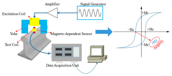
Figure 6. MBN inspection for rail.
It can be seen from Figure 6 that the hysteresis loop changes for the defects and the characteristics of the defects can be analyzed by the variation of the magnetic domain. MBN inspection can assess the microscopic changes in properties such as stress, hardness, and aging. It has the following advantages:
- (1)
-
Barkhausen noise is an essential reflection of the microstructure of ferromagnetic materials. Therefore, it can describe the internal stresses of ferromagnetic materials under restricted conditions such as rail deformation [106].
- (2)
-
Barkhausen noise is an electromagnetic nondestructive testing technique that can be used for non-contact detection of stresses [107].
- (3)
-
According to the MBN generation mechanism, MBN testing techniques can detect not only the magnitude of stresses but also the fatigue life of ferromagnetic materials and microstructures.
Meanwhile, MBN rail stresses are related to temperature changes. Therefore, the effects of temperature changes should be considered in the MBN detection method [108]. The integration of magneto-acoustic emission and MBN techniques for detecting stresses in ferromagnetic materials such as rails has already yielded good results.
Acoustic emission inspection is based on the principle that internal local energy is rapidly released when an object is subjected to a force, resulting in a transient elastic wave [109]. The elastic wave signal will be emitted at the moment of cracking. Collecting and analyzing this elastic wave makes it possible to determine whether there is damage on the rail [110]. The principle of acoustic emission inspection is shown in Figure 7.
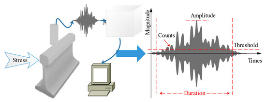
Figure 7. AE inspection for rail.
It can be seen from Figure 7 that the duration, counts, threshold, and amplitude can be calculated from the acoustic wave, and the defects can be quantified by its characteristics. Early applications of acoustic emission were to analyze the stress and strain on rails when trains pass over bridges. It theoretically demonstrated that acoustic emission techniques could detect rail cracks [111]. The wheel-rail simulation has verified that the characteristics of acoustic emission sources in rails can identify different damage stages of the rail. Meanwhile, the acoustic emission inspection method is more accurate in detecting the onset of fatigue crack extension on the rail surface.
Acoustic emission technology is a kind of dynamic detection method for rail cracks. It has the advantages of high sensitivity, and it can monitor dynamic cracks. However, it cannot detect the existing static cracks, and it is easy to be influenced by external noise [112].
This entry is adapted from the peer-reviewed paper 10.3390/coatings12111790
This entry is offline, you can click here to edit this entry!