Knuckle parts have a complex relationship with adjacent vehicle parts, making it difficult to determine the proper fatigue evaluation specification when considering vehicle operation. An accelerated triaxial load case for the knuckle part was derived using a combination of four event modules from the test code developed by the Korea Automotive Technology Institute. The fatigue damage analysis of the front and rear knuckle models was conducted with respect to the accelerated triaxial load case, and the maximum stress was measured at hotspots for the magnitude and orientation of the critical plane. The sensitivity analysis of the knuckle models was conducted for six directions of the unit force, and the proper uniaxial force orientations of the two knuckle models were determined for the maximum stress similarity in the triaxial load case in terms of the magnitude and orientation of the critical plane.
1. Introduction
The knuckle part is the main component that supports all suspension parts, arms, and links, and the hub bearing is inserted in the body position to perform a rotating motion from the driving shaft to the wheel. Therefore, the mechanism between the knuckle and adjacent parts is complicated, and the reliability of the responsible knuckle part is critical for the suspension module and the power transmission line. The effect of the stiffness of the knuckle part has been investigated for a McPherson strut suspension module [
1], and the fatigue analysis of the knuckle part was conducted based on material variability [
2]. In recent studies, the mechanical properties of an Al 6061 alloy composite knuckle were evaluated to verify the feasibility of a novel casting process [
3], and the fatigue life analysis of a knuckle part under different loading conditions and constant/variable amplitudes was investigated [
4]. Because the knuckle is a vital connector in suspension, the noise- or vibration-related problem at the suspension module was refined by modifying the knuckle design specification [
5,
6]. A recent study verified that energy-based instant fatigue damage tracing algorithm led to reliable damage prediction for knuckle part under complicated multi-directional load conditions and that conventional linear critical plane type criterions did not well match with test results [
7]. However, the calculated damage results in this study were calculated using the conventional fatigue criterion (linear critical plane type) because the knuckle part was analyzed for the finite element (FE) model using commercial software. For commercial software, the supported fatigue damage criterion was limited.
The similarity concept of the test procedure can be used to conduct an accelerated mechanical test instead of the original test condition to save time and cost. The feasibility of the accelerated test depends on the judgement criterion, so the selection of the physical criterion should be performed with careful consideration. In the case of the vibration test, the indirect fatigue damage during the test process is critical for deriving accelerated test specifications in the vehicle industry [
8,
9]. Because the accumulated fatigue damage from an excitation is not directly calculated using the measured response acceleration data, the frequency response function between the acceleration and stress at the hotspot was introduced and validated using the uniaxial excitation test [
10]. The mean value of assigned loading sequences was a critical issue in the determination of the accumulated fatigue damage so that recent study was closely investigated the mechanical properties using simple S355J0 steel specimens [
11]. In the case of fatigue damage, a simple criterion for evaluating the fatigue resistance is possible with the maximum stress value at hotspots. Therefore, the similarity concept was used for the target knuckle part by comparing the maximum stress condition at the hotspot. The stress similarity was defined as the similar stress condition for the two cases, the stress value, and the angle of the critical plane, and the maximum stress similarity was satisfied for the similar stress condition at the hotspot for those two values.
A sensitivity analysis was also performed to derive the proper orientation of the uniaxial load case over several candidate unit-force cases. The basic concept of sensitivity analysis is to guide the design modification over several candidate conditions, that is, design parameters, system parameters, or responses of the responsible system [
12,
13,
14]. Because the accelerated fatigue load case is a harsh test procedure for replacing the original load case, many trials and errors may be required to derive a suitable load case, and sensitivity analysis can yield a reasonable solution for minimum trial simulations.
2. Accelerated Triaxial Load Events
A vehicle test was performed to measure the response data from the sedan-type vehicle (2700 cc, Hyundai Motor Company, Seoul, Republic of Korea), and severe distinct events of the test load were adopted at the proving ground (PG) in KATECH. The vehicle test scenario was followed according to the test code developed in KATECH, which is suitable for suspension modules for middle-range vehicles [
19,
20,
21]. The test code was based on the car loading standard (CARLOS), and the CARLOS specification was developed by two institutes (Fraunhofer LBF/Munich, Germany, IABG/Ottobrunn, Germany) and European car manufacturers [
22,
23]. Representative forces applied to the vehicle suspension module are shown in
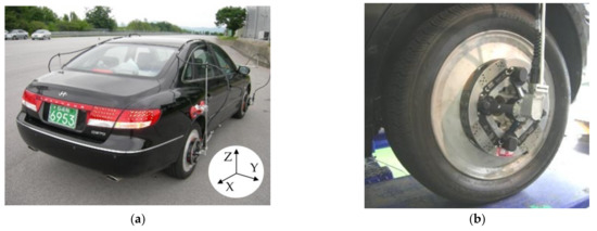
Figure 1. The candidate test tracks were prepared from specific loads applied in KATECH, and the reaction forces at the wheel center were measured using a wheel force transducer (Michigan Scientific Corp., Charlevoix, MI, USA), as depicted in
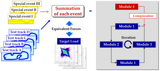
Figure 1. Three regular event modules and one compensation event module were derived from the combination test tracks in the KATECH PG, as shown in
Figure 2. Finally, the specific vehicle test scenarios were determined from the selected four event modules because all event modules were a combination of test tracks in the KATECH PG.
Figure 1. Measurements of wheel force data for target vehicle using wheel force transducer: (a) Test vehicle at PG; (b) Attached wheel force transducer.
Figure 2. Vehicle test procedure for obtaining four event modules from measured wheel force data.
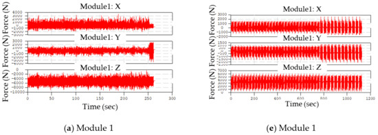
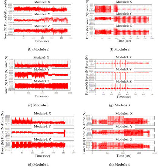
All possible vehicle track tests on the target vehicle were performed, and the four event modules (Figure 3) were derived to evaluate the knuckle part. Because the target knuckle parts were two (the front and rear), the corresponding events were also prepared for two cases: front and rear wheel forces. The four synthesized event modules were computed from the measured wheel forces using the Tecware software (LMS, Leuven, Belgium), as shown in Figure 3.
Figure 3. Computed event modules of target vehicle: (a–d) event modules (#1–#4) for front suspension; (e–h) event modules (#1–#4) for rear suspension.
The four calculated event modules can be used for the accelerated fatigue analysis of suspension module parts so that the synthesized data can be used to assign forces at the wheel center of the knuckle parts.
3. Fatigue Analysis of Knuckle Parts
3.1. Analysis Setup
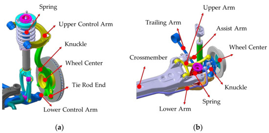
Two knuckles, the front and rear, were considered the target parts for fatigue analysis, and the connecting relationships between adjacent parts were complex. The inserted wheel bearing in the knuckle body connected with the driving wheel, and several arms and links were connected with the knuckle part. The suspension types of the suspension module of the target vehicle are the double-wishbone and multilink, and the connection relationship with the knuckles is shown in Figure 4. A FE model of the two knuckles was established using the commercial software, HyperMesh/Altair, Troy, MI, USA, and a three-dimensional tetra-mesh type was applied to the FE models. The total number of nodes and elements is 14,493, 55,930 for the front knuckle and 38,597, 162,069 for the rear knuckle, respectively. The materials of the two knuckle models were an aluminum alloy, ADC12.
Figure 4. Connection between knuckle parts and adjacent vehicle parts: (a) Front suspension (double-wishbone type); (b) Rear suspension (multilink type).
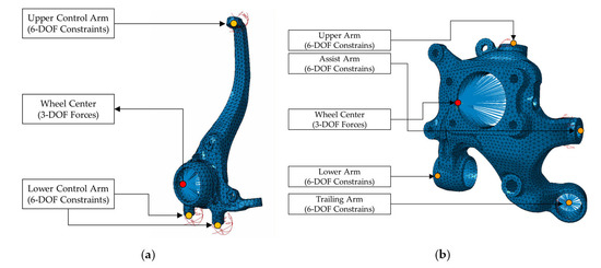
Two options can be applied to clamp them, and the applied force location depends on the clamping conditions. The first option is to clamp all connecting positions with suspension modules, that is, the upper arm, lower arm, and other links, and apply wheel forces on the wheel center. The second is to clamp the wheel center and apply reaction forces on all connecting locations, that is, the upper arm, lower arm, and other links. The accelerated wheel forces were previously measured and processed into four event modules according to the test code in KATECH such that the force input at the wheel center was reliable under the clamping condition with suspension links or arms. In addition, it is challenging to determine the reaction forces at the arms or links in the suspension module, making it difficult to apply the opposite boundary conditions. Therefore, the clamped condition of the adjacent links was chosen as the boundary condition of knuckle part due to the reliable allocation of force information. If the reaction forces at adjacent links can be obtained accurately, it is also possible to apply for the second option by clamping the wheel center position. The applied boundary conditions for the knuckles are shown in Figure 5.
Figure 5. Boundary conditions of FE model of knuckles for triaxial load conditions: (a) Front; (b) Rear.
3.2. Analysis Results for Knuckle Parts
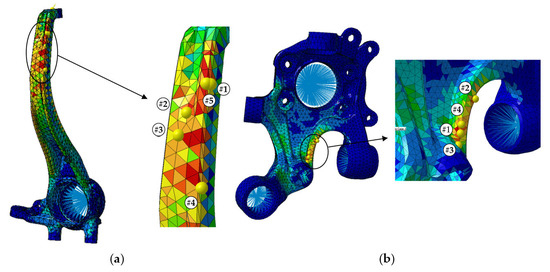
Fatigue analysis of the two knuckle models was conducted using Virtual.Lab (Siemens, Germany) to evaluate the built FE models. The boundary conditions were adopted to clamp all degrees of freedom at the adjacent arms, and the assigned three-dimensional translation forces were applied at the wheel center (Figure 5). A preliminary structural analysis was conducted for the unit-force input at the wheel center, and fatigue analysis was performed using the structural analysis results. The fatigue damage was calculated based on the Goodman criterion supported by LMS FALANCS solver and the S-N curve information provided by the supplier. Because hot spots could be identified by the automatic detector supported in software, the specific locations of first four maximum inverse safety factors were figured out automatically. The stress-concentrated locations are shown in Figure 6.
Figure 6. Stress-concentrated locations over fatigue analysis of knuckle model: (a) Front (b) Rear.
3.3. Uniaxial Load Conditions to Satisfy Severity Similarity
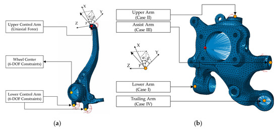
The accelerated uniaxial load conditions were investigated to replace the triaxial load case by satisfying a similar severity, which required similar maximum stress and critical orientation at a nearby location. The two knuckles were simulated using the same FE models, but the boundary conditions differed from those of the triaxial load assignment in Figure 4. If the uniaxial load is applied in the same wheel center, the same stress response will not be expected at the hot points because the two prepared event modules are independent of a directional force. Therefore, the boundary conditions should be changed from the previous triaxial load cases by clamping the wheel force center for the front wheel and clamping several arms with no clamps at the wheel center for the rear knuckle. For the front knuckle, the uniaxial load can be easily applied at the upper arm point owing to the hotspots at nearby locations, as shown in Figure 5. In the case of the rear knuckle, several trials were repeated to select uniaxial load points and other clamping locations. The clamping at the wheel center generated hot points at unexpected locations such that no clamping condition occurred at the wheel center; one arm position was assigned for the uniaxial load, and other adjacent arms were set for clamping locations. Four cases were selected for the modified boundary conditions of the rear knuckle. For example, Case I represents a scenario where the uniaxial load was applied to the lower arm, and the other three arms were constrained as six degrees of freedom. The boundary conditions of the uniaxial load are shown in Figure 7.
Figure 7. Boundary conditions of FE model of knuckles for uniaxial load conditions: (a) Front; (b) Rear.
This entry is adapted from the peer-reviewed paper 10.3390/machines10111097