Your browser does not fully support modern features. Please upgrade for a smoother experience.
Please note this is an old version of this entry, which may differ significantly from the current revision.
Temperature is one of the most important parameters in the combustion processes. Accurate surface temperature can help to gain insight into the combustion characteristics of various solid or liquid fuels, as well as to evaluate the operating status of combustion power facilities such as internal combustion engines and gas turbines. Techniques for surface temperature measurement could be broadly divided into two categories: contact-based thermometry, which is mainly composed of various types of thermocouples and thermistors, as well as non-intrusive thermometry, e.g., radiation thermometry and laser-based techniques.
- surface temperature
- thermocouple
- radiation thermometry
- phosphor thermometry
- application
1. Introduction
Combustion is a fast chemical process in which fuels react rapidly with oxidants and give off heat and light [1]. It is widely applied in power engineering and industry, either for heating purposes or electricity generation by driving a turbine. In addition, for aircrafts or rockets, combustion plays an important role in their propulsion systems, where thrust is generated. To characterize the combustion process, various parameters such as temperature, pressure, velocity, and species concentrations should be accurately measured. In particular, temperature information is virtually indispensable in the study of combustion, since it is closely related to the chemical reaction process, energy conversion efficiency and operation safety. Therefore, temperature measurement in different environments and conditions arouses numerous investigations.
Temperature is the fundamental thermodynamic parameter to weight the ‘hotness’ of matter [2][3]. From the microscopic view, temperature reflects the intensity of the thermal motion of molecules. Temperature is measured by its relationship with some phenomena such as thermal expansion, thermoelectric effects, fluorescence, phosphorescence, radiation, etc. Generally speaking, all the temperature-dependent effects could be used for thermometry. For example, a mercury-filled glass thermometer, one of the most common thermometers, exploits differences between the expansion coefficient of mercury and glass to indicate temperature. Like the mercury thermometer, there are quite a lot of thermometers that utilize medium expansion effect to measure temperatures, e.g., alcohol thermometers. However, their measurement ranges are dependent on the physical properties of the medium, and usually the upper limit of temperature measurement is low. Thus, they are seldom employed in combustion environments in recent years. For a typical combustion system, temperature measurement could be divided into surface temperature measurement and gas temperature measurement, according to different objectives and correspondingly different measurement methods. Apparently, the former refers to the wall temperature of the heating surface, e.g., wall of combustor chamber, turbine blade, or heat exchanger surface, as well as the temperature of liquid or solid fuels in the combustion system. The latter usually refers to the flame temperature, or the temperature of flue gas after combustion. In this entry, researchers only focus on the current state of surface temperature measurement techniques with their principles, developments, and applications. Therefore, some well-known temperature methods such as coherent anti-Stokes Raman spectroscopy (CARS) [4] are not involved in this work.
2. Contact-Based Thermometry
2.1. Thermocouple Method
A thermocouple is a device consisting of two conductors made by dissimilar materials and is applied to measure temperature using the junction of two conductors. It is based on the thermoelectric effect (Seebeck effect), in which temperature difference is converted to electric voltage. This effect was first discovered in 1821; the German physicist Seebeck found that a magnetic needle held near a circuit composed of two dissimilar metals would be deflected when one of the metal junctions was heated. Hence, this phenomenon is called the Seebeck effect, and a simple schematic of this effect is shown in Figure 1. However, at that time, he did not recognize an electric current was generated. Instead, he believed this phenomenon was because of the magnetism induced by temperature difference. With the development of electromagnetism, it was realized that the above effect was due to the induced electric current caused by temperature difference and was named the thermoelectric effect.
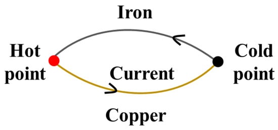
Figure 1. A simple schematic of Seebeck effect.
For a thermocouple, when the two junctions are at different temperatures, electromotive force (EMF) will be generated in the circuit as a result of thermoelectric effect.
Figure 2 illustrates a typical configuration of a thermocouple. The resultant EMF is the function of temperature difference between the two junctions. To achieve temperature measurement, temperature at one of the junctions is usually fixed at a known value, and this temperature is called the reference temperature. Meanwhile, the temperature at the other junction is called the measuring temperature. As a result, resultant EMF is determined only by the measuring temperature. For example, the reference temperature is usually set as 0 °C (the melting point of water). Thus, for thermocouples with the same material and reference temperature, the EMF generated in the circuit is a function of measuring temperature. By calibrating the temperature–dependent EMF curves, thermocouples can be used for temperature measurement. However, in practical applications, especially in industrial utilization, it is not always convenient to maintain the reference temperature at 0 °C. Under these circumstances, reference junction temperature compensation should be taken into account [5]. That is, the measured EMF under these situations should be added to the EMF induced by the temperature difference between the actual reference temperature and 0 °C.
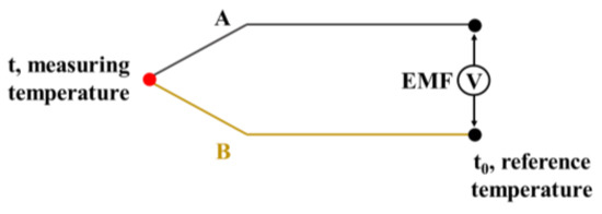
Figure 2. A typical arrangement of thermocouple.
2.2. Thin-Film Thermocouple Methods
When measuring the surface temperature using conventional thermocouples, a hole is usually drilled on the surface in which thermocouples could be fixed. However, this approach would destroy the integrity of the surface. In addition, the bead of a thermocouple would interfere with the flow field around it, which might change the temperature field on the measurement surface. The invention and development of thin-film thermocouples greatly reduced the effects of the above-mentioned problems and made the measurement more flexible. This method has the same principle as conventional thermocouples, while its fabrication procedure is different from the conventional one. Typically, the thin-film thermocouple is fabricated on the measurement surface with the sputter deposit method. Therefore, its thickness is only of a few microns (µm), which is several orders of magnitude thinner than conventional thermocouple wire (cf. Figure 3). This also explains why thin-film thermocouples can reduce disturbances to gas flow near the measurement surface. The thickness of thin-film thermocouples also affects their Seebeck coefficient. Chen et al. [6] found that the Seebeck coefficient of a K-type thin-film thermocouple reached the maximum value with the thickness of 1 µm. A critical factor to achieve surface temperature measurement using thin-film thermocouples is the insulating layer between thermocouples and the base materials, especially as the base material is made of metal. This layer, within a limited thickness, must not only electrically isolate thermocouple elements from the metal base, but also provide the ability to bond thermometry sensors tightly to the measuring surface. Due to the difference between the expansion coefficients of different materials, layer materials were carefully selected, and sometimes multilayer structure was adopted to solve this problem. In addition, to extend the lifetime of thin-film thermocouples under hostile and high-temperature environments, protective film was sometimes utilized. The research of Tian et al. [7] showed that the protective film could avoid the breakdown of thin-film thermocouples under the impact from high-temperature spray.
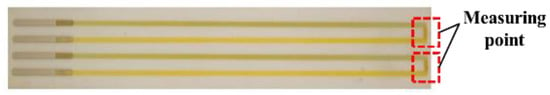
Figure 3. Two thin-film thermocouples fabricated by sputtering onto a ceramic substrate [8].
National Aeronautics and Space Administration (NASA) has been working on developing thin-film thermocouples that could be used on surfaces in harsh environments, such as aero engines and gas turbines, since the 1980s [9][10][11]. They developed a series of thin-film thermocouples with standard materials such as Pt-13% Rh/Pt (R-type) and Pt-10% Rh/Pt (S-type) and applied them to superalloys, ceramics, ceramic composites, and intermetallics. Kreider et al. [12] applied a thin-film thermocouple to three iron-based alloy plates, which represented different internal combustion engine chamber materials. They adopted Al2O3 as the insulating material. In addition, a FeCrAlY alloy layer was coated between the metal base and insulating layer to ensure a high-quality Al2O3 insulating base. The results showed that the insulating layer can survive at over 1100 K in air, with similar accuracy performance as conventional thermocouples. This indicated the feasibility of attaching thin-film thermocouples to almost any iron-based engine alloy. The use of heat treatment processes such as annealing technology are very important to better exert the performance of thin-film thermocouples. Through annealing treatment, the stability of thin-film electrodes can be improved, and thin-film defects can be reduced, thereby improving the performance of thin-film thermocouples. For different types of thermocouples, it is necessary to select proper annealing temperature, duration, and atmospheres [13][14].
3. Non-Intrusive Thermometry
There is a great demand for non-intrusive surface thermometry due to the requirements of high spatial and temporal resolution, remote probing, and non-interference of combustion during the measuring process. According to different principles, these techniques can be classified as (1) radiation thermometry, which is based on thermal radiation; (2) laser-induced phosphorescence (LIP) and the temperature-sensitive paint (TSP) method, which are based on the temperature-dependent property of materials after light excitation; (3) thermochromic liquid crystal (TLC) thermography, which is based on temperature dependence of the color of reflected light from liquid crystals; and (4) the temperature-indicating paint method, which is based on coating color change with varied temperature.
3.1. Radiation Thermometry
Radiation thermometry, also known as pyrometry, is a non-intrusive method which measures surface temperature through thermal radiation emitted from the target surface, since the amount of thermal energy in the form of radiation and its wavelength are functions of temperature. To receive a radiation signal emitted from a target surface, a detector is needed in the measurement system. Generally speaking, a device receiving and interpreting a radiation signal to measure temperature based on radiation thermometry is called a pyrometer. To be more specific, a pyrometer usually refers to the device that records temperature information of a single point, and for a temperature field, it is typically known as thermography [15]. A long time ago, experienced workers determined forging temperatures by observing the color of steel. This can be regarded as a rough surface temperature measurement using radiation thermometry, where our eyes and brain constituted a nominal pyrometer. With the discovery of the photoelectric effect and the development of optoelectronic devices, optical detectors became common in scientific research and industrial applications, which led to great progress in radiation thermometry. Compared with the thermocouple method, radiation thermometry has several unique advantages. For example, it can obtain a temperature field with a fast response, has zero interference to the flow and temperature field, can be utilized in harsh environments, and one of the most important, it has a wider dynamic range than other contact or non-contact techniques. As a result, radiation thermometry has become one of the most commonly used techniques.
3.2. Laser-Induced Phosphorescence
With the development of laser diagnostics, advanced laser techniques such as CARS [16], Raman scattering [17], Rayleigh scattering [18], and LIF [19] are widely used in combustion process. However, most of the above techniques are aimed at measuring the temperature of flames or flue gas. For surface temperature monitoring in industrial operation, such as combustor walls, or temperature of the surface where chemical reactions are going on, such as the surface of a propellant, utilization of the above-mentioned laser techniques is still very limited. A laser diagnostic technique suitable for surface temperature measurement in high-temperature environments is called laser-induced phosphorescence (LIP) or named phosphor thermometry. This technique is based on a type of special material which would emit light after illuminating, and lifetime or intensity of the light is a function of temperature. These materials are known as thermographic phosphors (TP), and the light they emit is called phosphorescence.
Research on the temperature dependence of phosphorescence might date back to the 1930s [20], but this research did not arouse a growing interest in this technique until the second half of the twentieth century. Thureau is believed to be the first man to discuss the temperature dependence of phosphorescence from the view of the spectral distribution [21]. He also employed the ratio of spectral intensities for phosphor thermometry. Until the 1980s, the ratio method was the only phosphor thermometry method used outside the laboratory. Leroux was the first researcher who applied the temporal characteristics of phosphorescence to measure temperature [22]. This was also the precursor of lifetime thermometry. To date, the ratio method and the lifetime method are the most common phosphor thermometry methods. Almost all thermographic phosphors can be used by these two methods, but each kind of phosphor has different sensitivity in different methods. For example, YAG:Dy is more sensitive in the lifetime method, while it is less sensitive in the ratio method. As for ZnO:Zn and ZnO:Ga, they have high sensitivity in the ratio method [23]. In addition, the sensitivity of phosphor materials in each method varies with the temperature measurement range. When using the lifetime method, YAG:Dy is more sensitive at high temperature, i.e., over 800 °C [24].
Due to great interest in laser-induced phosphorescence, several review papers emerged. In 1997, Allison and Gillies [25] published a review of phosphor thermometry. In this article, the history and development of temperature measurement based on laser-induced phosphorescence were introduced, and they also summarized the phosphor materials that had been used, as well as their temperature measurement ranges and application scenarios. Today, this review is still a valuable reference for researchers. Currently, with the increasing demand for non-contact and high-precision temperature measurement tools, the laser-induced phosphorescence technique has been widely studied and exploited. In the past 20 years, many studies on the temperature measurement characteristics of various phosphor materials and review articles have emerged [23][26][27][28].
3.3. Other Non-Intrusive Thermometry
3.3.1. Liquid Crystal Thermography
Thermochromic liquid crystals [29] are used in surface temperature measurement because their optical properties are temperature dependent. With the irradiation of light, the color (wavelength) of the reflected light depends on the crystal temperature. This is because the structure of liquid crystal molecules is optical anisotropy. When thermochromic liquid crystals are applied to the measured surface, the temperature change from the measured surface causes the change in the molecular layer spacing of liquid crystals, thus the frequency of the reflected light changes and behaves as a change in color. Using imaging detectors, for example, a CCD camera, the surface temperature distribution of a target object can be determined. However, a significant shortcoming of liquid crystal thermography is that it has a very low upper limit of temperature measurement. Regarding different liquid crystal materials, the temperature measurement ranges are also different, but generally not more than 400 K. As a result, they are seldom used in the hot environment of a combustion system. Nevertheless, because it is economical and capable of 2D measurement, this method is often used to measure the surface temperature of turbine blades with a cooling system, e.g., film cooling [30][31][32][33][34][35]. In these cases, the heat transfer coefficient is derived from the measured wall temperature to assess the cooling efficiency.
3.3.2. Temperature-Sensitive Paint
Temperature-sensitive paint (TSP) [36][37] is very similar to thermographic phosphors (TP). The temperature measurement using TSP is also based on the temperature-dependent non-radiation process of luminescent materials, whose luminescence intensity and lifetime decrease with increasing temperature as a consequence. To measure the surface temperature, TSP is applied to the target surface. Luminescence is emitted from the coating under excitation by an incident illumination light (e.g., LED lamp or laser) and the signal is received by a detector. Different from thermographic phosphors, TSP is generally composed of organic dye molecules and a polymer binder, while TP is composed of rare-earth or transition metals and a ceramic host and is applied in powder or crystal form. The temperature-sensitive paint technique originated almost at the same time as LIP and was originally developed for aerodynamic testing, including surface temperature measurements and heat flux calculations [38]. Like LIP, it is easy to obtain 2D temperature distribution using the temperature-sensitive paint technique. A comprehensive introduction of TSP was given by Liu et al. [39] about its principles, data acquisition, analysis procedures, and applications. A big limitation of TSP utilization in combustion systems is that its upper limit of temperature measurement is very low, i.e., typically under 380 K [26]. This means that, like liquid crystal thermography, it can only be used to measure the temperature of a surface with a low temperature (e.g., surface with cooling system) in combustion environments [40]. The implementation of temperature-sensitive paint technique and phosphor thermometry is similar. However, phosphor thermometry has a much higher upper limit of temperature measurement range. As a result, it is recommended to use phosphor thermometry in high-temperature environments and TSP for low-temperature environments.
This entry is adapted from the peer-reviewed paper 10.3390/pr10122528
References
- Turns, S.R. Introduction to Combustion; McGraw-Hill Companies: New York, NY, USA, 1996; Volume 287.
- Michalski, L.; Eckersdorf, K.; Kucharski, J.; McGhee, J. Temperature Scales and Classification of Thermometers. In Temperature Measurement; John Wiley & Sons Ltd.: Chichester, West Sussex, England, 2001; pp. 1–18.
- McGee, T.D. Principles and Methods of Temperature Measurement; Wiley: New York, NY, USA, 1988.
- Druet, S.A.; Taran, J.P.E. CARS spectroscopy. Prog. Quantum. Electron. 1981, 7, 1–72.
- Pollock, D.D. Thermocouples: Theory and Properties; Routledge: London, UK, 1991.
- Chen, Y.Z.; Jiang, H.C.; Zhang, W.L.; Liu, X.Z.; Jiang, S.W. Film Thickness Influences on The Thermoelectric Properties of NiCr/NiSi Thin Film Thermocouples. Mod. Phys. Lett. B 2013, 27, 1350103.
- Tian, B.; Zhang, Z.; Shi, P.; Zheng, C.; Yu, Q.; Jing, W.; Jiang, Z. Tungsten-rhenium thin film thermocouples for SiC-based ceramic matrix composites. Rev. Sci. Instrum. 2017, 88, 015007.
- Tougas, I.M.; Amani, M.; Gregory, O.J. Metallic and Ceramic Thin Film Thermocouples for Gas Turbine Engines. Sensors 2013, 13, 15324–15347.
- Holanda, R. Development of thin film thermocouples on ceramic materials for advanced propulsion system applications. In Proceedings of the Conference for Preparation for Temperature: Its Measurement and Control in Science and Industry, Toronto, ON, Canada, 28 April–2 May 1992.
- Martin, L.C.; Holanda, R. Applications of thin-film thermocouples for surface temperature measurement. In Proceedings of the SPIE’s 1994 International Symposium on Optics, Imaging, and Instrumentation, San Diego, CA, USA, 24 July 1994; pp. 65–76.
- Wrbanek, J.; Fralick, G.; Farmer, S.; Sayir, A.; Blaha, C.; Gonzalez, J. Development of thin film ceramic thermocouples for high temperature environments. In Proceedings of the 40th AIAA/ASME/SAE/ASEE Joint Propulsion Conference and Exhibit, Fort Lauderdale, FL, USA, 11–14 July 2004; p. 3549.
- Kreider, K.G. Thin film thermocouples for internal combustion engines. J. Vac. Sci. Technol. A 1986, 4, 2618–2623.
- Zhao, X.; Wang, Y.; Chen, Y.; Jiang, H.; Zhang, W. Enhanced thermoelectric property and stability of NiCr–NiSi thin film thermocouple on superalloy substrate. Rare Metals 2017, 36, 512–516.
- Zhao, X.; Liang, X.; Jiang, S.; Zhang, W.; Jiang, H. Microstructure evolution and thermoelectric property of Pt-PtRh thin film thermocouples. Crystals 2017, 7, 96.
- Glückert, U.L.; Schmidt, R. Pyrometry and Thermography. In Optical Measurements: Techniques and Applications; Mayinger, F., Feldmann, O., Eds.; Springer: Berlin/Heidelberg, Germany, 2001; pp. 271–300.
- Cutler, A.D.; Gallo, E.C.; Cantu, L.M.; Rockwell, R.D.; Goyne, C.P. Coherent anti-Stokes Raman spectroscopy of a premixed ethylene–air flame in a dual-mode scramjet. Combust. Flame 2018, 189, 92–105.
- Raffius, T.; Schulz, C.; Ottenwälder, T.; Grünefeld, G.; Koß, H.-J.; Brands, T.; Pischinger, S. Flame-temperature, light-attenuation, and CO measurements by spontaneous Raman scattering in non-sooting diesel-like jets. Combust. Flame 2017, 176, 104–116.
- Hoffman, D.; Münch, K.-U.; Leipertz, A. Two-dimensional temperature determination in sooting flames by filtered Rayleigh scattering. Opt. Lett. 1996, 21, 525–527.
- Meier, U.E.; Wolff-Gaßmann, D.; Stricker, W. LIF imaging and 2D temperature mapping in a model combustor at elevated pressure. Aerosp. Sci. Technol. 2000, 4, 403–414.
- Allison, S.W. A brief history of phosphor thermometry. Meas. Sci. Technol. 2019, 30, 072001.
- Thureau, P. Etude d’und methode de mesure des temperatures utilisant las sensibilite thermique des couleurs de fluorescence. Doctoral Thesis, University of Paris, Paris, France, 1955.
- Leroux, J.-P. Étude sur la détermination des températures de surfaces (de 0 à 400° C), par l’intermédiaire des émissions de minces revêtements photoluminescents: Par Jean-Pierre Leroux; Service de documentation et d’information technique de l’aéronautique (Impr. du SDIT); 1962.
- Aldén, M.; Omrane, A.; Richter, M.; Särner, G. Thermographic phosphors for thermometry: A survey of combustion applications. Prog. Energy Combust. Sci. 2011, 37, 422–461.
- Allison, S.; Beshears, D.; Cates, M.; Scudiere, M.; Shaw, D.; Ellis, A. Luminescence of YAG: Dy and YAG: Dy, Er crystals to 1700° C. Meas. Sci. Technol. 2020, 31, 044001.
- Allison, S.; Gillies, G. Remote thermometry with thermographic phosphors: Instrumentation and applications. Rev. Sci. Instrum. 1997, 68, 2615–2650.
- Brübach, J.; Pflitsch, C.; Dreizler, A.; Atakan, B. On surface temperature measurements with thermographic phosphors: A review. Prog. Energy Combust. Sci. 2013, 39, 37–60.
- Khalid, A.H.; Kontis, K. Thermographic phosphors for high temperature measurements: Principles, current state of the art and recent applications. Sensors 2008, 8, 5673–5744.
- Chambers, M.; Clarke, D. Doped oxides for high-temperature luminescence and lifetime thermometry. Annu. Rev. Mater. Sci. 2009, 39, 325–359.
- Sage, I. Thermochromic liquid crystals. Liq. Cryst. 2011, 38, 1551–1561.
- Ireland, P.T.; Neely, A.J.; Gillespie, D.R.; Robertson, A.J. Turbulent heat transfer measurements using liquid crystals. Int. J. Heat Fluid Flow 1999, 20, 355–367.
- Ekkad, S.V.; Han, J.-C. A transient liquid crystal thermography technique for gas turbine heat transfer measurements. Meas. Sci. Technol. 2000, 11, 957.
- Okamura, T.; Koga, A.; Itoh, S.; Kawagishi, H. Evaluation of 1700C Class Turbine Blades in Hydrogen Fueled Combustion Turbine System. In Turbo Expo: Power for Land, Sea, and Air; American Society of Mechanical Engineers: New York, NY, USA, 2000; p. V001T003A100.
- Poser, R.; Von Wolfersdorf, J. Liquid crystal thermography for transient heat transfer measurements in complex internal cooling systems. In Proceedings of the TURBINE-09, International Symposium on Heat Transfer in Gas Turbine Systems, Antalya, Turkey, 9–14 August 2009.
- Wang, C. Heat Transfer Investigations by Liquid Crystal Thermography in Gas Turbine Related Applications. Ph.D. Thesis, Lund University, Lund, Sweden, 2014.
- Ekkad, S.V.; Singh, P. Liquid Crystal Thermography in Gas Turbine Heat Transfer: A Review on Measurement Techniques and Recent Investigations. Crystals 2021, 11, 1332.
- Fey, U.; Engler, R.H.; Egami, Y.; Iijima, Y.; Asai, K.; Jansen, U.; Quest, J. Transition detection by temperature sensitive paint at cryogenic temperatures in the European Transonic Wind tunnel (ETW). In Proceedings of the 20th International Congress on Instrumentation in Aerospace Simulation Facilities, ICIASF ‘03, Göttingen, Germany, 25–29 August 2003; pp. 77–88.
- Morris, M.; Donovan, J. Application of pressure-and temperature-sensitive paints to high-speed flows. In Proceedings of the Fluid Dynamics Conference, Colorado, CO, USA, 20–23 June 1994; p. 2231.
- Liu, T.; Campbell, B.T.; Burns, S.P.; Sullivan, J.P. Temperature-and pressure-sensitive luminescent paints in aerodynamics. Appl. Mech. Rev. 1997, 50, 227–246.
- Liu, T.; Sullivan, J.P.; Asai, K.; Klein, C.; Egami, Y. Pressure and Temperature Sensitive Paints; Springer: Berlin/Heidelberg, Germany, 2005; Volume 1.
- Navarra, K.R.; Rabe, D.C.; Fonov, S.D.; Goss, L.P.; Hah, C. The application of pressure-and temperature-sensitive paints to an advanced compressor. J. Turbomach. 2001, 123, 823–829.
This entry is offline, you can click here to edit this entry!