Your browser does not fully support modern features. Please upgrade for a smoother experience.
Please note this is an old version of this entry, which may differ significantly from the current revision.
Subjects:
Engineering, Electrical & Electronic
The use of power electronic inverters leads to the dissociation of sources and loads and lowering the power system inertia. Under power imbalance, this drop causes an elevated rate of change in frequency and frequency divergences, which has a notable impact on the system’s frequency stability. As a result, enhanced control techniques for grid-tied electronic converters are required to secure the power system’s stability and support. The virtual-synchronous generator (VSG) control is used to mimic the dynamics of a rotating synchronous generator and improve the power system’s stability.
- renewable energy sources
- virtual inertia
- virtual-synchronous machine
1. Introduction
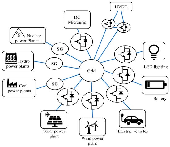
The proportion of renewable energy sources (RES) to power generation has expanded dramatically in recent years, as evidenced by strict environmental regulations, limited fossil fuel accessibility, and the need to meet the rising worldwide power demand. In 2021, global renewable energy capacity increased to about 3146 GW [1], where solar photovoltaics (PV) and wind power accounted for 90% of the new renewable capacity [1]. The unpredictability and uncertainty of RES, such as solar and wind energy, may be a substantial concern to the operation of power systems [2,3]. Aside from their intermittency, they are integrated via power conditioning circuits that detach them from the power grid [4,5]. Using power electronic converters, RES and loads are incorporated into the grid in a future power system, as depicted in Figure 1 [6]. Consequently, when conventional generators are changed with renewable energy sources, the effective inertia of the electrical grid is reduced. When a large quantity of power electronic inverters is used to restore a classic synchronous generator (SG), stability, efficiency, and quality are all improved. Power management along with different sources, on the other hand, is a significant problem in system design and monitoring. Furthermore, integrating RES into the grid on a large scale causes frequency stability concerns [4,7,8]. This is one of the most significant disadvantages of incorporating a significant number of non-synchronous generators into the grid [4,6,9]. The use of power electronic inverters allows sources and loads to be decoupled, resulting in a decline in power network inertia. Under a power imbalance, this drop leads to a rapid shift in frequency and frequency deviations, which also significantly influences the system’s frequency stability [6,9].
Low inertia of the system is linked to a quicker rate of change of frequency (ROCOF) and a higher frequency divergence over a short duration of time [4,11]. The ROCOF is a metric for how rapidly the frequency varies after an unexpected generation–load imbalance. The ROCOF and frequency nadir in the power network are affected when inertia decreases [12]. The ROCOF is the initial slope of the system frequency with time [13]. In a combined system of an SG and RES-based power generation, the frequency change is large, where the RES has no contribution to the system inertia, as can be seen from Figure 2 [6,14]. The producing station may trip if the frequency deviation rises over a specific level, increasing the ROCOF, and finally causing a system chain breakdown [14,15].
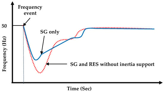
Figure 2. Effect of inertia on frequency [6].
Challenges that come with changes to new power systems are as follows:
-
Traditional power electronics control approaches of dc–ac converters have quick dynamics. However, the synchronous machine (SM) has slow dynamics and significant inertia. At a substantial distributed energy resources (DER) penetration, the grid’s equivalent rotational inertia will greatly decrease. The frequency stability will suffer as a result of this [5].
-
The intermittent power supplied by DERs will be quickly provided to the grid using the fast-response feature of dc–ac converters. Instability in frequency, angle, and voltage will result from these interactions [16]. Similarly, large-size dc microgrids and parallel inverters are challenging to explore, particularly when the DERs and DC-ACconverters have comparable dynamics. DERs, on the other hand, are normally controlled by maximum power point tracking (MPPT) and hence are not dispatchable. As a result, these DC-ACconverters are unable to offer sufficient up-reserve to sustain grid frequency [16,17].
To overpower the challenges caused by grid-connected renewable power generation, virtual inertia (VI) is being developed and intensively explored in traditional inverters. VI uses pulse width modulation (PWM) to mathematically simulate the inertia response of a typical synchronous machine (SM) [10]. The concept of a VI-based inverter is shown in Figure 3, where, to emulate the inertia of a traditional power system, a mix of control algorithms, RESs, energy storage system (ESSs), and power electronics is used.
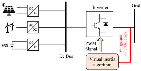
Figure 3. Concept of virtual inertia [18].
2. Current Virtual Inertia Topologies
The ROCOF in a power system network grows as the system inertia decreases, resulting in a bigger fluctuation in the frequency of the system. As new RESs are incorporated into the power system, the system will require greater inertia [11]. In 2007, Beck and Hesse presented the virtual-synchronous machine (VSM) technique [19], which uses power electronics to mimic some of the properties of synchronous generation and provides power system assistance. The VSM control approach has so far been established to regulate power converters to mimic the inertia and other features of the synchronous machine, in light of the growth in renewable production and the resulting reduction in power system inertia [20]. VSM can emulate the inertia of a conventional power network by an integrated approach of control algorithms, power electronics, RES, and energy storage devices [10,21,22]. Although the principle of modeling virtual inertia is similar for various topologies, the execution of each topological model is different. Some topologies use mathematical equations to emulate synchronous machine behavior, whereas a few topologies utilize swing equations to simulate the synchronous generator behavior [23]. Distributed generation (DG) units react to utility grid system frequency variations in a few topologies. This section covers a number of prominent VSM topologies. In the literature, many key topologies of VSM have been proposed, as shown in Figure 4 [6,23,24,25].
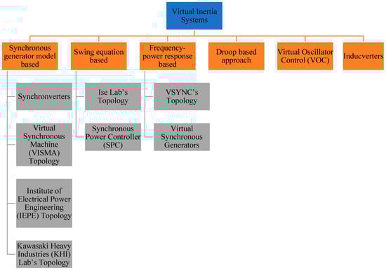
Figure 4. Topologies of VSM.
2.1. Topology Based on Synchronous Generator Model
2.1.1. Synchronverters
Synchronverters perform as an equivalent to a combination of an SG and a small-capacitor bank. Synchronverters control inverter-based DG units as SGs, which, from the grid’s perspective, depict the same dynamics. Synchronverters may be used as grid-forming units without making substantial modifications to their operating structure and are particularly well-suitable for inertia imitation from DGs that are not linked to the grid [26,27]. A frequency droop control algorithm regulates the inverter output power since the frequency derivative is not necessary when using this topology and there is less noise in the system. Furthermore, the moment of inertia and the damping factor may need to change to satisfy certain needs [6]. The overall schematic of the synchronverters is shown in Figure 5.
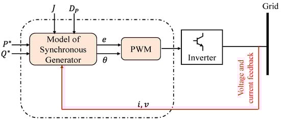
Figure 5. Synchronverter topology overall schematic showing the operating principle [18].
A synchronverter is made up of two parts: a power component, which is similar to the typical power electronic converter shown in Figure 6, and an electronic part, shown in Figure 7, which includes the sensing, protection, and control circuits, where Dp is a damping factor, Te and Tm are the electromagnetic and mechanical torques, and J is the moment of inertia [27].
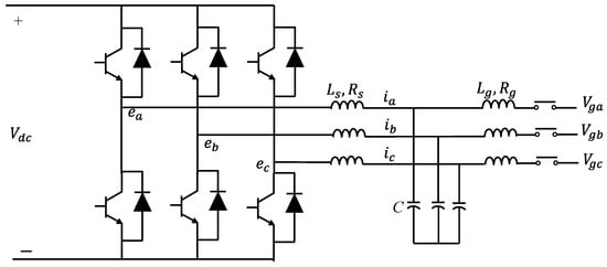
Figure 6. Power stage component of a synchronverter [26].
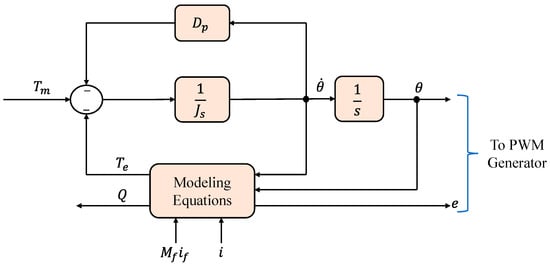
Figure 7. The components of a synchronverter: controller [26].
The synchronverter uses the following equations to model SG behavior, as expressed in [6,18]:
where, Mf represents the size of the mutual inductance between the stator coil and the field coil, if represents the field excitation current, θ represents the angle between one of the phases of the stator winding and the rotor axis, e represents the no-load voltage generated, and Q represents the reactive power produced [18].
A three-phase cylindrical-rotor synchronous machine’s mathematical model is at the heart of the controller of a three-phase synchronverter, as illustrated in Figure 7. The back electromotive force, e, estimated using the mathematical model, is sent into a PWM generating block, which generates PWM pulses to operate the power semiconductors, as shown in Figure 6. The currents that flow out of the power stage’s inductors are counted as the stator current i and return into the mathematical model representation [6,23,26,27]. The synchronverter’s power part is the circuit to the left of the three capacitors, along with the capacitors. If we ignore the ripple, this section of the circuit will operate as an SG with the identical capacitors linked in parallel. Although the Lg inductors are not part of the synchronverter, they are important for synchronization and power regulation. It is essential to include energy storage on the side of the dc bus because the power consumption from the dc bus reflects the power received from the fictitious prime mover and the inertia of the spinning component of the hypothetical SG. The latter component of electricity may arrive in large bursts, proportionate to the grid frequency’s derivative [27]. The synchronverter can reproduce the precise dynamics of an SG, yet the intricacy of the underlying differential equations might lead to numerical instabilities. Additionally, a voltage-source technique may need additional protection mechanisms for safe operation since it lacks inherent safety against powerful grid transients. This might be performed without making significant modifications to the operation’s structure [18].
2.1.2. Kawasaki Heavy Industries (KHI)
Instead of employing a complete dynamic model representation of the SG, the KHI topology implements an analogous model of a governor and automatic voltage regulator (AVR) in a discrete controller to produce the virtual machine’s voltage amplitude and phase reference. These references are employed to generate reference currents using the algebraic phasor representation approach for a synchronous generator, as shown in Figure 8 [18,28,29].
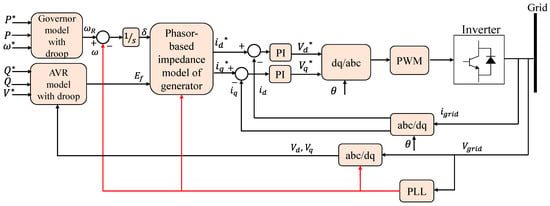
Figure 8. Simple structure of KHI topology [29].
2.1.3. VISMA and IEPE Topologies
The virtual synchronous machine (VISMA) and Institute of Electrical Power Engineering (IEPE) approaches are two more topologies and techniques that have been introduced in various research works [23,30]. For all topologies, the basic principle of simulating an inertia response is the same. In the research effort of [30], the VISMA approach simulates the SG using d−q based architecture. When this architectural design is implemented using a digital control unit of a power converter, the dynamics of a synchronous generator are replicated. However, it has been suggested in the literature that the VISMA approach is unstable due to the use of numerical data. Using a three-phase model, a strategy is created to boost the strength. For asymmetrical loads and abrupt fluctuations in the utility grid, this novel approach is quite effective.
The IEPE topology is a topology that is similar to VISMA, but the main distinction is that IEPE uses the output current of a DG to provide a reference voltage for virtual machines. In the grid-linked mode of IEPE, dealing with transient currents during the synchronization phase is difficult. The IEPE approach, on the other hand, is best-suited for islanded mode [31].
2.2. A Swing Equation-Based Topology
2.2.1. Ise Lab’s Topology
This architecture resolves the power- and frequency-based swing equation in each control step to simulate inertia rather than needing a fully detailed description of the synchronous generator [18,32]. Figure 9 depicts a simplified example of this topology. From the common connection point, the frequency and power measuring equipment collects the voltage and determines the output current of the inverter. It makes an estimate of the utility grid frequency and the inverter’s active output power. The control algorithm unit receives prime mover input power as well as two computed values [23,32,33]. The control technique may be implemented without the need of a frequency derivative, much like a synchronverter. This is very beneficial since frequency derivatives are established to add disturbance into the system, making it challenging to control. This topology may also be utilized to run DG as grid-forming systems. However, there are still issues with numerical instability, which when combined with incorrect setting of the parameters J and Dp, can cause oscillatory behavior of the system [18,33].
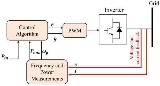
Figure 9. Overall diagram of Ise Lab’s architecture [18].
A SG’s typical swing equation is:
where, Pin and Pout are the input and output powers (W), J is the moment of inertia (Kg·m2), ωm is the virtual angular frequency (rad/s), Dp is the damping factor (Kg·m2/s), and ωg is the reference value of the angular frequency (rad/s) [18,33]. The input power, Pin, is calculated using the governor model, as illustrated in Figure 10, where, P0 is the DG unit’s continuous power reference. With gain K and a time constant Td, the governor is characterized as a lag element of the first order. However, as a result of the governor model’s delay, ROCOF is increased, which raises frequency nadirs [18].
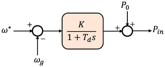
Figure 10. Ise Lab’s topology: the governor model [18].
2.2.2. Synchronous Power Controller (SPC)
The SPC, as presented in Figure 11, is another common topology for implementing virtual inertia. The control algorithm’s general structure is similar to that presented in the Ise lab’s architecture, nonetheless, the converter is not operated as a voltage- or current-controlled system; rather, with an inner current and outer voltage control loops, it uses a virtual admittance to build a cascaded control system [34,35,36]. In general, during severe transient operating circumstances, such system control offers intrinsic over-current protection. This feature is absent from other open-loop methods, including synchronverters and Ise Lab. SPC also eliminates the discontinuities that occur while solving mathematical models, resulting in a system that is more resistant to numerical instabilities.
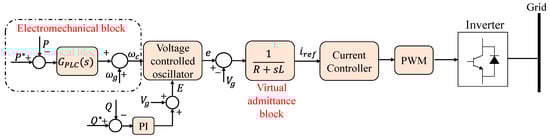
Figure 11. Synchronous power controller (SPC) control diagram [6].
The nested loop structure, on the other hand, makes setting the control system parameters more difficult. Furthermore, with an over-damped response, a second-order representation is provided as an alternative to employing the swing equation for inertia emulation. This helps to minimize the system’s oscillations [36]. The authors of [37] offered improved versions of this second-order model.
2.3. Inducverters
Another type of inertia simulation control technology is the inducverter. The inducverter’s principle is established mostly on an induction machine’s inertial characteristics. A self-starting and soft-starting induction machine is available. It has the ability to synchronize with the utility grid and follow changes to the utility grid. The inducverter uses the same principles to simulate inertia. An inducverter’s active power and frequency can be altered using power electronic inverter-based virtual rotor inertia [6,38]. An inverter with a filter makes up the electrical portion of the inducverter, along with a control portion that makes the inverter behave as an induction machine by generating the voltage signals, as illustrated in Figure 12. This approach offers the benefit of automatic synchronization without a phase-locked loop (PLL).
2.4. Virtual Oscillator Control (VOC)
Another VSM topology is the virtual oscillator controller (VOC), which synchronizes DG units devoid of any kind of communication by implementing a non-linear oscillator inside the controller rather than simulating SG or induction generators. This strategy is especially advantageous in a grid controlled by DGs, because the controller is capable of maintaining synchronism and sharing the overall system load [18,39].
2.5. Frequency–Power Response-Based Topologies
The easiest method of simulating inertia is to use a frequency–power response-based architecture [18]. This architecture is not incorporated into any synchronous generator modeling.
Virtual-Synchronous Generators (VSG)
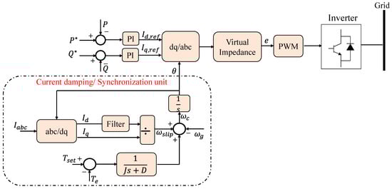
The inertial responding properties of an SG in a DG network, particularly its capacity to adapt to frequency variations, are mimicked by virtual-synchronous generators (VSG). This simulates the kinetic energy’s production or absorbing in the same way as an SG does, allowing the DG units to be dispatched. The VSG technique, in contrast to classic droop controllers that simply allow frequency regulation, may offer frequency control. This control is based on the frequency measurement’s derivative and is similar to an SG’s inertial power generation or absorption in a power imbalance. As a result, the VSG, then, is a dispatchable distributed generation that adjusts its output in response to variations in system frequency. Since it does not include all the complicated equations needed in an SG, VSG is among the easiest ways to apply virtual inertia. Using several DG units as current sources, on the other hand, is known to cause instability. Equation (6) is used to adjust the VSG converter’s output power:
where, Δω is the change in angular frequency, dΔωdt is rate-of-change in angular frequency, KD is the damping constant, and KI is the inertial constant. The ROCOF is stopped by the inertial constant, and this, based on the frequency derivative, provides a quick dynamic frequency response. In an isolated grid, this functionality is particularly critical, given that the initial ROCOF might be quite large, causing protective relays to be unnecessarily triggered. Figure 13 depicts the structure of the VSG. The system frequency change and ROCOF are measured using a PLL. For the inverter, the active power reference is then calculated using Equation (6). On this basis, references for the current controller are created [40].
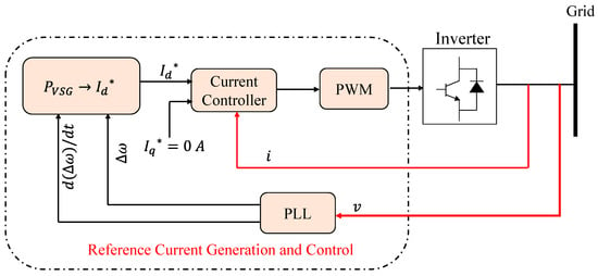
Figure 13. Virtual-synchronous generator (VSG) topology [18].
The architecture shown here uses a direct and quadrature axis d−q current control method, although any alternative current control method can be employed. The d-axis current reference for d−q control may be computed as:
where Vd and Vq are the dq parts of the observed grid voltage, v, respectively. As the active power is regulated only, the q-axis current reference, Iq, and the reactive power, Q, are both set to zero. The gate signals to operate the inverter are produced by the current controller, which is established on grid current feedback. As a result, the inverter functions as a voltage source inverter with current control.
Another sort of VSG used to simulate the inertial features of an SG is the VSYNCH’s VSG. It can respond to variations in frequency. The block diagram of the VSYNCH’s VSG is presented in Figure 14. In the inertial response, the control method creates a control signal to add, from the storage device, the needed quantity of power. The VSG acts as a current control source, simulating inertia. The PLL is built in such a way so that it produces the ROCOF and Δω in this case [6].
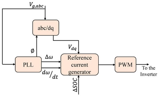
Figure 14. VSYNCH’s virtual-synchronous generator block diagram [6].
2.6. Droop-Based Approaches
To increase inertial responsiveness of inverter-dominated power systems, the techniques reported until now attempt to emulate or simulate the SG’s performance. For the autonomous functioning of isolated microgrid systems, frequency droop-based controllers have been created [18], which differ from existing strategies. The frequency droop is accomplished as follows, assuming that the grid’s impedance is inductive:
where Pin represents the active power reference, Pout represents the DG unit output measured active power, mp represents the active power droop, ω∗ represents the reference frequency, and ωg represents the local grid frequency. The voltage droop is implemented in the same way:
where, v∗ represents the reference voltage, vg represents the grid voltage, Qin represents the reference reactive power, Qout represents the DG unit output measured reactive power, and mq represents the reactive power droop. Figure 15 depicts the architecture of the method based on Equation (8). To measure the inverter output power and to attenuate high-frequency parts from the inverter output, a low-pass filter with a time constant Tf is frequently employed [18]. The filters employed in these controllers for power measurements create a delay that is mathematically comparable to the virtual inertia, whereas the droop gain is comparable to damping. Conventional droop-based systems, such as those explained in (8) and (9), are known to possess a delayed transient reaction. There have been suggestions for ways to enhance droop controllers, by employing virtual output impedance or increasing the dynamic performance of the droop structure.
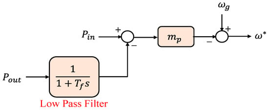
Figure 15. Frequency droop control [18].
Finally, Table 1 summarizes the key features of each VSM topology. The summary highlights the key information of each topology. Virtual inertia models built on synchronous generators have the advantage of being an exact copy of synchronous generator dynamics. In a synchronous generator-based approach, PLL is used for phase synchronization and frequency derivatives are not necessary. These topologies lack over-current protection and have numerical instability as drawbacks. In contrast to SG-based models, swing equation-based models are easier to understand. PLL is only utilized for phase synchronization in these topologies, and frequency derivatives are not necessary. Power and frequency fluctuations as well as a lack of over-current safety are some of these topologies’ drawbacks. The construction of the frequency–power approach-based model, on the other hand, is simple since it uses a standard current-source implementation and includes built-in over-current protection. Due to PLL, these topologies are insecure, most often in weak grids. The frequency–power method is a model that is subject to noise.
Table 1. Key features of VSM topologies.
| Topologies | Type | Ref. | Features | Strength | Weaknesses | PLL |
|---|---|---|---|---|---|---|
| Synchronverters | Synchronous Generator Model-Based Topology | [6,23,26,27] |
|
|
|
Required for initial synchronization |
| Kawasaki Heavy Industries (KHI) | Synchronous Generator Model-Based Topology | [18,28,29] |
|
|
||
| VISMA and IEPE topologies | Synchronous Generator Model-Based Topology | [23,30,31] |
|
VISMA:
|
VISMA:
|
Required for initial synchronization |
| Ise Labs Topology | A Swing Equation-Based Topology | [18,32,33] |
|
|
|
Required for initial synchronization |
| Synchronous Power Controller (SPC) | A Swing Equation-Based Topology | [6,34,35,36,37] |
|
|
|
|
| Inducverters | [6,38] |
|
|
|||
| Virtual Oscillator Control (VOC) | [18,39] |
|
|
|||
| VSYNC VSG Topology | Frequency–Power Response-Based | [6,18,40] |
|
|
|
Needed |
| Droop-Based Approaches | [18] |
|
|
Needed |
This entry is adapted from the peer-reviewed paper 10.3390/en15228406
This entry is offline, you can click here to edit this entry!