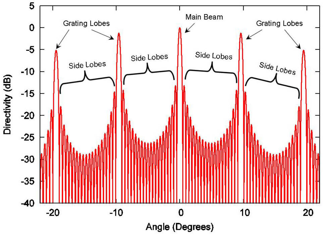
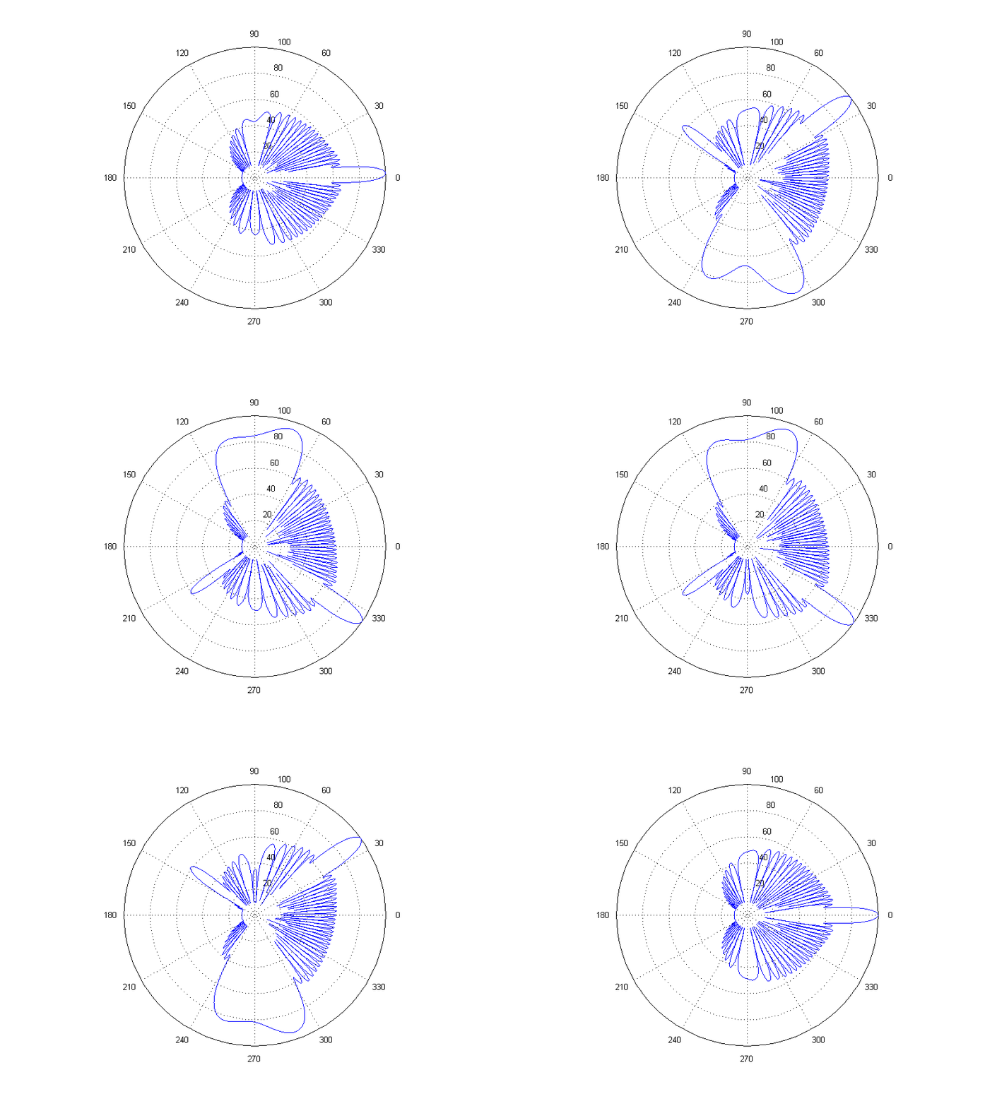
In antenna engineering, side lobes or sidelobes are the lobes (local maxima) of the far field radiation pattern of an antenna or other radiation source, that are not the main lobe. The radiation pattern of most antennas shows a pattern of "lobes" at various angles, directions where the radiated signal strength reaches a maximum, separated by "nulls", angles at which the radiated signal strength falls to zero. This can be viewed as the diffraction pattern of the antenna. In a directional antenna in which the objective is to emit the radio waves in one direction, the lobe in that direction is designed to have a larger field strength than the others; this is the "main lobe". The other lobes are called "side lobes", and usually represent unwanted radiation in undesired directions. The side lobe directly behind the main lobe is called the back lobe. The longer the antenna relative to the radio wavelength, the more lobes its radiation pattern has. In transmitting antennas, excessive side lobe radiation wastes energy and may cause interference to other equipment. Another disadvantage is that confidential information may be picked up by unintended receivers. In receiving antennas, side lobes may pick up interfering signals, and increase the noise level in the receiver. The power density in the side lobes is generally much less than that in the main beam. It is generally desirable to minimize the sidelobe level (SLL), which is measured in decibels relative to the peak of the main beam. The main lobe and side lobes occur for both transmitting and receiving. The concepts of main and side lobes, radiation pattern, aperture shapes, and aperture weighting, apply to optics (another branch of electromagnetics) and in acoustics fields such as loudspeaker and sonar design, as well as antenna design. Because an antenna's far field radiation pattern is a Fourier Transform of its aperture distribution, most antennas will generally have sidelobes, unless the aperture distribution is a Gaussian, or if the antenna is so small as to have no sidelobes in the visible space. Larger antennas have narrower main beams, as well as narrower sidelobes. Hence, larger antennas have more sidelobes in the visible space (as the antenna size is increased, sidelobes move from the evanescent space to the visible space).
- sidelobe level
- far field radiation
- directional antenna
1. Sidelobes for Case of Uniformly-Illuminated Aperture
For a rectangular aperture antenna having a uniform amplitude distribution (or uniform weighting), the first sidelobe is −13.26 dB relative to the peak of the main beam. For such antennas the radiation pattern has a canonical form of
[math]\displaystyle{ \displaystyle\text{Radiation Pattern (in units of dB)} \propto 20\log_{10}\left|\frac{\sin X}{X}\right| }[/math]
Simple substitutions of various values of X into the canonical equation yield the following results:
For a circular aperture antenna, also having a uniform amplitude distribution, the first sidelobe level is −17.57 dB relative to the peak of the main beam. In this case, the radiation pattern has a canonical form of
[math]\displaystyle{ \displaystyle\text{Radiation Pattern (in units of dB)} \propto 10\log_{10}\left|2\cdot\frac{J_1(X)}{X}\right|^2 }[/math]
where [math]\displaystyle{ \displaystyle J_1(x) }[/math] is the Bessel function of the first kind of order 1. This is known as the Airy pattern. Simple substitutions of various values of X into the canonical equation yield the following results:
A uniform aperture distribution, as provided in the two examples above, gives the maximum possible directivity for a given aperture size, but it also produces the maximum side lobe level. Side lobe levels can be reduced by tapering the edges of the aperture distribution (changing from uniformity) at the expense of reduced directivity.
The nulls between sidelobes occur when the radiation patterns passes through the origin in the complex plane. Hence, adjacent sidelobes are generally 180° out of phase to each other.
2. Grating Lobes

For discrete aperture antennas (such as phased arrays) in which the element spacing is greater than a half wavelength, the spatial aliasing effect causes some sidelobes to become substantially larger in amplitude, and approaching the level of the main lobe; these are called grating lobes, and they are identical, or nearly identical in the example shown, copies of the main beams.
Grating lobes are a special case of a sidelobe. In such a case, the sidelobes should be considered all the lobes lying between the main lobe and the first grating lobe, or between grating lobes. It is conceptually useful to distinguish between sidelobes and grating lobes because grating lobes have larger amplitudes than most, if not all, of the other side lobes. The mathematics of grating lobes is the same as of X-ray diffraction.

The content is sourced from: https://handwiki.org/wiki/Physics:Side_lobe
