Your browser does not fully support modern features. Please upgrade for a smoother experience.
Please note this is an old version of this entry, which may differ significantly from the current revision.
Temperature-to-Digital Converters (TDCs) are on-chip sensors that generate temperature-dependent digital codes.
- temperature
- TDCs
- smart sensors
- integrated circuits
1. Introduction
On-chip temperature measurements have acquired an increasingly important role over the past two decades, especially if we consider sensors that produce data in the digital domain, referred to as Temperature-to-Digital Converters (TDCs). The growing computational power of modern microprocessors has given rise to a higher degree of criticality in their thermal management process [1]; for instance, dynamic voltage and frequency scaling (DVFS), a commonly used approach in this framework [2], requires responsive temperature tracking to allow an effective control on the thermal status of the microprocessor and, furthermore, the cooling fans’ speed regulation is also based on a continuous temperature monitoring [3][4][5]. Another field that has featured a remarkable growth in recent years is the Micro-Electro-Mechanical Systems (MEMS) one [6]; the employment of these devices for Internet of Things (IoT) applications, supported by a parallel technological development, has led the research focus to more and more robust devices with respect to the influence of environmental effects. One of the main challenges is, indeed, to mitigate the impact of the ambient temperature on the performance of these devices; the micro-structures used as sensing elements suffer from a significant thermal spread causing a degradation of the reliability of the sensed quantity. For this reason, high-precision MEMS devices also require a temperature tracking to compensate for the drift of their parameters [7][8][9][10][11]. Integrated temperature sensors are also used for clinical applications [12][13][14]; devices that provide a high accuracy monitoring in the human body temperature range are needed for the detection of atypical biomedical conditions. Lastly, since temperature is a fundamental physical parameter of both industry and everyday life, on-chip temperature measurements are also combined with radio-frequency identification (RFID) tags in several applications: monitoring of the food cold chain [15][16], environmental monitoring [17][18], supply chain management of healthcare products [19], animal healthcare monitoring [20] and many more.
2. Temperature-to-Digital Converters
There are a lot of applications requiring on-chip temperature sensing, as seen in the introduction, and concern several systems in the microelectronics field; despite their wide range, all the reported examples [3][4][5][7][8][9][10][11][12][13][14][15][16][17][18][19][20] have one important feature in common: they provide temperature information in the form of digital data. This is fundamental as it makes them compatible for a direct communication with digital signal processing (DSP) circuits that can easily handle the needed temperature information and at the same time reduces the complexity of the system they are inserted in; for this reason, they are often referred to as smart temperature sensors [21] or as Temperature-to-Digital Converters (TDCs). It is important to specify that this category of temperature sensors was born with a cost-minimization perspective and that its development in the past two decades has consequently followed this line; even if, in principle, these fully integrated temperature sensors have significant limitations in terms of accuracy and sensing range with respect to other existing discrete sensors, their great success is related to their compatibility with large-scale production of low-cost products being integrated within the system in which they are operated. Figure 1 shows the conceptual diagram of a TDC.
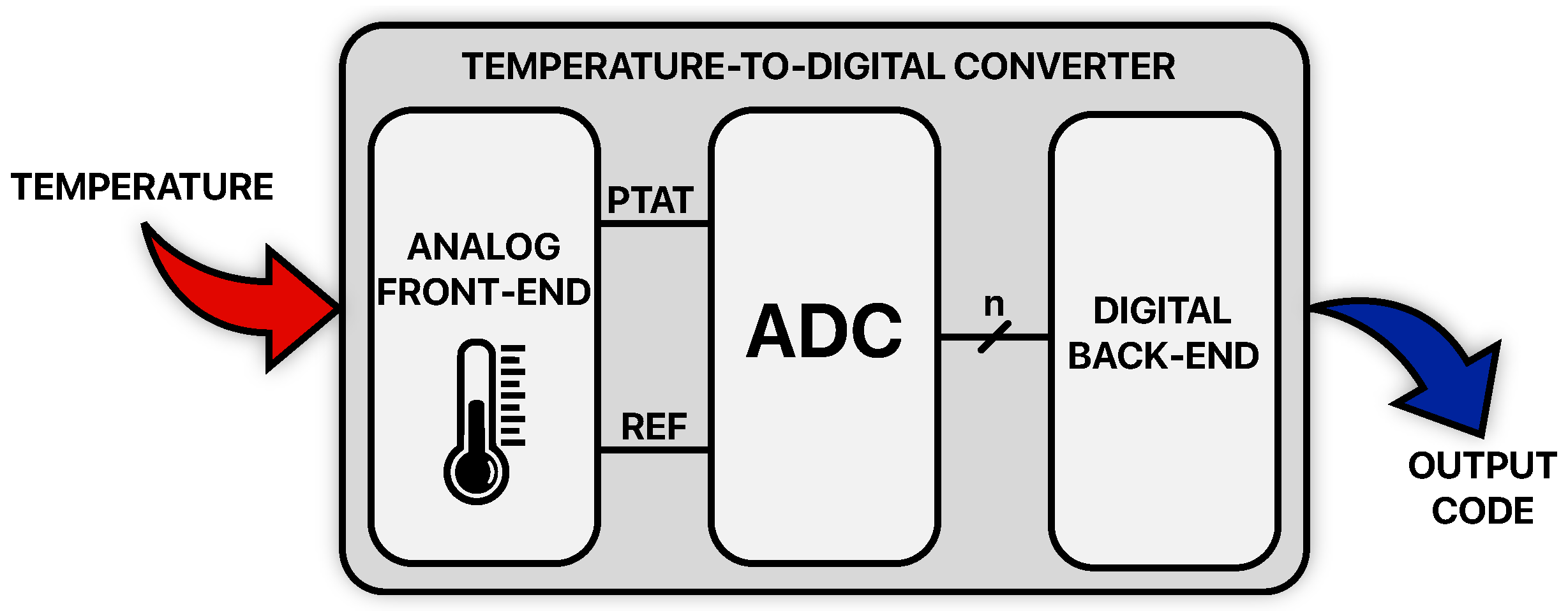
Figure 1. Conceptual diagram of a Temperature-to-Digital Converter.
It is composed of an Analog Front-End (AFE), an Analog-to-Digital Converter (ADC) and a Digital Back-End (DBE). The TDC’s input signal is temperature; the AFE, the first block of the chain, is responsible to sense it achieving an electrical form for it (either in the voltage or in the current domain) and to generate at its output the signals needed for the Analog-to-Digital conversion: a proportional-to-absolute-temperature (PTAT) signal which contains the information to be converted and a reference (REF) signal, which in principle is a Zero-Temperature-Coefficient (ZTC) signal, with respect to which the conversion is carried out. Those signals enter the ADC which produces PTAT digital words with an intrinsic n-bit resolution and with a data rate (fS) that depends on the converter architecture; this operation is typically performed without the use of sample and hold (S/H) circuits because of the relative slowness of the temperature signal with respect to the common conversion rates of ADCs. The n-bit codes are then processed by the DBE that, in fact, acts as an oversampler; it refines their intrinsic resolution performing decimation and filtering with a certain OverSampling Ratio (OSR) in order to obtain the output codes of the TDC which feature a higher resolution at the cost of a lower data rate (fS/OSR).
The resulting time interval required to perform a single Temperature-to-Digital conversion is therefore given by
Considering the TDC’s minimum working supply voltage (Vsy) and the current drained from it (Isy), its conversion energy can be defined as
It is a parameter of paramount importance together with the TDC’s resolution (Res) which is the minimum temperature difference that can correctly be detected and which is determined by the quantization noise of the ADC, by the electronic noise (thermal, flicker, etc.) and by Tconv itself. Another parameter of interest is the temperature inaccuracy (IA); in absolute form, it is a statistical evaluation of the worst case (or ±3σ) temperature error and, introducing the TDC conversion range (Trange), its relative form can be expressed as
This quantity is strongly dependent on the number of controlled temperatures at which the TDC gets trimmed (ntrim) [22][23], an unavoidable procedure in most applications; the trimming process, which basically consists of calibrating the sensed temperature error, is a cost of great relevance in the TDC framework as heating and cooling the devices to be trimmed is a very time consuming operation. For this reason, ntrim should be minimized to preserve the cost-effectiveness of the sensor.
Due to the presence of this great variety of parameters of interest, several Figures of Merit (FoMs) have been introduced to provide TDC performance metrics in a synthetic way and from specific perspectives:
(4) and (5), presented in [24], involve the TDC conversion energy together with its resolution or its inaccuracy, respectively. (6), instead, addresses only the production cost of the TDC (Area is the active silicon area of the device, F is the feature size of the adopted technological process) while (7) provides a global overview of the TDC performance [25].
Several ADC architectures have been used, in literature, to be included in TDCs; there are examples of Flash-based TDCs [26][27], of SAR-based ones [11][28], of ΣΔ-based ones [5][14], of time/frequency-domain-based ones [22][29] or of hybrid solutions [30][31]. It is important to notice that even if, conceptually, Flash ADCs and SAR ADCs are faster for a given quantization noise and clock frequency, to overcome the limits imposed by the presence of thermal noise, their output codes still need to be processed by the DBE and therefore, for the same amount of power consumption, are not automatically at a higher energy efficiency level with respect to the ΣΔ-based or the time/frequency-domain-based alternatives. Actually, thanks to their versatility, ΣΔ converters are the most used ones in the case of AFEs generating static temperature-dependent signals while time/frequency-domain-based ADCs are preferred in the case of dynamic temperature-dependent signals.
This entry is adapted from the peer-reviewed paper 10.3390/mi13112025
References
- Rupp, K. 42 Years of Microprocessor Trend Data. Available online: www.karlrupp.net/2018/02/42-years-of-microprocessor-trend-data (accessed on 5 October 2022).
- Sheikh, H.F.; Ahmad, I.; Wang, Z.; Ranka, S. An overview and classification of thermal-aware scheduling techniques for multi-core processing systems. Sustain. Comput. Inform. Syst. 2012, 2, 151–169.
- Shor, J.S.; Luria, K. Miniaturized BJT-Based Thermal Sensor for Microprocessors in 32- and 22-nm Technologies. IEEE J. Solid-State Circuits 2013, 48, 2860–2867.
- Oshita, T.; Shor, J.S.; Duarte, D.E.; Kornfeld, A.; Zilberman, D. Compact BJT-Based Thermal Sensor for Processor Applications in a 14 nm tri-Gate CMOS Process. IEEE J. Solid-State Circuits 2015, 50, 799–807.
- Bass, O.; Shor, J. A Miniaturized 0.003 mm2 PNP-Based Thermal Sensor for Dense CPU Thermal Monitoring. IEEE Trans. Circuits Syst. I: Regul. Pap. 2020, 67, 2984–2992.
- Yanazawa, H.; Homma, K. Growing market of MEMS and technology development in process and tools specialized to MEMS. In Proceedings of the 2017 IEEE Electron Devices Technology and Manufacturing Conference (EDTM), Toyama, Japan, 28 February–2 March 2017; pp. 143–144.
- Chen, L.T.; Lee, C.Y.; Cheng, W.H. MEMS-based humidity sensor with integrated temperature compensation mechanism. Sens. Actuators A Phys. 2008, 147, 522–528.
- Salvia, J.C.; Melamud, R.; Chandorkar, S.A.; Lord, S.F.; Kenny, T.W. Real-Time Temperature Compensation of MEMS Oscillators Using an Integrated Micro-Oven and a Phase-Locked Loop. J. Microelectromechanical Syst. 2010, 19, 192–201.
- Zotov, S.A.; Simon, B.R.; Trusov, A.A.; Shkel, A.M. High Quality Factor Resonant MEMS Accelerometer with Continuous Thermal Compensation. IEEE Sens. J. 2015, 15, 5045–5052.
- Zaliasl, S.; Salvia, J.C.; Hill, G.C.; Chen, L.; Joo, K.; Palwai, R.; Arumugam, N.; Phadke, M.; Mukherjee, S.; Lee, H.C.; et al. A 3 ppm 1.5 × 0.8 mm² 1.0 µA 32.768 kHz MEMS-Based Oscillator. IEEE J. Solid-State Circuits 2015, 50, 291–302.
- Aprile, A.; Folz, M.; Gardino, D.; Malcovati, P.; Bonizzoni, E. A Compact 2.5-nJ Energy/Conversion NPN-Based Temperature-to-Digital Converter with a Fully Current-Mode Processing Architecture. In Proceedings of the 48th European Solid-State Circuits Conference (ESSCIRC), Milan, Italy, 19–22 September 2022; pp. 473–476.
- Vaz, A.; Ubarretxena, A.; Zalbide, I.; Pardo, D.; Solar, H.; Garcia-Alonso, A.; Berenguer, R. Full Passive UHF Tag with a Temperature Sensor Suitable for Human Body Temperature Monitoring. IEEE Trans. Circuits Syst. II Express Briefs 2010, 57, 95–99.
- Law, M.K.; Lu, S.; Wu, T.; Bermak, A.; Mak, P.; Martins, R.P. A 1.1 µW CMOS Smart Temperature Sensor with an Inaccuracy of ±0.2 °C (3σ) for Clinical Temperature Monitoring. IEEE Sens. J. 2016, 16, 2272–2281.
- Pan, S.; Makinwa, K.A.A. A 6.6-µW Wheatstone-Bridge Temperature Sensor for Biomedical Applications. IEEE Solid-State Circuits Lett. 2020, 3, 334–337.
- Law, M.K.; Bermak, A.; Luong, H.C. A Sub-µW Embedded CMOS Temperature Sensor for RFID Food Monitoring Application. IEEE J. Solid-State Circuits 2010, 45, 1246–1255.
- Wang, B.; Law, M.K.; Bermak, A.; Luong, H.C. A Passive RFID Tag Embedded Temperature Sensor with Improved Process Spreads Immunity for a −30 °C to 60 °C Sensing Range. IEEE Trans. Circuits Syst. I Regul. Pap. 2014, 61, 337–346.
- Cho, N.; Song, S.J.; Kim, S.; Kim, S.; Yoo, H.J. A 5.1-µW UHF RFID tag chip integrated with sensors for wireless environmental monitoring. In Proceedings of the 31st European Solid-State Circuits Conference (ESSCIRC), Grenoble, France, 12–16 September 2005; pp. 279–282.
- Shen, H.; Li, L.; Zhou, Y. Fully integrated passive UHF RFID tag with temperature sensor for environment monitoring. In Proceedings of the 7th International Conference on ASIC (ASICON), Guilin, China, 22–25 October 2007; pp. 360–363.
- Yin, J.; Yi, J.; Law, M.K.; Ling, Y.; Lee, M.C.; Ng, K.P.; Gao, B.; Luong, H.C.; Bermak, A.; Chan, M.; et al. A System-on-Chip EPC Gen-2 Passive UHF RFID Tag with Embedded Temperature Sensor. IEEE J. Solid-State Circuits 2010, 45, 2404–2420.
- Opasjumruskit, K.; Thanthipwan, T.; Sathusen, O.; Sirinamarattana, P.; Gadmanee, P.; Pootarapan, E.; Wongkomet, N.; Thanachayanont, A.; Thamsirianunt, M. Self-powered wireless temperature sensors exploit RFID technology. IEEE Pervasive Comput. 2006, 5, 54–61.
- Bakker, A. CMOS smart temperature sensors—An overview. IEEE Sens. J. 2002, 2, 1423–1427.
- Li, J.; Lin, Y.; Ning, N.; Yu, Q. A +0.44 °C/−0.4 °C Inaccuracy Temperature Sensor with Multi-Threshold MOSFET-Based Sensing Element and CMOS Thyristor-Based VCO. IEEE Trans. Circuits Syst. I Regul. Pap. 2021, 68, 1102–1113.
- Aprile, A.; Folz, M.; Gardino, D.; Malcovati, P.; Bonizzoni, E. A One-Point Exponential Trimming Technique for an Effective Suppression of Process Spread in BJT-based Temperature Processing Circuits. In Proceedings of the 2022 IEEE International Symposium on Circuits and Systems (ISCAS), Austin, TX, USA, 28 May–1 June 2022; pp. 881–884.
- Makinwa, K.A.A. Smart temperature sensors in standard CMOS. Procedia Eng. 2010, 5, 930–939.
- Aprile, A.; Moisello, E.; Bonizzoni, E.; Malcovati, P. An Extensive Investigation and Analysis of Temperature-to-Digital Converter FoMs. In Proceedings of the 28th IEEE International Conference on Electronics, Circuits, and Systems (ICECS), Dubai, United Arab Emirates, 28 November–1 December 2021; pp. 1–4.
- Zjajo, A.; Barragan, M.J.; de Gyvez, J.P. Low-Power Die-Level Process Variation and Temperature Monitors for Yield Analysis and Optimization in Deep-Submicron CMOS. IEEE Trans. Instrum. Meas. 2012, 61, 2212–2221.
- Shim, D.; Jeong, H.; Lee, H.; Rhee, C.; Jeong, D.K.; Kim, S. A Process-Variation-Tolerant On-Chip CMOS Thermometer for Auto Temperature Compensated Self-Refresh of Low-Power Mobile DRAM. IEEE J. Solid-State Circuits 2013, 48, 2550–2557.
- Pelzers, K.; Xin, H.; Cantatore, E.; Harpe, P. A 2.18-pJ/conversion, 1656-µm2 Temperature Sensor with a 0.61-pJ·K2 FoM and 52-pW Stand-By Power. IEEE Solid-State Circuits Lett. 2020, 3, 82–85.
- Chen, P.; Hu, Y.; Liou, J.; Ren, B. A 486 kS/s CMOS Time-Domain Smart Temperature Sensor with −0.85 °C/0.78 °C Voltage-Calibrated Error. In Proceedings of the 2015 IEEE International Symposium on Circuits and Systems (ISCAS), Lisbon, Portugal, 24–27 May 2015; pp. 2109–2112.
- Chen, P.; Chen, C.C.; Peng, Y.H.; Wang, K.M.; Wang, Y.S. A Time-Domain SAR Smart Temperature Sensor with Curvature Compensation and a 3σ Inaccuracy of −0.4 °C ∼ +0.6 °C Over a 0 °C to 90 °C Range. IEEE J. Solid-State Circuits 2010, 45, 600–609.
- Park, H.; Kim, J. A 0.8-V Resistor-Based Temperature Sensor in 65-nm CMOS with Supply Sensitivity of 0.28 °C/V. IEEE J. Solid-State Circuits 2018, 53, 906–912.
This entry is offline, you can click here to edit this entry!