Your browser does not fully support modern features. Please upgrade for a smoother experience.
Please note this is an old version of this entry, which may differ significantly from the current revision.
Subjects:
Energy & Fuels
The transition process of the low-lift pump mainly refers to the start–stop process. Due to the opening and closing of the gate, the sudden change in the flow velocity in the pipeline causes the water hammer phenomenon. This hydraulic process is called the transition process. Experience shows that hydraulic machinery accidents mainly occur in the transition process. Therefore, the study of the start–stop transition process of the pump has an important guiding significance for the safe operation of the pumping station.
- large low-lift pump station
- transition process
- research methods
1. Research Status of Transition Process of Low-Head Pumping Station
In the transition process of starting and stopping a low-lift pump, there may be problems such as increased speed and dramatic changes in the pump’s internal and external characteristics, which will produce hydraulic excitation, pressure pulsation, and so on. In the process of starting the pump, because it is necessary to open the gate, and since a quickly opening gate is a common way to stop the flow of the pump device, there will be a matching problem between the fast gate and the runner’s starting speed during the starting process of the pump. For example, consider the starting time of the fast gate and the relationship between the starting speed and the starting time and starting speed of the runner: the phenomenon of water backflow will occur when the fast gate is opened earlier; if it is opened late, the unit head will increase sharply, resulting in the pump’s start failure. In the shutdown process, if power failure occurs due to an accident and the gate closes too late, the operation of the pump station will be the pump conditions in turn through the braking conditions, turbine conditions, and ultimately to runaway. Among these failures, the water backflow caused by the pump’s reversal, which can thus lead to drive motor reversal, will cause water hammer, motor damage, and other accidents. The runaway speed is far greater than the speed under design conditions, and will cause severe vibration of the unit and pressure pulsation [9]. When the unit starts and stops, the drastic change in water flow causes the water hammer phenomenon. Water hammer will cause a sharp change in the internal pressure of the unit, causing damage to the unit’s components and affecting the stable operation of the unit. The authors of [10,11,12,13] studied the pressure fluctuation characteristics of a pump based on the CFD method and observed that the hydraulic excitation force of the pump is the main cause of dynamic stress fluctuation.
2. Start-up Process Research
Domestic and foreign scholars have conducted a lot of research on several transition processes of pumps, wherein the pump transition process mainly refers to a pump’s start–stop process. The actions involved in the start-up process of the pump is the start-up of the impeller and the opening of the gate. The different opening times and opening speeds between the two have an important influence on the internal and external characteristics of the pump device during the start-up process. In addition, some gates have also been equipped with patter doors to shunt and reduce the head of the start-up process, which is related to the stability of the unit. The research on the starting transition process of low-lift pumps will help further the development of low-lift tubular pump units, especially in the east route of the south-to-north water transfer project.
To study the evolution of unsteady flow in the start-up process of centrifugal pumps, Z Zhu et al. [14] used the external characteristics test and an internal flow-focused numerical calculation of centrifugal pumps to obtain the relationship between speed, capacity, head, and start-up time through external characteristic experiments. The velocity and pressure distribution in the pump channel was obtained by numerical calculation. The calculation results show that the internal flow characteristics are in good agreement with the experimental results and numerical calculations of the external characteristics, which lays a foundation for the diagnosis of the centrifugal pump during transient operations. Based on the asynchronous starting characteristics of the three-phase salient pole synchronous motor, combined with the hydraulic characteristics of the shaft tubular pump device and the dynamic characteristics of the pump unit, Zhang Jinpeng established a mathematical model of the starting transition process of a shaft tubular pump station [15]. Through Simulink simulation software, various characteristics in the starting transition process were studied in depth. S.F. Fu et al. [16] studied the transient characteristics of an axial flow pump during start-up using sliding mesh and pressure coupling, and the results were in good agreement with the experimental results. The results show that the transient characteristic parameters such as the rotational speed, head, and flow rate of the pump change significantly during the start-up process. The pressure distribution of the impeller blade changes obviously, and the vortex core area increases gradually. Kan K et al. [17] designed and verified a method of reinforcing impeller blade roots to increase the strength of the blades and minimize their impact on hydraulic performance, which can be used to improve the stability of the structural design stage of hydraulic machinery blades. W Li et al. [18] studied the vibration characteristics of the runner during start-up. The results show that the combined effect of the complex hydrodynamic environment and the centrifugal force of the impeller during the start-up and acceleration process makes the deformation and dynamic stress of the blade increase in a reciprocating oscillation trend. The rapid change in the rotational speed exacerbates the vibration problem around the tip area of the blade, which leads to excessive stress concentration and damage at the root of the blade. Li, Z. F. and Hu, F. F. et al. [19,20,21,22] studied the internal flow characteristics of the centrifugal pump during start-up. In order to obtain the internal flow field and observe the evolution of the transient internal flow in the impeller, the three-dimensional unsteady, incompressible viscous flow during the start-up of the centrifugal pump was studied by computational fluid dynamics (CFD), as shown in Figure 4. The dynamic mesh (DM) method with non-conformal mesh boundaries was applied to obtain the external characteristics and internal flow field.
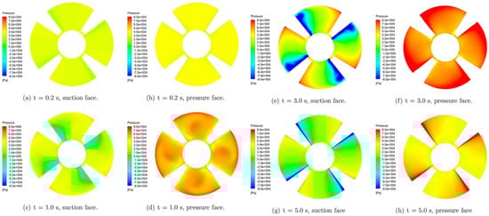
Figure 4. Pressure change on impeller during startup [16].
The impeller speed and the time and speed of the gate’s opening play a decisive role in the transition process. Long Yun et al. [23] studied the start-up process of a multi-stage centrifugal pump, which is divided into two stages: the closing valve conversion and opening valve conversion. The authors analyzed the characteristics of the pump and the evolution of the internal flow field. Yang [24] studied the influence of the gate-opening speed and opening time delay on various parameters during the start-up process of a tubular pump. The results show that an appropriate acceleration of the gate-opening speed and delay in the gate opening time can improve the starting characteristics of the pump device, which is beneficial to the start-up process. By calculating the influence of the opening speed of the gate on the system under the most unfavorable conditions, Wang Changhong et al. [25] observed that with the extension of the opening time of the gate, the maximum backflow decreases gradually, and the maximum starting power increases gradually. In the case of motor power, the opening time of the gate can be reasonably selected. Xu et al. [26] studied the change in the external characteristic parameters and flow patterns during the start-up process of the gate of a large-scale tubular pumping station unit at 10 times the design speed. It was found that the speed and flow of the unit would reach the rated speed and rated flow faster, but at the same time, the maximum backflow flow increased by 30% compared with the non-accelerated start-up. Ji Y Y et al. [27] studied the hydraulic performance under three states of fast, medium, and slow start-up times at a very low flow rate and revealed the transient characteristics of the pump during start-up. The results show that the similarity law of the pump is suitable for the transient process’s performance prediction with a long start-up time.
As a commonly used flow-breaking device in pumping stations, the flap gate has the effect of shunting and reducing the starting head during a pump’s start-up. Li Yingchao and Xu Hui et al. [28,29] established a dynamic torque balance equation for the hydraulic characteristics of the start-up transition process of the fast gate with the opening of the flap gate. Figure 5 shows the change rule of the gate and flap gate. The results show that the gate with the additional flap gate can reduce the maximum head during the start-up process and can also provde a good diversion effect in order to avoid the instability of the unit caused by the sudden change in pressure on both sides when the gate is opened instantaneously. According to the pump station unit in the start-up process concerning a frequent start-up failure phenomenon, and the analysis of the existence of the asynchronous operation of a motor that cannot move into the synchronization phase, Yu Qiqing [30] put forward research on the fast gate type concerning the feasibility of adding a door, and pointed out that after adding the door, it is appropriate to reduce the lifting speed of the gate and reduce the opening time delay to improve the efficiency of the pump station.
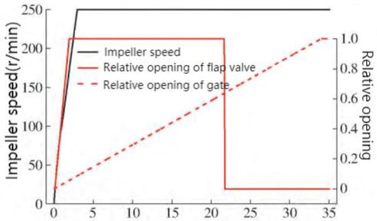
Figure 5. The variation law of impeller speed, relative opening of fast gate, and flap gate [30].
To investigate the transient characteristics of the large vertical siphon axial flow pump station during the start-up and exhaust process, Zhang et al. [31] numerically simulated the start-up process of an axial flow pump station under the two start-up modes of pre-opening the vacuum-breaking valve and keeping the vacuum-breaking valve closed. The start-up transition process of the siphon axial flow pump from start-up to stable operation is divided into four stages, as shown in Figure 6. The water flow over the hump from the start-up of the unit to the rising of the hump is defined as the hydraulic gas drive stage. The water level from the hump to the bottom of the hump is defined as the weir flow stage. The water level from the bottom of the hump to the top of the hump before emptying is defined as the siphon formation stage. Air discharge in the pump device and the achievement of full pipe flow are defined as the stable operation stage. Wu et al. [32] studied the external transient hydrodynamic performance and internal flow mechanism of the pump during the rapid opening of the discharge valve.
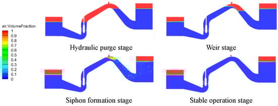
Figure 6. Stage division in the exhaust process [31].
3. Shutdown Process Research
The transition process of a pump’s shutdown includes a normal shutdown and an accidental shutdown. Most scholars study accidental shutdowns, that is, runaway conditions. Runaway means that in the process of stopping the pump, the sudden power failure of the pump unit or other unit causes an accidental shutdown, and the locking device (fast gate, flap gate, etc.) refuses to operate, which will cause the speed to decrease and the flow to decrease. Until a certain time, the flow rate of the unit is reduced to zero, and then the unit enters the braking condition. The water flow flows backward, and the flow rate gradually increases. The unit speed continues to decline until it drops to zero. After that, the impeller begins to rotate in the reverse direction of the turbine, and the speed continues to rise. Finally, it reaches the runaway state. The runaway speed exceeds the rated speed several times, which may exceed the safety range and cause damage to the unit [33]. The four-quadrant operating characteristics of the pump are shown in Figure 7.
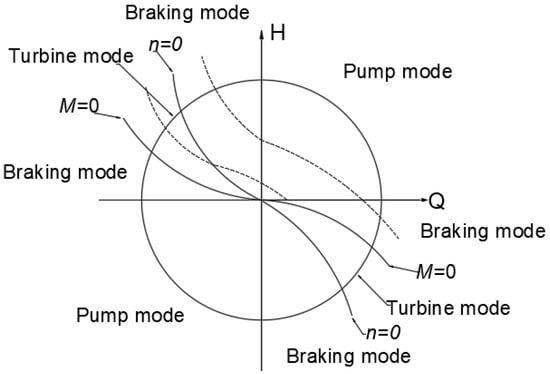
Figure 7. Four-quadrant operation characteristic curve.
Yang Lin et al. [34] studied the shutdown transition process of large-scale low-lift pumping stations. During the shutdown process, the axial flow pump unit will enter the pump’s working conditions, the brakes’ working conditions, and, in turn, the turbine’s working conditions. After the fast gate is closed, the blade torque and the blade axial force will oscillate, which can easily induce a lift accident. To explore the instantaneous flow characteristics of the pump under unsteady conditions, K Kan et al. [35] used the three-dimensional VOF method to simulate the water surface of the upstream and downstream reservoirs, carried out numerical simulation and model testing on the whole flow channel, and studied the runaway process caused by the power failure of the unit. During the shutdown process, the external characteristic parameters of the unit changed, as shown in Figure 8.
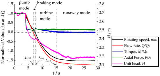
Figure 8. Time history curves of the key dynamic parameters of the pump during the runaway [35]. process.
The runaway process of a pump-turbine under pump conditions is a rapid transient process. In this process, the vibration of the unit, the fluctuation in the degree of water hammer, and the violent change in pressure pulsation endanger the pump-turbine unit [36]. To simulate the transient flow caused by a pump’s failure more effectively, M. Rohani et al. [37] proposed a point-implicit characteristic method (PIMOC) and improved pump formula. Xu Zhe et al. [38] studied the difference between the forward and reverse runaway transition processes of the bidirectional, low-lift, horizontal axial flow pump device and analyzed it with the entropy production theory. The results show that compared with the head loss obtained by an entropy generation calculation and a model test, the error is within 3% under both forward and reverse conditions, which verifies the accuracy of numerical simulation and entropy generation calculation. Li et al. [39] carried out an unsteady numerical simulation on the runaway conditions of a pump-turbine under different openings and compared it with the experimental results, obtaining the amplitude and frequency of the pressure pulsation. The results show that with the increase in the opening, the speed increases, and the amplitude of pressure pulsation also increases. The main frequency of pressure pulsation in the draft tube has transitivity and the amplitude increases with the flow direction. Using the steady calculation results of the initial working conditions as the initial flow field of an unsteady calculation, Zhou Daqing et al. [40] numerically simulated the power-off and runaway process of the axial flow pump device model and obtained the time required for the unit to reach the maximum speed of 20.35 s. At the same time, they revealed the variation law of the parameters such as the unit speed, flow rate, torque, and pressure corresponding to the measuring point with time and the transient process of the flow field of the meridian section of the flow channel of the device model and the pressure field of the impeller blade. He Zhongwei et al. [41] studied the power-off and runaway transition process of an axial-extension tubular pump device by considering the influence of the inlet and outlet boundary of the pressure along the water depth and the gravity term; analyzing the variation law of the flow rate, rotational speed, and pressure at different measuring points at different times; and comparing them with the real machine test. The results show that the maximum runaway speed is 36.98 s, and the maximum runaway speed is 30.97 rad/s, which is consistent with the experimental measurement.
Z Y Yang et al. [42,43] studied the variation of the pressure pulsation, runner coincidence, and guide vane torque during the runaway process of a pump turbine. Gou et al. [44] numerically simulated the runaway of the pump condition based on the VOF two-phase flow model and the single-phase flow model. It was found that the internal and external characteristics of the power station changed drastically and interacted with each other. The spiral vortex formed by the vortex in the runner in the draft tube is the main reason for the low-frequency pressure pulsation in the runaway condition. Dai et al. [45] analyzed the change in the external characteristic parameters and the evolution of the internal flow field in the runaway transition process of a vertical axial flow pump device and found that a highly spiraled vortex band appeared in the elbow channel during the runaway transition process. L et al. [46] studied and analyzed the pressure fluctuation and wake change of pump turbines during load rejection. Zhang Chenying et al. [47] used the SST turbulence model to simulate the unsteady runaway process of a centrifugal pump and analyzed the pressure fluctuation and vorticity by short-time Fourier transform (STFT) and vorticity intensity, respectively. The results show that when the high amplitude frequency of the pressure pulsation increases, a large area of vorticity appears in the elbow pipe. The main frequency of the pressure fluctuation at the elbow pipe is the blade-passing frequency (BPF). The main reason for the pressure fluctuation is the interaction between the rotor and the stator. X B Li et al. [48] numerically studied the dynamic flow characteristics of the runaway process and analyzed the time–frequency relationship of pressure pulsation by using a fast Fourier transform and a short-time Fourier transform. Time domain and frequency domain analyses are the main methods used to obtain change regulations. Dai Jing et al. [49] also studied the pressure fluctuation characteristics of axial flow pumps under different runaway conditions. The results show that the pressure fluctuation under runaway conditions is mainly affected by the rotating frequency, blade-passing frequency, and wake vortex frequency.
For the safety of the unit, pressure pulsation should be avoided [50]. During the shutdown process, if the gate is closed slowly, water backflow will also occur. If it is closed quickly, it will produce a huge impact force, damage the gate, or cause the pumping station to vibrate violently and produce a great deal of noise. Lu Weigang et al. [51] established a mathematical model of the falling motion of the fast gate based on relevant theories, where the closing time and impact speed can be obtained. Consequently, it was determined necessary to optimize the closing law of the gate. Wang et al. [25] optimized the two-stage closing law of the siphon axial flow pump unit gate and observed that the optimal closing process was 62.5% of the total stroke of the 10 s fast-closing and 37.5% of the remaining 90 s slow-closing processes. Of course, most scholars also adopt a uniform closing law. For the valve-locked pump device, the two-stage closing law [52,53,54,55] is mostly used, which can effectively reduce the incidence of the water hammer phenomenon during an accidental pump shutdown. In addition, the two sections of different pump stations’ fast-closing and slow-closing laws are different, and need to be optimized according to the actual situation.
Most of the numerical simulation studies on the shutdown process adopt the following ideas, as shown in Figure 9.
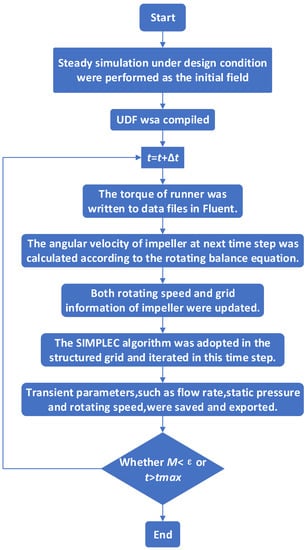
Figure 9. Algorithm routines of the runaway transient simulation [35].
Regarding a pump in the shutdown process, the unit torque equation is shown in Equations (1) and (2).
In the formula, is the rotational inertia of the unit; is the angular velocity during the unit-closing process; is the torque of the impeller subjected to water flow; is the mechanical loss for the unit; is the unit volume loss; is the time step.
4. Flap Gate
The flap gate is one of the ways used to cut off the flow in the operation of pumping stations [56,57], especially in low-lift pumping stations. The flap gate has different types, as shown in Figure 10. After the pump is started, the racket door is opened by the water flow impulse, which can also play the role of shunting in the start-up. After the shutdown, with the decrease in the impact force of the water flow, the flap door falls due to its weight. After the pump is turned to the positive flow, it closes and presses the flow channel in the backflow stage, which plays a role in stopping the flow. Compared with other flow cut-off methods, the flap gate has the advantages of a simple structure, easy-sealing properties, and convenient use, but there are also some shortcomings. For example, in the process of opening, hydraulic loss is caused by the small opening angle. If the flap gate is added to the gate, the situation is better. After the gate is opened, the flap gate does not work; additionally, in the process of a shutdown, the pat door under the weight and water pressure closed will produce a larger impact force on the pat door itself or the hydraulic structures will produce certain harm [58]. In recent years, scholars have conducted some research on the impact of the door [59,60,61,62,63]. We should choose the appropriate door type, structure, and [64,65] corresponding auxiliary system [66,67] to achieve the most effective effect.
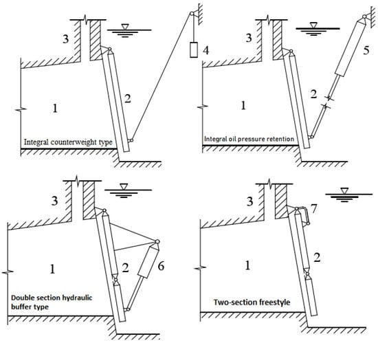
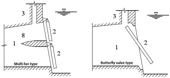
Figure 10. Diagram of flap valve types [68]. 1—Outlet channel, 2—Flap valve, 3—Vent, 4—Counterweight, 5—Buffer cylinder, 6—Buffer water cylinder, 7—Rocker arm hinge link, and 8—Diaphragm pier.
5. Transition Process Accident
The water hammer of a pumping station has a great influence on the normal operation of the pumping station project. Many pumping stations have suffered serious damage due to water hammer. For example, in 1981, a serious explosion occurred in a petrochemical plant due to water hammer. The reason was that the workers erroneously operated the valve. The water hammer pressure destroyed the water pipeline, resulting in the shutdown of several satellite plants in the plant and serious losses. In 1983, due to maintenance negligence, grinding occurred after a water plant in Beijing had installed a pump outlet check valve shaft, wherein the valve disc suddenly fell off, rushed to the valve body contraction outlet, and suddenly blocked the outlet, resulting in a great degree of water hammer. Huge water columns and blown-up lids rushed toward the roof of the multi-meter-high factory building, which was flooded by 10 pumps in half an hour, causing a great impact and the loss of production and life. On 8 July 1985, when the No.2, No.3, and No.4 pump units were running at the same time in Changsha No.5 Waterworks, the power grid was suddenly cut off, and the automatic pressure-holding hydraulic butterfly valve of the three units was closed at the same time. When water hammer was generated, the hydraulic butterfly valve’s body and the valve foundation of unit No.3 were damaged, and a large shutdown event occurred due to flooding [69]. On 17 September 2005, in Yinqian District Thermal Power Engineering’s circulating water pump rooms #1 and #5, the check valve could not achieve slow closure during the circulating pump’s stop process due to pump water hammer and suffered serious damage, specifically, (1) pump foundation cracks, (2) the coupling incurred 3 mm and 8 mm misalignments, and (3) the elastic washer was seriously worn [70]. Around 9:00 on 2 June 2010, the new drainage system in Hejiayan Gold Mine was tested to simulate the sudden interruption of power during the commissioning process. At the moment of power failure, with a loud bang, the stainless-steel buffer at the outlet of the D280 multi-stage pump was seriously pulled up, forming a twist, and a drainage pipeline with a diameter of 273 mm suffered obvious displacement. Multiple welds ruptured, the pump impeller reversed at high speed, and the check valve spool at the pump outlet ruptured. Fortunately, no casualties or flooding accidents occurred. The reason for this pump-stopping water hammer accident was that the ordinary check valve installed at the outlet of the pump did not meet the requirements of the drainage system in terms of pressure strength and structure. Second, the drainage pipeline was not fixed firmly, which is very conducive to pipeline displacement [71]. The pressurized pump station in the water source area of Baotou Steel adopted a horizontal centrifugal pump. In 2000, the pump was started after the preparation of unit #3 before. After the unit started, after about 15 s, water hammer occurred, the cover plate of the outlet pipe trench was lifted, and a large amount of water gushed out. It was judged that the outlet pipe had burst; thus, the suction gate was closed urgently, and all the pumps were stopped. Due to the large amount of water that had discharged from the accident point, when the suction gate was closed halfway, the water in the pump room had risen to the chest of the operator, the personnel were forced to evacuate, and the pump room was flooded. After an analysis, it was determined that the gas in the pipeline had not been exhausted, and the pressurized water valve was opened too fast, so when the pump was started, the pressure and pump speed changed, and the flow rate in the pipeline was greatly increased. At this point, high-pressure water flow—a pressure of 0.9 MPa—was present in the main pipe, and the two water flows acted on the air mass at the same time. With the increase in the compressed air mass, the air mass eventually collapsed, and the two water columns collided with each other, resulting in instantaneous pressure changes, and causing the pipeline to vibrate and form a pump-starting water hammer. The weak links in the pipeline were damaged under the action of pressure from the water hammer [72].
Water hammer accidents often occur in foreign nuclear power plants. In the United States alone, 76 water hammer accidents were reported from 1965 to 1981. In 1985, a huge water hammer hazard occurred in unit #1 of the San Oro Fell Nuclear Power Plant in California, the United States. The accident was due to an electric short circuit that caused the main feed water pump in the secondary circuit to stop the pump and cut off the flow of water. Four minutes later, the operating workers mistakenly operated and started the make-up pump, resulting in a catastrophic water hammer accident. More than 50 m of water supply pipeline incurred seriously distorted displacement, more than a dozen supports were destroyed, displacement of 30 cm was measured, and there was a burst pipe with 2 m long fish mouth cracks; thus, the nuclear power plant was forced to shut down [73]. It is also the effect of water hammer on the pumping station project, which causes serious damage to the pump station hydraulic transition process, that has attracted a great deal of research attention.
This entry is adapted from the peer-reviewed paper 10.3390/en15228338
This entry is offline, you can click here to edit this entry!