Heat Management Strategies for an Induction Motor: History
Please note this is an old version of this entry, which may differ significantly from the current revision.
Contributor: , , ,

Induction motors have gained a renewed interest due to this new shift from conventional power sources to electric power. These motors are known for their high commencing torque, adequate speed control, and reasonable overload capacity. However, induction motors have an innate thermal issue wherein their lifespan and performance are strongly temperature dependent. Hence, it is highly essential to focus on the thermal management aspect of these motors to ensure reliability and enhance performance. This research suggests an integrated approach with two or more cooling strategies and help to serve members of the scientific community, manufacturers or motors users who are interested in the thermal management of induction motors

  • lumped parameter thermal networks
  • computational fluid dynamics
  • thermal analysis
  • thermal management

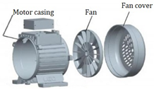
1. Air Cooling Approach

Roffi et al. [1] compared many cooling strategies involving various designs in the fan, which includes the likes of standard centrifugal fans and some axial fans for the same base fan cover. The experimentation was conducted with an IE3 class 7.5 kW, 4 poles, 400 V squirrel caged IM at no and part loads. Table 1 provides the simulated outcomes for four dissimilar axial fan designs and Table 2 gives the experiment results of part load for the IM with four different cooling fan systems. Table 3 shows the respective fan and cover designs for Table 1 and Table 2. The inclusive efficacy improves unidirectional self-ventilated motors when fan power is reduced without changing the velocity of the air and the volumetric airflow. Henceforth, not affecting the motor operating temperatures.
Table 2. Part-load experimental results with four different cooling fan systems [1].
Various Fan Designs and Covers Performance of Fan at 1483 rpm Performance of Motor at 58.08% Load
  Vair (m/s) Pfan (W) Ploss,total (W) Efficiency (%) ΔƟframe (K)
Centrifugal Original Cover, small 4.4 7 606 87.8 19
Centrifugal Original Cover, large 7.0 16 615 87.6 18
Axial design, C, Original Cover 5.1 7 600 87.9 18
Axial design, C, Customized Cover 5.4 9 604 87.8 17
Table 3. Fan designs and the respective cover [1].
S.No Fan Type Fan Configuration Original Cover Performance
1 Small Centrifugal Energies 15 08127 i001 Energies 15 08127 i002 
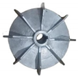
Applicable for the smaller motor cooling approaches. Efficient cooling for the rotor
2 Large Centrifugal Energies 15 08127 i003 Energies 15 08127 i004 
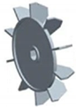
Applicable for the bigger motor cooling approaches. Efficient cooling for the rotor
3 Axial Design, A Energies 15 08127 i005 Energies 15 08127 i006 Applicable for the moderate motor cooling approaches. Efficient cooling for the rotor, compared to centrifugal type
4 Axial Design, B Energies 15 08127 i007 Energies 15 08127 i008 Applicable for the moderate to heavy motor cooling approaches. Efficient cooling for the rotor, compared to Axial design (A)
5 Axial Design, C Energies 15 08127 i009 Energies 15 08127 i010 Applicable for the moderate to heavy motor cooling approaches. Efficient cooling for the rotor, compared to all the available designs

Moon et al. [2] numerically studied the characteristics of the thermal flow of an enclosed fan-cooled IM. The various configurations, including the fin, which is joined to the surface of the frame, frames embedded with air channels, air duct through the rotor core and fan cover, which enclosed the external fan, were incorporated and variations among them were studied. CFD analyses were performed and results were validated for accuracy through experimental tests, Figure 1. Based on the parametric studies, the level of cooling effect was raised to its maximum power density, and, as a result, the motor was developed: 2350 kW, 560 frames, 4 poles, 6 kV and 60 Hz.
Figure 1. Results of increase in stator winding temperature [2].
Kim et al. [3] have studied the effects of air gap fans and the cooling of the winding of a large capacity IM using computational thermal coupled analysis to improve the accuracy of results. In this work, varying iron loss distribution model that considered the time and rotation period was included, Figure 2. The performance of different configurations with only front air gap fan, only rear-end air gap fan, and when both the sides had the air gap fan were compared to a scenario with no air gap fans. Results showed that the effect of vanishing stagnant flow near the gaps was due to the fact that the fan increases the flow rate distribution, Table 4. The average temperature in the IM declines with the growth in the average flow velocity in the cavity. This also led to the heat transfer coefficient increase by 31% at the surfaces of the windings and the air gaps by 90%. For a singular fan scenario, the fan at the rear end had improved by 36%, and in the case of the fan at the front end, this was only 35%.
Figure 2. Schematic diagram of an IM with air gap fan [3].
Table 4. Temperature distribution (a) without a fan; (b) with fan [3].
Ansys Simulated Sections of the Motor Simulated Temperature, °C
(With Out Fan)
Simulated Temperature, °C
(With Both Fans)
% of Temperature Reduction Due to Fans Both the Sides
Rotor core section
(central section)
324 233 28
Rotor core section
(ends section)
235 202 14
Air gap between rotor and stator 172 162 5.8
Stator core 152 112 23
Housing 62 52 16
Air flow passage 32 22 31
Zhang et al. [4] have studied temperature profile over air-cooled asynchronous IM by coupled field FEM approach. A fluid model was suggested, where all rotor parts are considered fluids with certain conditions. Due to the rotation of the rotor, Coriolis force and centrifugal forces are taken into account, since they have a huge influence. A new asynchronous motor is designed with a 6-phase, 8-poles and 200 kW capacity to validate the proposed methodology. The multi-fluid model showed positive agreement with the simulated and experimental results.
Kim et al. [5] to improve the existing thermal circuit’s model introduced a new thermal model (TNM) by compensating for the modelling of the heat transport by airflow. Thermal analysis was performed on an open-type air-cooled IM. A total number of 36 nodes for solid and fluid regions in the motor were chosen to build the thermal nexus model. In comparison to CFD and the experimental method, the thermal nexus model was able to show a 4% less error. Further, the cooling path analysis showed a 3% less error, compared to CFD. It was, hence, concluded that the developed model was handy in improving the design of the motor cooling system.
Hashish et al. [6] patented a new invention of an auxiliary cooling system for TEFC IM. The invention provided a buffet thermal shroud that was incorporated over the present motor housing cooling fins in a spaced manner. The tabs were aligned in the airflow channel amid the contrasting cooling fins, where they are in thermal and fluid communications with the cooling air-flow. The turbulence created in the cooling air-flow by the tabs or shroud fingers were able to increase convective heat transfer efficiency and contact time amid the cooling air and motor cooling fins. It was further stated that the present invention can be retrofitted on any IM quickly at the lowest possible cost and with relatively little effort.

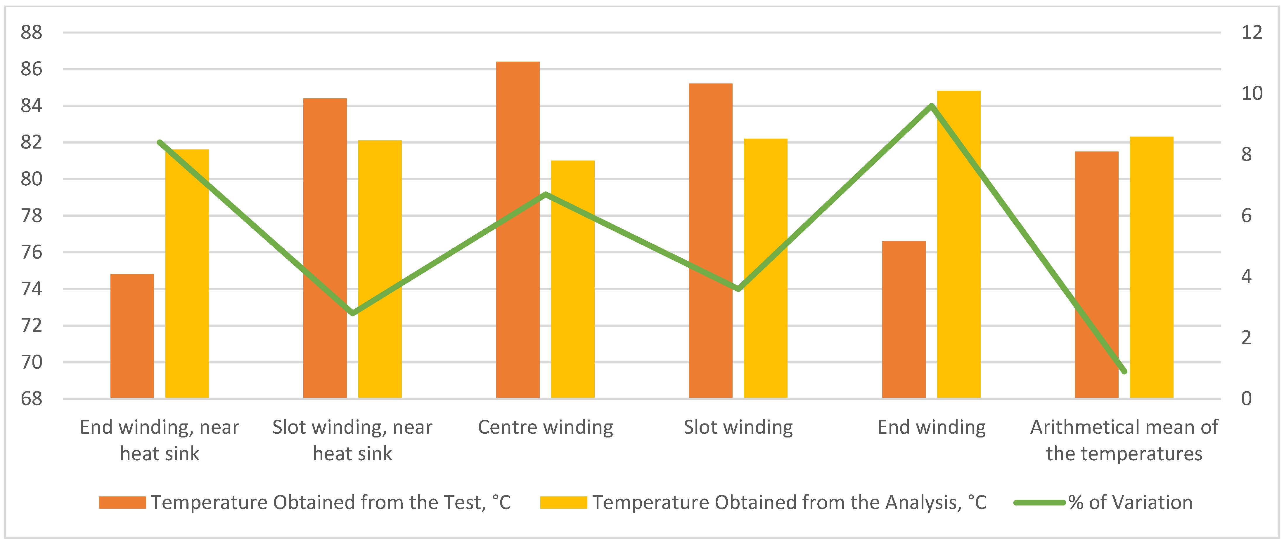
2. Liquid Cooling Approach

Rehman et al. [7] conducted the 3D steady-state model investigation of a 90 kW IM with three different layouts of cooling jackets and four types of coolant flow passes. Four different water flows (5, 10, 20 and 30 LPM) were numerically studied. Maximum functioning temperature and pumping power were the key areas of focus in this investigation. The different configurations are shown in Figure 3 and Figure 4. The upper limit of the operating temperature for the design of the cooling jacket was set at 373 K. The highest temperature was observed to be in the stator winding due to intense heat loss from the winding loss. It was observed that the more the number of passes, the less the maximum temperature reached. Furthermore, the effect of varying the number of passes becomes less on increasing the passes beyond six, Table 5 and Table 6.
Figure 3. Cooling jacket configuration with different number of passes [7].
Figure 4. Port configuration [7].
Table 6. Rate of temperature variation, with respect to the number of passes and coolant flow rate [7].
Number Coolant Passes Temperature, °C
with 2 Ports
30 lpm to 10 lpm
Temperature, °C
with 3 Ports
30 lpm to 10 lpm
Temperature, °C
with 3 Ports (Centre Inlet)
30 lpm to 10 lpm
Average % of the Variation in Temperature for 30 lpm
4 365–380 375–395 370–395 1.3
6 360–375 370–385 375–395 4.1
8 360–375 360–375 360–375 0
10 360–375 360–375 360–375 0
  Average % of variation > 4 Average % of variation > 4 Average % of variation > 5  
Han et al. [8] carried out the analysis of a high-speed water-cooled IM using LPTN methods. The heat transfer coefficients of the water jackets channel and interface amid the core of the stator and frame were an influential factor, since the motor was a water-cooled type. Further, from Table 7 it was observed that the temperature of the trailing part of the end winding was greater, in contrast to the front part, since it had a minute gap with the housing. The authors concluded by stating that if the important parameters, such as interface gap and heat conductivity of the materials are properly selected, accurate distribution of temperature can be achieved from the LPTN method.
Table 7. Temperature distribution [8].
Evaluation Method IM Winding, °C IM Rotor, °C Remarks
  End Part In Slot End Part Core Shaft  
Analysis 71.3 66.5 76.3 172.3 166 considering FEM losses
Analysis 77.7 72.2 83.3 185.3 179 considering test losses
Test 75.2 65.5 80.4 - - -
Satrústegui et al. [9] presented a thermal model of an IC71 IM with different design criteria for the water-cooled system. The key parameters that describe the water jacket and shaft were identified through the use of a validated thermal model and CFD simulation. The topology of the water jacket was analyzed and it was observed that with similar cooling areas, Figure 5. The topologies were classified based on the pressure drop introduced in the cooling system. Spiral water jackets were chosen as the preferred option for reducing the pressure drop but were the most complex to manufacture. Later, two parameters that had almost no influence were determined, which were the interspace of cooling ducts and the distance between the ducts and the stator stack. Finally, the influence of water in these cooling arrangements was analyzed using CFD techniques. The temperature of some parts of the motor reduced significantly due to the enhanced coefficient of heat transfer by the use of water.
Figure 5. (a) Spiral water jacket; (b) Bifurcated U-shaped water jacket; (c) Axial water jacket; (d) Dial water jacket [10][11].
Tanguy et al. [12] performed an experimental study on the oil cooling system for an electric motor. The focus of the study was to determine the influence of the oil temperature, rotation speed and oil flow rate on the cooling of the stator coil end cooling. The oil flow rate was changed between 40 and 360 L/h, the oil temperature between 50 °C to 75 °C and the speed between 0 to 4600 rpm. Different injection patterns, see Figure 6, were utilized to study the above factors, which have been summarized in Figure 7.
Figure 6. Different oil flow patterns: (a) Flat jet nozzle (FJN); (b) Full cone nozzle (FCN); (c) Dripping nozzle; (d) MultiJet nozzle [10].
Figure 7. Experimental testing conditions [12].
The author concluded that oil, even in restricted amounts, had greatly improved the global heat transfer, in contrast to air-based cooling only. The dripping injector proved to be highly effective as the oil is injected with a higher flow rate at the top region and the end windings. This is followed by nozzle injection in which the efficiency was similar for both types of nozzles. The jet seemed to be ineffective in the cooling performance. The oil flow rate remained the major factor in improving global efficacy for any configuration, Figure 6.
Rippel [13] patented a new method of a liquid cooling system called transverse lamination cooling wherein the coolant flows transversely through a narrow region formed by apertures in every other magnetic lamination. The new invention greatly improved the cooling performance of the stator winding, as well as the rotor winding.
Recent advancements in the field of dimple cooling geometry have opened new opportunities for the utilization of such geometries in liquid-cooled induction motors. Qian et al. [14] conducted the numerical simulation of both simple dimples with dissimilar geometries and the complete dimple jacketed heat exchanger with diverse dimple measures. It was observed that the dimples could enhance the heat transfer efficiency in contrast to the conventional jacketed heat exchanger. Pan et al. [15] aimed to study the numerical analysis and comparison of fluid flow and heat transfer characteristics of a microchannel heat exchanger with diverse re-entrant cavities. It was concluded that the heat transfer efficacy of microchannel heat exchangers with re-entrant cavities is improved, and the pressure drop is lower. The highest heat transfer efficacy comes from a microchannel heat exchanger with trapezoidal-shaped cavities, whereas the smallest pressure drop comes from a microchannel heat exchanger with fan-shaped cavities. Fazli et al. [16] aimed to expect the turbulent flow and heat transfer through diverse channels with periodic dimple walls. The efficacy of several low-Re k-turbulence models in predicting local heat transfer coefficient is assessed more explicitly. The nonlinear k-ε model forecasts a bigger whirly bubble inside the dimple with more impingement and upward flow than the zonal and linear k-ε models, according to the numerical predictions. Heat transport estimates inside the dimples and their rear rim improve when the linear k-ε model is used. The nonlinear k-ε function, on the other hand, yields the most accurate thermal forecasts.
Apart from the cooling structures, there also has been developed in the field of cooling fluids apart from the conventional water and oil. Deriszadeh et al. [17] investigate the possibility of directly cooling traction motors in the car industry using a liquid medium. As a coolant, a mixture of ethylene glycol and water with different volume fractions is utilized. Thermal analyses of the cooling system are carried out using CFD and 3D turbulent fluid motion analysis. During research and modelling, it was discovered that increasing the number of fluids turning channels, the volume combination of ethylene glycol, and the Reynolds number increases the heat transfer coefficient. When the number of rotations was eight, the volume mixing ratio of ethylene glycol to water was 60:40 and Reynolds no. 5000, the highest performance was recorded. Ijaz et al. [18] carried out research comprising a simulation-based evaluation of graphene-doped nano-coolant thermal properties in an automobile radiator. To explore the impact of graphene oxide (GO) nanoparticles doped in a base fluid (water) as a nano coolant for a car radiator’s temperature reduction over the tube length and efficacy. As the concentration of GO nanoparticles by volume increases, a significant temperature reduction is observed. Temperature drops of 9.68 K, 10.89 K and 11.9 K are typical for 6%, 8% and 10% of the GO nanoparticles, respectively. The efficacy of the radiator rises in proportion to the percentage increase in nanoparticle addition. Mukherjee et al. [19] studied the value of k of commercial engine coolant-based SiO2 nanofluids utilizing a unique sonic velocity measuring methodology. This was performed, considering k is a vital constraint to define the heat transfer efficacy. Nanofluids were made by dispersing SiO2 nanoparticles in engine coolant at five distinct mass concentrations: 0.01%, 0.05%, 0.10%, 0.50% and 1%. The temperature rise was more effective than the rise in nanofluid concentration, according to these findings. At 65 °C, a nano-coolant concentration of 1% demonstrated a maximum increase in k of 21.083%. Ultimately, in this work, a novel mathematical correlation was created to accurately estimate the value of k of engine coolant-based SiO2 nanofluids.

3. Heat Pipes/Plates Cooling Approach

N. Putra et al. [20] explored on the heat management of electric motors using L-shaped heat pipes. The heat pipes were located on the surface of the motor housing, Figure 8. The L-shaped flat heat pipes with 154 mm evaporator section and 34 mm condenser section with heat sinks were made of copper tubes. The heat sinks were used to enable fast heat transfer to the surrounding area. For uniform heat generation, a cartridge heater was positioned inside the motor housing. The heat generation process was regulated by an AC voltage regulator. The experiment was conducted for five sets of heat loads, namely 30 W, 60 W, 90 W, 120 W and 150 W. Further, the experiment was conducted without the L-shaped flat heat pipes to increase or decrease in performance. The results indicated that on using the L-shaped heat pipes, the temperature of both the inner and outer surface reduced to a greater, Table 8. For instance, at a heat load of 150 W, the utilization of the L-shaped flat heat pipes reduced the inner and outer surface temperature by 34.6 °C and 33.8 °C correspondingly, as compared to without the heat pipes. To achieve a high motor performance and high power density, various effective cooling schemes have to be incorporated. Cooling schemes aiming to bring down the temperatures at the hot spots and raise motor thermal efficiency have to be carefully adopted. Hence, an IM system with novel motor topologies, geometrical parameters, design and materials would greatly affect the electrical/electromagnetic performance of the system, Figure 9. Out of all the cooling schemes, air-cooling is the cheapest. Liquid cooling is a very effective strategy but complex geometry, pumping and also the addition of nanoparticles makes it more expensive, compared to all the cooling schemes. Heat pipe cooling is effective for motor housing cooling but compared to liquid cooling it is cheaper because this scheme is mostly an add-on to the existing air cooling strategy.
Figure 8. Schematic of L-shaped flat heat pipes mounted on an electric motor model [21].
Figure 9. Cooling schemes for the components of heat sources [3][5][6][7][9][12][13][14][15][16][17][18][19][20][21][22][23][24][25].
Table 8. Effect of heat pipe implementation [20].
Given Heat LOAD, W Outer Surface Temperature, °C (with Out Heat Pipes) Outer Surface Temperature, °C (With Heat Pipes) % of Variation (Temperature Reduction) Inner Surface Temperature, °C (with Out Heat Pipes) Inner Surface Temperature, °C (With Heat Pipes) % of Variation (Temperature Reduction)
31 42 35 20 48 40 20
61 58 42 38 70 54 29.6
91 75 52 39 90 68 32.3
119 88 58 51 110 78 41
149 100 64 56 128 90 42.2

This entry is adapted from the peer-reviewed paper 10.3390/en15218127

References

  1. Roffi, M.; Ferreira, F.J.; De Almeida, A.T. Comparison of different cooling fan designs for electric motors. In Proceedings of the 2017 IEEE International Electric Machines and Drives Conference (IEMDC), Miami, FL, USA, 21–24 May 2017; IEEE: New York, NY, USA; pp. 1–7.
  2. Moon, S.H.; Jung, Y.H.; Kim, K.W. Numerical investigation on thermal-flow characteristics of a totally enclosed fan cooled IM. In Proceedings of the 2016 XXII International Conference on Electrical Machines (ICEM), Lausanne, Switzerland, 1–4 September 2016; IEEE: New York, NY, USA; pp. 1928–1933.
  3. Kim, C.; Lee, K.S.; Yook, S.J. Effect of air-gap fans on the cooling of windings in a large-capacity, high-speed IM. Appl. Therm. Eng. 2016, 100, 658–667.
  4. Zhang, Y.; Ruan, J.; Huang, T.; Yang, X.; Zhu, H.; Yang, G. Calculation of temperature rise in air-cooled IMs through 3-D coupled electromagnetic fluid-dynamical and thermal finite-element analysis. IEEE Trans. Magn. 2012, 48, 1047–1050.
  5. Kim, C.; Lee, K.S. Thermal nexus model for the thermal characteristic analysis of an open-type air-cooled IM. Appl. Therm. Eng. 2017, 112, 1108–1116.
  6. Hashish, E. IM Auxiliary Cooling System. United States Patent US 8,912,695, 16 December 2014.
  7. Rehman, Z.; Seong, K. Three-D numerical thermal analysis of electric motor with cooling jacket. Energies 2018, 11, 92.
  8. Han, P.W.; Choi, J.H.; Kim, D.J.; Chun, Y.D.; Bang, D.J. Thermal analysis of high-speed IM by using lumped-circuit parameters. J. Electr. Eng. Technol. 2015, 10, 2040–2045.
  9. Satrústegui, M.; Martinez-Iturralde, M.; Ramos, J.C.; Gonzalez, P.; Astarbe, G.; Elosegui, I. Design criteria for water cooled systems of induction machines. Appl. Therm. Eng. 2017, 114, 1018–1028.
  10. Le, W.; Lin, M.; Lin, K.; Liu, K.; Jia, L.; Yang, A.; Wang, S. A Novel Stator Cooling Structure for Yokeless and Segmented Armature Axial Flux Machine with Heat Pipe. Energies 2021, 14, 5717.
  11. Wu, S.; Zhou, J.; Zhang, X.; Yu, J. Design and Research on High Power Density Motor of Integrated Motor Drive System for Electric Vehicles. Energies 2022, 15, 3542.
  12. Davin, T.; Pellé, J.; Harmand, S.; Yu, R. Experimental study of oil cooling systems for electric motors. Appl. Therm. Eng. 2015, 75, 1–13.
  13. Rippel, W.E.; Rippel, E.E. Im with Transverse Liquid-Cooled Rotor and Stator. United States Patent US 9,985,500, 29 May 2018.
  14. Qian, J.Y.; Wu, Z.; Zhang, Q.K.; Jin, Z.J.; Sunden, B.A. Heat transfer analysis on dimple geometries and arrangements in dimple jacketed heat exchanger. Int. J. Numer. Methods Heat Fluid Flow 2019, 29, 2775–2791.
  15. Pan, M.; Wang, H.; Zhong, Y.; Fang, T.; Zhong, X. Numerical simulation of the fluid flow and heat transfer characteristics of microchannel heat exchangers with different reentrant cavities. Int. J. Numer. Methods Heat Fluid Flow 2019, 29, 4334–4348.
  16. Fazli, M.; Raisee, M. Computation of flow and heat transfer through channels with periodic dimple/protrusion walls using low-Reynolds number turbulence models. Int. J. Numer. Methods Heat Fluid Flow 2019, 29, 1178–1207.
  17. Deriszadeh, A.; de Monte, F.; Villani, M.; Di Leonardo, L. Hydrothermal Performance of Ethylene Glycol and Water Mixture in a Spiral Channel for Electric Motor Cooling. In Proceedings of the 2019 21st European Conference on Power Electronics and Applications (EPE’19 ECCE), Genova, Italy, 3–5 September 2019.
  18. Ijaz, H.; Raza, H.; Gohar, G.A.; Ullah, S.; Akhtar, A.; Imran, M. Effect of graphene oxide doped nano coolant on temperature drop across the tube length and effectiveness of car radiator–A CFD study. Therm. Sci. Eng. Progress 2020, 20, 100689.
  19. Mukherjee, S.; Halder, T.; Ranjan, S.; Bose, K.; Mishra, P.C.; Chakrabarty, S. Effects of SiO2 nanoparticles addition on performance of commercial engine coolant: Experimental investigation and empirical correlation. Energy 2021, 230, 120913.
  20. Putra, N.; Ariantara, B. Electric motor thermal management system using L-shaped flat heat pipes. Appl. Therm. Eng. 2017, 126, 1156–1163.
  21. Gundabattini, E.; Mystkowski, A.; Idzkowski, A.; R., R.S.; Solomon, D.G. Thermal Mapping of a High-Speed Electric Motor Used for Traction Applications and Analysis of Various Cooling Methods—A Review. Energies 2021, 14, 1472.
  22. Gundabattini, E.; Mystkowski, A. Review of air-cooling strategies, combinations and thermal analysis (experimental and analytical) of a permanent magnet synchronous motor. Proc. Inst. Mech. Eng. Part C J. Mech. Eng. Sci. 2022, 236, 655–668.
  23. Solomon, D.G.; Greco, A.; Masselli, C.; Gundabattini, E.; Rassiah, R.S.; Kuppan, R. A review on methods to reduce weight and to increase efficiency of electric motors using lightweight materials, novel manufacturing processes, magnetic materials and cooling methods. Ann. De Chim.-Sci. Des Matériaux 2020, 44, 1–14.
  24. Gundabattini, E.; Mystkowski, A.; Raja Singh, R.; Gnanaraj, S.D. Water cooling, PSG, PCM, Cryogenic cooling strategies and thermal analysis (experimental and analytical) of a Permanent Magnet Synchronous Motor: A review. Sādhanā 2021, 46, 3.
  25. Boopathi, N.G.; Muthuraman, M.S.; Palka, R.; Wardach, M.; Prajzendanc, P.; Gundabattini, E.; Rassiah, R.S.; Solomon, D.G. Modeling and Simulation of Electric Motors Using Lightweight Materials. Energies 2022, 15, 5183.
More
This entry is offline, you can click here to edit this entry!
Video Production Service