1. Materials
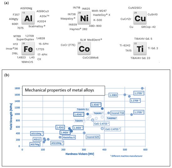
Additive manufacturing in the form of 3D metal printing offers the possibility to use a wide range of metal alloys and allows for the production of the desired materials to achieve the wanted part properties. The different materials are displayed in
Figure 7a.
Figure 7b shows the mechanical properties of the various materials’ processing. These values are comparable, for example, to the properties of castings. The nomenclature in
Figure 7b refers to either the chemical composition of alloys such as AlSi10Mg or the material number according to DIN [
40,
41,
42,
43].
Figure 7. (
a) Available metal powders [
40]; (
b) mechanical properties of metal alloys (AM powder) [
27].
2. AM According to a Drivetrain Hybrid/Battery Electric Vehicle
Due to the steadily increasing vehicle weight resulting from electrification and the associated deterioration in driving dynamics, it is of great interest to integrate lightweight construction approaches and innovative highly efficient components into the vehicle [
44,
45,
46].
A drivetrain for battery-electric and hybrid drive topologies can be divided into three component categories with regard to additive manufacturing, as already described in detail in
Section 2:
Intersections in the categories and combined total solutions are also possible.
3. Functional and Thermally Stressed Components for Electrical Machines
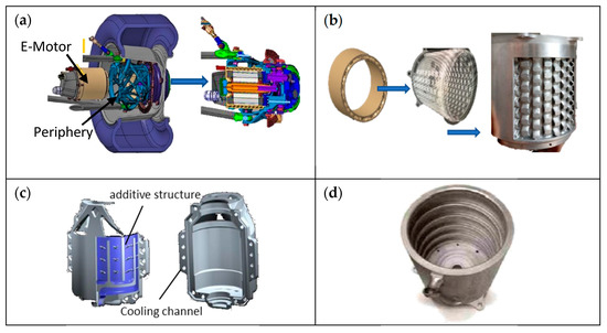
Examples of machine housing for applications involving electric vehicles (EVs) are shown in Figure 8. Hardware- and software-based CAD models are displayed there. In these four cases, a special integrated cooling channel or geometry is designed for liquid cooling directly into the housing to improve efficiency and enhance the overall functionality in terms of thermal management.
Figure 8. (
a) Electrical motor mounted in wheel hub; (
b) electrical motor housing with integrated cooling [
47,
48]; (
c) housing with integrated cooling [
49]; (
d) housing with helix structured cooling channels [
50].
The housing shown in
Figure 8a was redesigned to be manufactured with AM in AlSi10Mg because of the critical temperature conditions under which the original motor had to operate. As shown in
Figure 8b, AM allowed for a complex design for integrated cooling. The redesigned cooling geometry resulted in better heat dissipation, and weight and operating-pressure reduction. This increased the overall heat conduction and efficiency of the cooling system by nearly 20%. In addition, increased temperatures at peak loads during operation are quickly cooled down [
47,
48].
Figure 8c also shows another CAD option of integrated cooling [
49].
Figure 8d shows an electric motor with a helix cooling channel inside, realised as a single component. The application in practice shows that the cooling capacity can be increased by up to 37%, while the weight is reduced by 16% [
50].
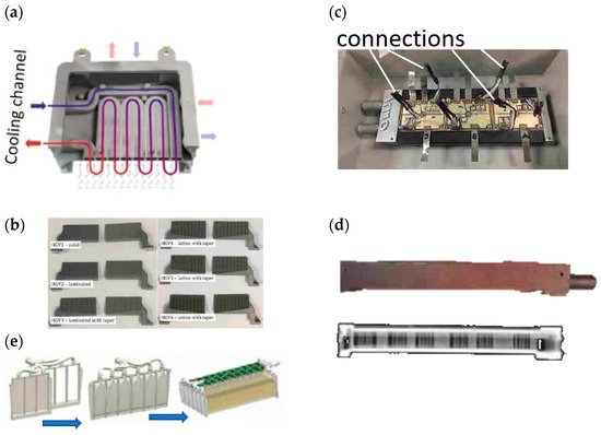
Another example is different kinds of housings or cooling systems, presented in
Figure 9. AM was successfully used to manufacture housing from a single component with a functionally integrated cooling channel and additional connection points; see
Figure 9a. The housing protects the power electronics during operation and assembly. Furthermore, approaches regarding modularity can more easily be implemented [
51].
Figure 9. (
a) Multifunctional housing for power electronics [
51] (
b); heat guides for an electrical machine [
52]; (
c) inverter with cooling plate; (
d) X-ray view cooling plate [
53]; (
e) battery cooling system [
54].
In [
52], the authors investigated AM heat guides (HGs) produced from AlSi10Mg that are mounted between windings in an actively cooled stator. The study showed that HGs could be fabricated using AM, and their complex geometry had reduced mass, low power dissipation, and good thermal conductivity. The initial results using FEM temperature analysis showed better handling of the input power by 40% in low-frequency operation, and an improvement of 20% in high-frequency operation. Theoretically obtained data were experimentally validated and showed good correlation with the theoretical measurements. During the measurements, the components had comparatively high electrical resistance, but this could be neglected in terms of heat dissipation. In general, this improved the thermal conductivity between winding and stator by 55–85%.
An inverter’s cooling system, shown in
Figure 9c, was fabricated from the aluminium alloy AlSi10Mg using AM and then examined.
Figure 9d shows the inverter and heat sink with an X-ray image to illustrate the internal geometry. The result was the 99% efficiency of the inverter under several operating conditions. Moreover, an increase in power density was possible [
53].
The optimised additively manufactured battery cooling components shown in
Figure 9e enable the maximal usable power to be used up at any time during operation. In addition, the battery can be preheated to 45 °C before start-up. The cooling components had a total weight of 225 g [
54].
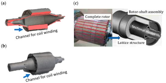
A lightweight rotor design approach is also helpful in further reducing and optimising the mass of an electric machine, as illustrated in
Figure 10 with two examples. By using AM, the rotor displayed in
Figure 10a could be built according to a lightweight design concept, as can be seen from the sectional view of the CAD model. Furthermore, the efficiency of the rotor could be enhanced and validated through the experimental investigations on the physical model shown in
Figure 10b [
55,
56,
57,
58].
Figure 10c successfully demonstrates how a rotor could be realised by using lattice structures due to an efficient lightweight construction approach. Tool steel (H13) was used for the rotor itself. Although the magnetic properties of the tool steel (H13) are relatively poor, the properties of existing soft magnetic composites (SMCs) were achieved with heat treatment. Compared to a conventionally manufactured component, the total mass of the rotor was reduced by 25%, thereby reducing the moment of inertia by 23% [
59].
Figure 10. (
a) Sectional rotor view; (
b) 3D-printed functional model [
55,
56,
57,
58]; (
c) rotor with lattice structure [
59,
60].
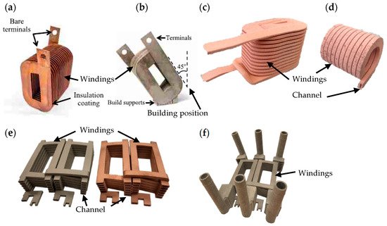
Following the presentation of housing and attachments, windings are one of the most important components of an electric motor, which are usually produced from copper due to its relatively high electrical conductivity. The fact that some parameters in the winding production and design complicate the manufacturing process, AM allows for new design approaches, and improves the performance and manufacturability compared to conventional methods of design and manufacture [
61]. As shown in
Figure 11, additive manufacturing allows for improving the power density of motors through the special arrangements of the windings and hairpin manufacturing. The motors can be smaller and lighter due to the windings, which saves space and weight [
61,
62]. The better internal cooling of the motors directly in the winding can also be realised. For the windings shown in
Figure 11a, the priority was to exploit the geometric design latitude associated with AM and thus reduce ac loss. In this way, it was possible to develop an optimised geometry that minimises losses and significantly reduces the component size. In addition, further studies were published in which the systematic redesign in the form of a highly concentrated winding topology was demonstrated. This resulted in a significant loss reduction of 40% at a hot spot temperature of 145 °C compared to the pervious iteration.
Figure 11. (
a) AM-shaped profile windings; (
b) self-supporting AlSiMg alloy sample [
63,
64,
65]; (
c) 3D-printed copper coil; (
d) hollow core design [
66] (
e); AlSi10Mg and CuCr1Zr coil samples (
f); coils with heat exchangers [
67,
68,
69,
70,
71].
Additive manufacturing allows for improving the power density of the motors through special arrangements of the windings and hairpin manufacturing. The motors can be smaller and lighter due to the windings, which saves space and weight [
61,
62]. The better internal cooling of the motors directly in the winding can also be realised. For the windings shown in
Figure 11a,b, the priority was to exploit the geometric design latitude associated with AM, and thus reduce AC loss. In this way, it was possible to develop an optimised geometry that minimises losses and significantly reduces the component size. In addition, further studies were published in which systematic redesign in the form of a highly concentrated winding topology was demonstrated. This resulted in a significant loss reduction of 40% at a hot-spot temperature of 145 °C compared to the previous iteration [
63,
64,
65].
Figure 11c,b show that the hollow demonstration windings had the highest conductivity with a resistance of 3.19 µΩ-cm (54% IACS). Due to the discrepancies between the CAD values and the real available parts, it was difficult to determine the exact cross-sectional geometry for resistivity calculation. Furthermore, it could be verified that the material used (pure copper) has enough potential to be used in further applications [
66].
The coils from
Figure 11e were compared on the basis of their materials (AlSi10Mg and CuCr1Zr). Generally, the choice of material favours aluminium alloys due to their high efficiency and specific power at lower conductivity. The use of CuCr1Zr is still limited because the manufacturing parameters regarding wall thickness and the distance between the layers are not sufficiently known. These limitations hinder the loss reduction of hollow conductors under high excitation frequency. The AlSi10Mg components have the same quality at room temperature as that of the cast aluminium. However, the parts differ depending on the used heat treatment. The electrical conductivity of preannealed components is orientation-dependent. Components that have received T6 heat treatment are less orientation-dependent. The highest electrical conductivity is achieved in build orientation. In this way, the heat treatment, material choice, and orientation allow for the flexible adaptation of the design to the application, improving the machine’s efficiency and performance.
Figure 11f shows the investigated coils assembled with the heat exchangers [
67,
68,
69,
70,
71].
4. Mechanically Stressed Components
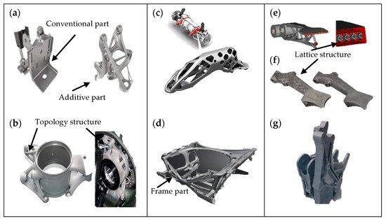
As with the lightweight design approaches for electrical machines, the automotive industry is increasingly using additively manufactured lightweight aluminium structural components, as shown in Figure 12, which are intended to help in further reducing vehicle weight. In most cases, this is achieved by optimising the topology to achieve the required stiffness properties while reducing weight.
Figure 12. (
a) Topology-optimised multifunctional anchor bracket [
10]; (
b) aluminium steering knuckle [
72]; (
c) topology-optimised aggregate carrier [
73]; (
d) functionally integrated vehicle front structure [
74]; (
e) topology-optimised brake pedal with lattice structure [
75]; (
f) lightweight brake pedal [
78]; (
g) additively manufactured topology-optimised adapter for EVs [
76,
77].
The topology-optimised seatbelt-buckle bracket was developed using metal 3D printing. In this way, eight components could be realised into one. The component was 40% lighter and 20% more resilient than that of the previous assembly (
Figure 12a) [
10].
Figure 12b shows a steering knuckle separately produced from AlSi10Mg and assembled. The challenge was to develop the lightest possible component with the greatest possible stiffness in order to keep the origin mass of the vehicle as low as possible. Too high a mass would result in poor spring-damping behaviour. The AM and the design enabled the mass of the component to be reduced by 35% (660 g), and the stiffness to be increased by 20% [
72].
The topology-optimised aggregate carrier illustrated in
Figure 12c was subject to a wide range of requirements, such as supporting the drive torques and transmitting the vehicle acceleration to the electrical machines. Furthermore, the components are an important element of the acoustic transmission path from the electrical machine and the transmission. In addition, they serve as a support in the event of a rear-end crash. Therefore, AM was used to produce a topology-optimised component that could meet the various requirements. The component was tested in extensive test series. In total, an acoustic improvement and a weight advantage of 1 kg per component (25% weight saving) could be achieved. A sand casting/hollow construction was referenced as a comparison [
73].
The front structure concept displayed in
Figure 12d shows the additively manufactured part from Scalmalloy. The design was applied according to real load cases in the automotive industry. In addition, it was designed to meet defined crash and vehicle safety requirements. The result was a lightweight front structure with integrated cooling channels and cooling fins, and the potential to integrate actuators and sensors directly into the component [
74].
The brake pedal was created utilising Iso-XFEM and lattice structures, and was manufactured with Ti–6Al–4V that had been selectively laser-melted. In order to lessen the severity of the high residual stresses that occur during the printing process, the thickness of the pad was increased, and the hollow area was filled with a body-centred cubic lattice structure because of its self-supporting cell structure. Overall, it lowered the volume, and increased the stability of the design shown in
Figure 12e [
75].
The lightweight Ti64 brake pedal produced by AM, as depicted in Figure 12f, weighed 22 g (11.6%) less while being more rigid compared to the weight of the previous model (190 g).
The development of a scalable and modular component as an adapter element for changeable integration into the overall axle drive system was the main goal in
Figure 12g. The SLM manufacturing process was then used to create the adapter element. A study that illustrates the design process with regard to integration on the vehicle side and implementation with regard to production was the end result [
76,
77].
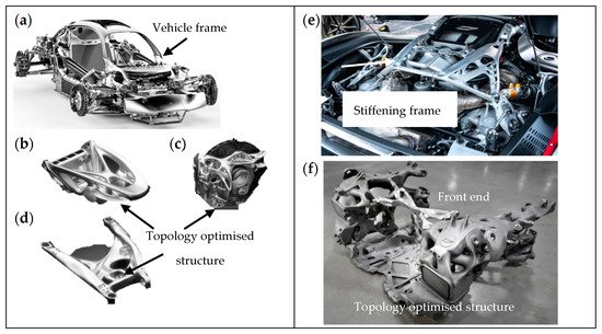
The Czinger 21C hypercar illustrates how AM can help in improving vehicle efficiency and performance. The vehicle comprises over 350 AM components, some of which are shown in
Figure 13a. All of these components were implemented throughout the vehicle from the frame to the control (
Figure 13b), braking (
Figure 13c), suspension (
Figure 13e), and exhaust systems. This resulted in component mass reductions averaging 15–20% or more in individual cases. In addition, the total mass of the vehicle consisted of 20% AM components. The two major applications that function as the main front and rear impact structures are presented in
Figure 13e,f [
79,
80]
Figure 13. (
a) Czinger 12C; (
b) steering column; (
c) brake-node brake component; (
d) rear lower control arm; (
e) engine bay; (
f) Rear structure assembly [
79,
80].
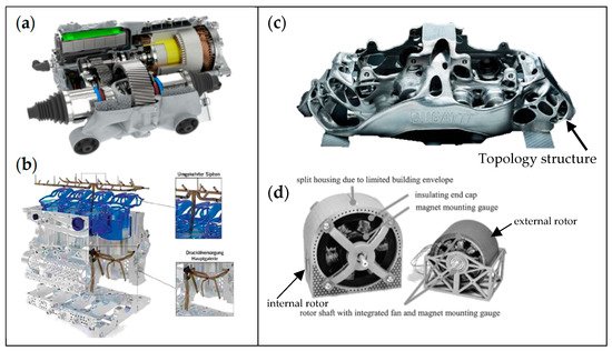
4.1. Mechanical Function Integrated Parts and Total Approaches
As shown in Figure 14, function-integrated and complete solutions produce components with as few individual components as possible, thus reducing assembly effort and implementing components more efficiently with the design freedom of AM. The result is a space-saving application with the same functionality.
Figure 14. (
a) AM-printed drivetrain unit [
39]; (
b) lubrication and cooling system of the internal combustion engine [
12]; (
c) Bugatti brake calliper [
8]; (
d) 3D-printed electrical drives [
81].
Figure 14a shows the 3D-printed prototype of a Porsche e-drive housing. With the prototype, several development stages could be implemented in one manufacturing process, and the assembly effort was reduced by around 40 work steps, and the weight of the housing components was reduced by 40% through the adaptation with regard to function integration and topology optimisation. So, it was also possible to integrate the transmission heat exchanger, which additionally improved the cooling of the entire drive. The entire e-drive experienced a weight reduction of around 10% due to the lattice structures. Due to the use of lattice structures, the housing had a continuous wall thickness of 1.5 mm, which increased the stiffness by 100%. A honeycomb structure designed on the outside of the drive ensured less vibration of the thin housing walls and significantly improved the acoustics [
39].
In the LeiMot Project, the weight of the cylinder head and crankcase was reduced by around 21% compared with a VW diesel engine. Furthermore, in addition to weight reduction, there was potential for efficiency gains. The latter could be achieved by reducing coolant and oil-pump capacity, reducing friction in the piston/liner assembly, reducing emissions during cold starts, and increasing the turbocharger turbine output by insulating the exhaust ports. A variety of AM approaches are used in the LeiMot concept. For example, internal cooling and oil ducts, lattice structures for mechanical use, and as flow elements, geometrically complex stiffening ribs, and integrated insulation systems (
Figure 14b) [
12].
The function-integrated design of the Bugatti brake calliper (
Figure 14c) was based on bionics and produced with titanium (Ti6Al4V). This enabled the topology-optimised component to save 40% (2 kg) of mass compared with its aluminium predecessor, while at the same time offering greater load-bearing capacity [
8].
Figure 14d illustrates the 3D-printed and optimised electrical drive. The number of used parts, and the weight of the housing and the bearing shield, were decreased in the feasibility analysis of the 3D printed electrical machine. Additionally, the integration of geometric features that would have not been conceivable utilising traditional manufacturing processes was possible. For better cooling, a fan wheel was incorporated inside the stator. Additionally, there was functional integration in the stator in the form of cooling channels [
81].
4.2. Mechanical Function Integrated Gearboxes and Gearings
Using the SLM method, the topology-optimised gear housing shown in
Figure 15a was created using AlSi10Mg. The majority of the article discusses topology optimisation, which was followed by a number of iterative processes before the final design was created. This was especially modified for additive manufacturing. In comparison to its cast equivalent, the resultant package geometry is 40% lighter, 10% more flexible by 98 percent safety. It combines lightweight design principles with improved oil management and load transfer efficiency. Additionally, the chosen 3D-printing method was unstable for components of this scale. Tests demonstrated that the gearbox satisfied the thermal specifications for standard gearboxes [
82].
Figure 15. (
a) Gearbox housing [
82]; (
b) topology optimised differential with internal structure [
83]; (
c) gear/shaft assembly with cooling ducts [
84]; (
d) pinion shaft with integrated cooling contours [
85].
For the topology-optimised differential of
Figure 15b, the AM process parameters for the case-hardened steel 20MnCr5 were determined by detailed static test design, microstructural analysis, and mechanical tests. In addition, great importance was attached to keeping the residual stresses of the additively manufactured components as low as possible in order to minimise the effort required for CNC postprocessing. The case hardening process was developed by considering the standard requirement for surface hardness and penetration depth. Through the use of tensile testing and hardness tests, it was feasible to obtain knowledge of mechanical properties, in this case, with respect to component pressure alignment, the heating of the metal powder during manufacture, stress-relief annealing after production, case hardening, and surface quality. A reference gear was used in order to provide comparison values. Using this high-performance material and the collected data, it was possible to manufacture the previously impossible design solution of a differential including a ring gear. This combination lead to a weight reduction of 13% (1 kg) and a higher stiffness of the gear [
83].
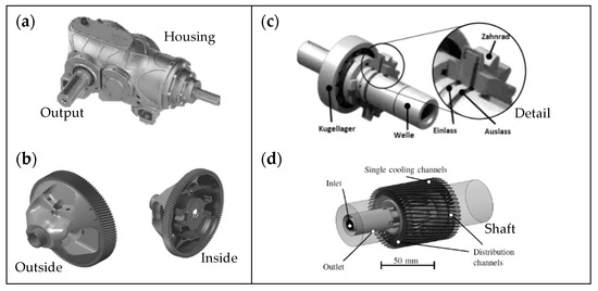
Figure 15c reports on the effect of functionally integrated near-contour cooling channels on 3D-printed gears in terms of efficiency and thermal management. In this case, the near-contour cooling helped in reducing the oil supply with regard to immersion lubrication and injection lubrication in the gear. Acceleration losses occur with injection lubrication, caused by the interaction of the injected oil and the squeezing losses because the oil is displaced during tooth contact. The gear was tested experimentally on an efficiency test rig under controlled injection lubrication. A glycose–water mixture was used as the cooling medium. The test results show that near-contour cooling reduced the temperature in the tooth geometry by up to 40 K and improved efficiency. As a result, the oil injection quantity could be significantly reduced, as less oil is required to cool the gear [
84]. For the pinion shaft in
Figure 15d, a strategy was adopted to cool the gear contour using near-contour liquid-carrying cooling channels in conjunction with ground tooth flanks and ta-C coating, providing optimal effectiveness in dry operation. The gear should then be produced using the 20MnCr5 alloy in the following phase. With a 5% deviation in dry operating efficiency, the goal was to minimise the weight of the gear stage, reduce noise emissions, and extend durability [
85].
5. Cost Analysis of Additive Components
The cost calculation of additive components is very diverse. There are different models for the cost calculation of the components. Some of the diverse costing models are software-based, architecture-based, task-based, and model-based. In these costing models, different criteria are used to calculate the costs, which does not allow for the uniform determination of the actual costs. The cost of restoration, the number of pieces, and the construction effort are often not taken into account [
86]. It is, therefore, useful to consider the costs along the product life cycle. In this way, the costs along the process chain of the product life cycle can be discussed individually and then summarised [
87]. However, it is often very important to obtain a rough cost estimate of components before the development or the process. For this purpose, widely used manufacturing service providers are a good way to determine the cost of an individual component. By querying several service providers for a component and then averaging the costs, the expected market price can be determined. However, it is not possible to establish a link between the costs and the expected component quality.
This entry is adapted from the peer-reviewed paper 10.3390/wevj13080154