Performance modelling is the abstraction of a real system into a simplified representation to enable the prediction of performance. The creation of a model can provide insight into how a proposed or actual system will or does work. This can, however, point towards different things to people belonging to different fields of work. Performance modelling has many benefits, which includes: A model will often be created specifically so that it can be interpreted by a software tool that simulates the system's behaviour, based on the information contained in the performance model. Such tools provide further insight into the system's behaviour and can be used to identify bottlenecks or hot spots where the design is inadequate. Solutions to the problems identified might involve the provision of more physical resources or change in the structure of the design. Performance modelling is found helpful, in case of: Modelling of a transmission line is done to analyse its performance and characteristics. The gathered information vis simulating the model can be used to reduce losses or to compensate these losses. Moreover, it gives more insight into the working of transmission lines and helps to find a way to improve the overall transmission efficiency with minimum cost.
- model
- physical resources
- modelling
1. Overview
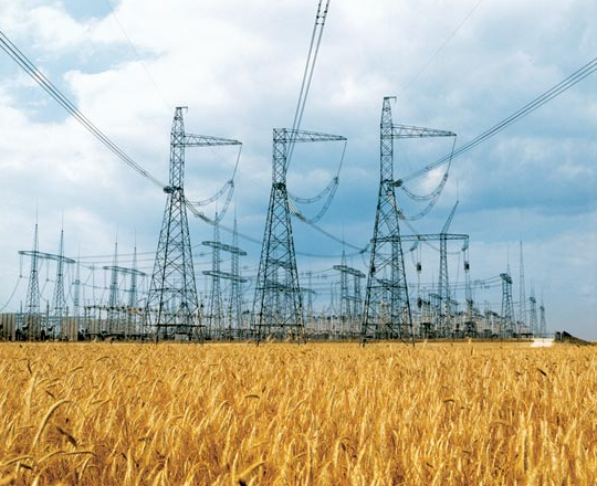
Electric power transmission is the bulk movement of electrical energy from a generating site, such as a power plant, to an electrical substation and is different from the local wiring between high-voltage substations and customers, which is typically referred to as electric power distribution. The interconnected network which facilitates this movement is known as a transmission line. A transmission line is a set of electrical conductors carrying an electrical signal from one place to another. Coaxial cable and twisted pair cable are examples. The transmission line is capable of transmitting electrical power from one place to another. In many electric circuits, the length of the wires connecting the components can, for the most part, be ignored. That is, the voltage on the wire at a given time can be assumed to be the same at all points. However, when the voltage changes in a time interval comparable to the time it takes for the signal to travel down the wire, the length becomes important and the wire must be treated as a transmission line. Stated another way, the length of the wire is important when the signal includes frequency components with corresponding wavelengths comparable to or less than the length of the wire. So far transmission lines are categorized and defined in many ways. Few approaches to modelling have also being done by different methods. Most of them are mathematical and assumed circuit-based models.
Transmission can be of two types :
- HVDC Transmission (High Voltage Direct Current transmission)
- HVAC Transmission (High Voltage Alternating Current Transmission)
1.1. HVDC Transmission
High-voltage direct current (HVDC) is used to transmit large amounts of power over long distances or for interconnections between asynchronous grids. When electrical energy is to be transmitted over very long distances, the power lost in AC transmission becomes appreciable and it is less expensive to use direct current instead of alternating current.[1] For a very long transmission line, these lower losses (and reduced construction cost of a DC line) can offset the additional cost of the required converter stations at each end.In DC transmission line, the mercury arc rectifier converts the alternating current into the DC.[2] The DC transmission line transmits the bulk power over long distance. At the consumer ends the thyratron converts the DC into the AC.[3]
1.2. HVAC Transmission
The AC transmission line is used for transmitting the bulk of the power generation end to the consumer end.[4] The power is generated in the generating station. The transmission line transmits the power from generation to the consumer end. High-voltage power transmission allows for lesser resistive losses over long distances in the wiring.[4] This efficiency of high voltage transmission allows for the transmission of a larger proportion of the generated power to the substations and in turn to the loads, translating to operational cost savings. The power is transmitted from one end to another with the help of step-up and step down transformer. Most transmission lines are high-voltage three-phase alternating current (AC), although single phase AC is sometimes used in railway electrification systems. Electricity is transmitted at high voltages (115 kV or above) to reduce the energy loss which occurs in long-distance transmission.
Power is usually transmitted through overhead power lines.[5] Underground power transmission has a significantly higher installation cost and greater operational limitations,[5] but reduced maintenance costs.[6] Underground transmission is sometimes used in urban areas or environmentally sensitive locations.[6]
2. Terminologies
2.1. Lossless Line

The lossless line approximation is the least accurate model; it is often used on short lines when the inductance of the line is much greater than its resistance. For this approximation, the voltage and current are identical at the sending and receiving ends.
The characteristic impedance is purely real, which means resistive for that impedance, and it is often called surge impedance for a lossless line. When a lossless line is terminated by surge impedance, there is no voltage drop. Though the phase angles of voltage and current are rotated, the magnitudes of voltage and current remain constant along the length of the line. For load > SIL, the voltage will drop from sending end and the line will “consume” VARs. For load < SIL, the voltage will increase from sending end, and the line will generate VARs.
2.2. Power Factor
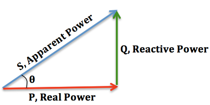
In electrical engineering, the power factor of an AC electrical power system is defined as the ratio of the real power absorbed by the load to the apparent power flowing in the circuit, and is a dimensionless number in the closed interval of −1 to 1. A power factor of less than one indicates the voltage and current are not in phase, reducing the instantaneous product of the two. A negative power factor occurs when the device (which is normally the load) generates power, which then flows back towards the source.
- Real power is the instantaneous product of voltage and current and represents the capacity of the electricity for performing work.
- Apparent power is the average product of current and voltage. Due to energy stored in the load and returned to the source, or due to a non-linear load that distorts the wave shape of the current drawn from the source, the apparent power may be greater than the real power(pf ≤0.5).
In an electric power system, a load with a low power factor draws more current than a load with a high power factor for the same amount of useful power transferred. The higher currents increase energy loss in the distribution system and require larger wires and other equipment. Because of the costs of larger equipment and wasted energy, electrical utilities will usually charge a higher cost to industrial or commercial customers where there is a low power factor.
2.3. Surge Impedance
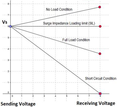
The characteristic impedance or surge impedance (usually written Z0) of a uniform transmission line is the ratio of the amplitudes of voltage and current of a single wave propagating along the line; that is, a wave travelling in one direction in the absence of reflections in the other direction. Alternatively and equivalently it can be defined as the input impedance of a transmission line when its length is infinite. Characteristic impedance is determined by the geometry and materials of the transmission line and, for a uniform line, is not dependent on its length. The SI unit of characteristic impedance is Ohm (Ώ)
Surge impedance determines the loading capability of the line and reflection coefficient of the current or voltage propagating waves. [math]\displaystyle{ Z_{0}=\sqrt{\frac{L}{C}} }[/math]
Where,
Z0 = Characteristic Impedance of the Line L = Inductance per unit length of the Line C = Capacitance per unit length of the Line
2.4. Line Parameters
The transmission line has mainly four parameters, resistance, inductance, and capacitance and shunt conductance.[7] These parameters are uniformly distributed along the line. Hence, it is also called the distributed parameter of the transmission line.
2.5. Ferranti Effect
File:Ferranti Cable Vector.svg In electrical engineering, the Ferranti effect is the increase in voltage occurring at the receiving end of a very long (> 200 km) AC electric power transmission line, relative to the voltage at the sending end, when the load is very small, or no load is connected. It can be stated as a factor, or as a percent increase:.[8]
The capacitive line charging current produces a voltage drop across the line inductance that is in-phase with the sending-end voltage, assuming negligible line resistance. Therefore, both line inductance and capacitance are responsible for this phenomenon. This can be analysed by considering the line as a transmission line where the source impedance is lower than the load impedance (unterminated). The effect is similar to an electrically short version of the quarter-wave impedance transformer, but with smaller voltage transformation.
The Ferranti effect is more pronounced the longer the line and the higher the voltage applied.[9] The relative voltage rise is proportional to the square of the line length and the square of frequency.[10]
The Ferranti effect is much more pronounced in underground cables, even in short lengths, because of their high capacitance per unit length, and lower electrical impedance.
2.6. Corona Discharge
A corona discharge is an electrical discharge brought on by the ionization of a fluid such as air surrounding a conductor that is electrically charged. Spontaneous corona discharges occur naturally in high-voltage systems unless care is taken to limit the electric field strength. A corona will occur when the strength of the electric field (potential gradient) around a conductor is high enough to form a conductive region, but not high enough to cause electrical breakdown or arcing to nearby objects. It is often seen as a bluish (or another colour) glow in the air adjacent to pointed metal conductors carrying high voltages and emits light by the same property as a gas discharge lamp.
In many high voltage applications, the corona is an unwanted side effect. Corona discharge from high voltage electric power transmission lines constitutes an economically significant waste of energy. Corona discharges are suppressed by improved insulation, corona rings, and making high voltage electrodes in smooth rounded shapes.
2.7. ABCD Parameters
A, B, C, D are the constants also known as the transmission parameters or chain parameters. These parameters are used for the analysis of an electrical network. It is also used for determining the performance of input, output voltage and current of the transmission network.
2.8. Propagation Constant
The propagation constant of the sinusoidal electromagnetic wave is a measure of the change undergone by the amplitude and phase of the wave as it propagates in a given direction. The quantity being measured can be the voltage, the current in a circuit, or a field vector such as electric field strength or flux density. The propagation constant itself measures the change per unit length, but it is otherwise dimensionless. In the context of two-port networks and their cascades, propagation constant measures the change undergone by the source quantity as it propagates from one port to the next.
Attenuation constant
The real part of the propagation constant is the attenuation constant and is denoted by Greek lowercase letter α (alpha). It causes signal amplitude to decrease along a transmission line.
Phase constant
The imaginary part of the propagation constant is the phase constant and is denoted by Greek lowercase letter β (beta). It causes the signal phase to shift along a transmission line. Generally denoted in radians per meter (rad/m).
The propagation constant is denoted by Greek lowercase letter γ (gamma), and γ = α + jβ
2.9. Voltage Regulation
Voltage regulation is a measure of the change in the voltage magnitude between the sending and receiving end of a component, such as a transmission or distribution line. It is given in percentage for different lines.
Mathematically, voltage regulation is given by,
[math]\displaystyle{ V.R = \frac{V_{no-load}-V_{full-load}}{V_{no-load}} }[/math]
3. Line Parameters of AC Transmission
The AC transmission has four line parameters, these are the series resistance & inductance, and shunt capacitance and admittance. These parameters are responsible for distinct behavior of voltage and current waveforms along the transmission line. Line parameters are generally represented in their respective units per Km of length in transmission lines. So these parameters depend upon the geometric alignment of transmission lines (no of conductors used, shape of conductors, physical spacing between conductors and height above the ground etc). These parameters are independent of current and voltage of any of the sending or receiving ends.
3.1. Series Resistance
Definition
The electrical resistance of an object is property of a substance due to which it restricts the flow of electric current due to a potential difference in its two ends.[11] The inverse quantity is electrical conductance, and is the ease with which an electric current passes. Electrical resistance shares some conceptual parallels with the notion of mechanical friction. The SI unit of electrical resistance is the ohm (Ω), while electrical conductance is measured in siemens (S).
Characteristics
The resistance of an object depends in large part on the material it is made of—objects made of electrical insulators like rubber tend to have very high resistance and low conductivity, while objects made of electrical conductors like metals tend to have very low resistance and high conductivity. This material dependence is quantified by resistivity or conductivity. However, resistance and conductance are extensive rather than bulk properties, meaning that they also depend on the size and shape of an object. For example, a wire's resistance is higher if it is long and thin, and lower if it is short and thick. All objects show some resistance, except for superconductors, which have a resistance of zero.
The resistance (R) of an object is defined as the ratio of voltage across it (V) to current through it (I), while the conductance (G) is the inverse:
- [math]\displaystyle{ R = {V\over I}, \qquad G = {I\over V} = \frac{1}{R} }[/math]
For a wide variety of materials and conditions, V and I are directly proportional to each other, and therefore R and G are constants (although they will depend on the size and shape of the object, the material it is made of, and other factors like temperature or strain). This proportionality is called Ohm's law, and materials that satisfy it are called ohmic materials. In other cases, such as a transformer, diode or battery, V and I are not directly proportional. The ratio V/I is sometimes still useful, and is referred to as a "chordal resistance" or "static resistance",[12][13] since it corresponds to the inverse slope of a chord between the origin and an I–V curve. In other situations, the derivative [math]\displaystyle{ \frac{dV}{dI} \,\! }[/math] may be most useful; this is called the "differential resistance".
Transmission lines, as they consist of conducting wires of very long length, have an electrical resistance that can't be neglected at all.
3.2. Series Inductance
Definition
When current flows within a conductor, magnetic flux is set up. With the variation of current in the conductor, the number of lines of flux also changes, and an emf is induced in it (Faraday's Law). This induced emf is represented by the parameter known as inductance. It is customary to use the symbol L for inductance, in honour of the physicist Heinrich Lenz.
In the SI system, the unit of inductance is the henry (H), which is the amount of inductance which causes a voltage of 1 volt when the current is changing at a rate of one ampere per second. It is named for Joseph Henry, who discovered inductance independently of Faraday.[14]
Types of inductance
The flux linking with the conductor consists of two parts, namely, the internal flux and the external flux :
- The internal flux is induced due to the current flow in the conductor.
- The external flux produced around the conductor is due to its current and the current of the other conductors place around it. The total inductance of the conductor is determined by the calculation of the internal and external flux.
Characteristics
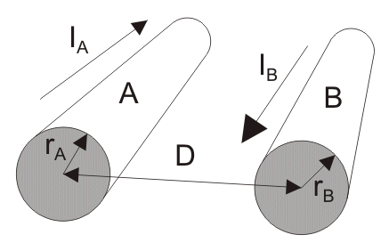
The transmission line wiring is also inductive in nature and, the inductance of a single circuit line can be given mathematically by : [math]\displaystyle{ L= \frac{\mu_0}{2 \pi} ln\frac{D}{r\prime} H/m }[/math]
Where,
- D is the physical spacing between the conductors.
- [math]\displaystyle{ r\prime = re^{-1/4} }[/math] is the radius of the fictitious conductor having no internal flux linkages but with the same inductace as the original conductor of radius r. A quantity of [math]\displaystyle{ e^{-1/4} }[/math](=0.7788 appx.) is multiplied with the actual radius of conductor in order to account for the internal flux linkages(applicable to solid round conductors only).[15]
- [math]\displaystyle{ \mu_0 }[/math] is the permeability of free space and [math]\displaystyle{ {\mu_0} = 4 \pi \times 10^{-7} H/m }[/math].
For transposed lines with two or more phases, the inductance between any two lines can be calculated using : [math]\displaystyle{ L= \frac{\mu_0}{2 \pi} ln\frac{D_{GMD}}{r\prime} H/m }[/math].
Where, [math]\displaystyle{ D_{GMD} }[/math] is the geometric mean distance in between the conductors.
If the lines are not properly transposed, the inductances become unequal and contain imaginary terms due to mutual inductances. In case of proper transposition, all the conductors occupy the available positions equal distance and thus the imaginary terms are cancelled out. And all the line inductances become equal.
3.3. Shunt Capacitance
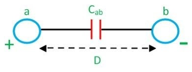
Line capacitance
Definition
Capacitance is the ratio of the change in an electric charge in a system to the corresponding change in its electric potential. The capacitance is a function only of the geometry of the design (e.g. area of the plates and the distance between them) and the permittivity of the dielectric material between the plates of the capacitor. For many dielectric materials, the permittivity and thus the capacitance is independent of the potential difference between the conductors and the total charge on them.
The SI unit of capacitance is the farad (symbol: F), named after the English physicist Michael Faraday. A 1 farad capacitor, when charged with 1 coulomb of electrical charge, has a potential difference of 1 volt between its plates.[16] The reciprocal of capacitance is called elastance.
Types of capacitance
There are two closely related notions of capacitance self-capacitance and mutual capacitance :
- For an isolated conductor, there exists a property called self-capacitance, which is the amount of electric charge that must be added to an isolated conductor to raise its electric potential by one unit (i.e. one volt, in most measurement systems).[17] The reference point for this potential is a theoretical hollow conducting sphere, of infinite radius, with the conductor centered inside this sphere. Any object that can be electrically charged exhibits self-capacitance. A material with a large self-capacitance holds a more electric charge at a given voltage than one with low self-capacitance.
- The notion of mutual capacitance is particularly important for understanding the operations of the capacitor, one of the three elementary linear electronic components (along with resistors and inductors).In electrical circuits, the term capacitance is usually a shorthand for the mutual capacitance between two adjacent conductors, such as the two plates of a capacitor.
Charecteristics
Transmission line conductors constitute a capacitor between them, exhibiting mutual capacitance. The conductors of the transmission line act as a parallel plate of the capacitor and the air is just like a dielectric medium between them. The capacitance of a line gives rise to the leading current between the conductors. It depends on the length of the conductor. The capacitance of the line is proportional to the length of the transmission line. Their effect is negligible on the performance of lines with a short length and low voltage. In the case of high voltage and long lines, it is consideredTemplate:By whomst as one of the most important parameters. The shunt capacitance of the line is responsible for Ferranti effect.[18]
The capacitance of a single phase transmission line can be given mathematically by : [math]\displaystyle{ C_{ab} = \frac{\pi \epsilon_0}{ln\frac{D}{r}} F/m }[/math]
Where,
- D is the physical spacing between the conductors.
- r is the radius of each conductor.
- [math]\displaystyle{ \epsilon_0 }[/math] is the permittivity of air and [math]\displaystyle{ {\epsilon_0} = 8.854 \times 10^{-12} }[/math]
For lines with two or more phases, the capacitance between any two lines can be calculated using : [math]\displaystyle{ C = \frac{\pi \epsilon_0}{ln\frac{D_{GMD}}{r}} F/m }[/math]
Where, [math]\displaystyle{ D_{GMD} }[/math] is the geometric mean distance of the conductors.
The effect of self-capacitance, on a transmission line, is generally neglected because the conductors are not isolated and thus there exists no detectable self-capacitance.
3.4. Shunt Admittance
Definition
In electrical engineering, admittance is a measure of how easily a circuit or device will allow a current to flow. It is defined as the reciprocal of impedance. The SI unit of admittance is the siemens (symbol S); the older, synonymous unit is mho, and its symbol is ℧ (an upside-down uppercase omega Ω). Oliver Heaviside coined the term admittance in December 1887.[19]
Admittance is defined as
- [math]\displaystyle{ Y \equiv \frac{1}{Z} \, }[/math]
where
- Y is the admittance, measured in siemens
- Z is the impedance, measured in ohms
Characteristics
Resistance is a measure of the opposition of a circuit to the flow of a steady current, while impedance takes into account not only the resistance but also dynamic effects (known as reactance). Likewise, admittance is not only a measure of the ease with which a steady current can flow but also the dynamic effects of the material's susceptance to polarization:
- [math]\displaystyle{ Y = G + j B \, }[/math]
where
- [math]\displaystyle{ Y }[/math] is the admittance, measured in siemens.
- [math]\displaystyle{ G }[/math] is the conductance, measured in siemens.
- [math]\displaystyle{ B }[/math] is the susceptance, measured in siemens.
- [math]\displaystyle{ j^2 = -1 }[/math]
The dynamic effects of the material's susceptance relate to the universal dielectric response, the power-law scaling of a system's admittance with frequency under alternating current conditions.
In the context of electrical modelling of transmission lines, shunt components that provide paths of least resistance in certain models are generally specified in terms of their admittance. Transmission lines can span hundreds of kilometres, over which the line's capacitance can affect voltage levels. For short length transmission line analysis, this capacitance can be ignored and shunt components are not necessary for the model. Lines with more length, contain a shunt admittance governed by[20]
[math]\displaystyle{ Y=yl=j\omega Cl }[/math]
where
Y – total shunt admittance
y – shunt admittance per unit length
l – length of the line
C – capacitance of the line
4. Modelling of Transmission Lines
4.1. Two Port Networks
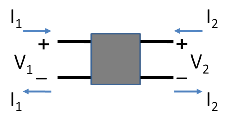
A two-port network (a kind of four-terminal network or quadripole) is an electrical network (circuit) or device with two pairs of terminals to connect to external circuits. Two terminals constitute a port if the currents applied to them satisfy the essential requirement known as the port condition: the electric current entering one terminal must equal the current emerging from the other terminal on the same port.[21][22] The ports constitute interfaces where the network connects to other networks, the points where signals are applied or outputs are taken. In a two-port network, often port 1 is considered the input port and port 2 is considered the output port.
The two-port network model is used in mathematical circuit analysis techniques to isolate portions of larger circuits. A two-port network is regarded as a "black box" with its properties specified by a matrix of numbers. This allows the response of the network to signals applied to the ports to be calculated easily, without solving for all the internal voltages and currents in the network. It also allows similar circuits or devices to be compared easily. For example, transistors are often regarded as two-ports, characterized by their h-parameters (see below) which are listed by the manufacturer. Any linear circuit with four terminals can be regarded as a two-port network provided that it does not contain an independent source and satisfies the port conditions.
4.2. Transmission Matrix and ABCD Parameters

Oftentimes, we are only interested in the terminal characteristics of the transmission line, which are the voltage and current at the sending and receiving ends, for performance analysis of the line. The transmission line itself is then modelled as a "black box" and a 2 by 2 transmission matrix is used to model its behaviour, as follows[23][24]
- [math]\displaystyle{ \begin{bmatrix} V_\mathrm{S}\\ I_\mathrm{S}\\ \end{bmatrix} = \begin{bmatrix} A & B\\ C & D\\ \end{bmatrix} \begin{bmatrix} V_\mathrm{R}\\ I_\mathrm{R}\\ \end{bmatrix} }[/math]
Derivation
This equation in matrix form, consists of two individual equations as stated below:[25]
[math]\displaystyle{ V_S = AV_R + BI_R }[/math]
[math]\displaystyle{ I_S = CV_R + DI_R }[/math]
Where,
[math]\displaystyle{ V_S }[/math] is the sending end voltage
[math]\displaystyle{ V_R }[/math] is the receiving end voltage
[math]\displaystyle{ I_S }[/math] is the sending end current
[math]\displaystyle{ I_R }[/math] is the receiving end current
- Now, if we apply open circuit at the receiving end, the effective load current will be zero (i.e. IR = 0)
1.[math]\displaystyle{ A = \frac{V_S}{V_R} }[/math]
So, the parameter A is the ratio of sending end voltage to receiving end voltage, thus called the voltage ratio. Being the ratio of two same quantities, the parameter A is unitless.
2.[math]\displaystyle{ C= \frac{I_S}{V_R} }[/math]
So, the parameter C is the ratio of sending end current to receiving end voltage, thus called the transfer admittance and the unit of C is Mho ([math]\displaystyle{ \mho }[/math]).
- Now, if we apply short circuit at the receiving end, the effective receiving end voltage will be zero (i.e. VR = 0)
1.[math]\displaystyle{ B = \frac{V_S}{I_R} }[/math]
So, the parameter B is the ratio of sending end voltage to receiving end current, thus called the transfer impedance and the unit of C is Ohm (Ω).
2.[math]\displaystyle{ D = \frac{I_S}{I_R} }[/math]
So, the parameter D is the ratio of sending end current to receiving end current, thus called the current ratio. Being the ratio of two same quantities, the parameter D is unitless.
ABCD parameter values
To summarize, ABCD Parameters for a two port(four terminal) passive, linear and bilateral network is given as :
| Parameters | Parameter Name | Value | Unit |
|---|---|---|---|
| A | Voltage ratio | [math]\displaystyle{ \left . \frac{V_S}{V_R} \right |_{I_R = 0} }[/math] | Unit less |
| B | Transfer impedance | [math]\displaystyle{ \left . \frac{V_S}{I_R} \right |_{V_R = 0} }[/math] | Ohm (Ώ) |
| C | Transfer admittance | [math]\displaystyle{ \left . \frac{I_S}{V_R} \right |_{I_R = 0} }[/math] | Mho ([math]\displaystyle{ \mho }[/math]) |
| D | Current ratio | [math]\displaystyle{ \left . \frac{I_S}{I_R} \right |_{V_R = 0} }[/math] | Unit less |
Properties
The line is assumed to be a reciprocal, symmetrical network, meaning that the receiving and sending labels can be switched with no consequence. The transmission matrix T also has the following properties:
- The A, B, C and D constants are complex numbers due to the complex values of transmission parameters. And because of the complex nature, they are represented as Vectors in the Complex Plane (phasors).
- [math]\displaystyle{ \det(T) = AD - BC = 1 }[/math] (Condition for reciprocity)
- [math]\displaystyle{ A = D }[/math] (condition for symmetry)
The parameters A, B, C, and D differ depending on how the desired model handles the line's resistance (R), inductance (L), capacitance (C), and shunt (parallel, leak) conductance G. The four main models are the short line approximation, the medium line approximation, the long line approximation (with distributed parameters), and the lossless line. In all models described, a capital letter such as R refers to the total quantity summed over the line and a lowercase letter such as r refers to the per-unit-length quantity.
5. Classification of AC Transmission Line
5.1. Classification Overview
The AC transmission line has resistance R, inductance L, capacitance C and the shunt or leakage conductance G. These parameters along with the load and the transmission line determines the performance of the line. The term performance means the sending end voltage, sending end currents, sending end factor, power loss in the line, efficiency of the transmission line, regulate and limit of power flow during efficiency and transmission, regulation and limits of power during the steady-state and transient condition. AC transmission line is generally categorized into three classes[27]
- Short Transmission Line (line length ≤ 60 Km)
- Medium Transmission Line (80 Km ≤ Line length ≤ 250 Km)
- Long Transmission Line (Line length ≥ 250 Km)
The classification of the transmission line depends on the frequency of power transfer and is an assumption made for ease of calculation of line performance parameters and its losses.[28] And because this, the range of length for the categorization of a transmission line is not rigid. The ranges of length may vary (a little), and all of them are valid in their areas of approximation.
5.2. Basis of Classification
Derivation of voltage\current wavelength
Current and voltage propagate in a transmission line with a speed equal to the speed of light (c) i.e. appx. [math]\displaystyle{ 3 \times 10^8 m/sec = 3 \times 10^5 km/sec }[/math] and the frequency (f) of voltage or current is 50 Hz ( although in the America and parts of Asia it is typically 60 Hz)[29]
Therefore, wavelength (λ) can be calculated as below :
[math]\displaystyle{ f \lambda = c }[/math]
or, [math]\displaystyle{ \lambda = \frac{c}{f} }[/math]
or, [math]\displaystyle{ \lambda = \frac{3 \times 10^5}{50} = 6000 Km }[/math]
Reason behind classification
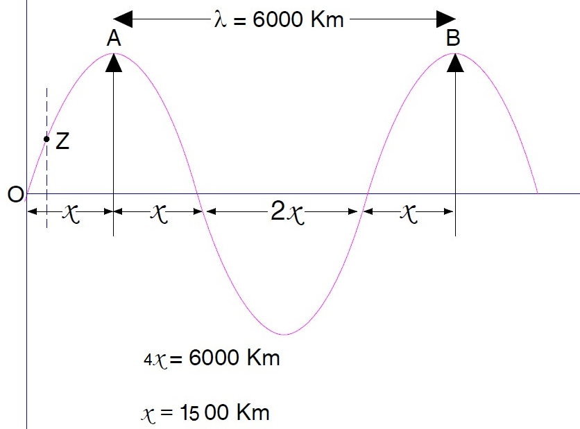
Now, A transmission line with 60 km of length is very very small([math]\displaystyle{ \tfrac{1}{100} }[/math] times) when compared with wavelength i.e. 6000 km. Up to 240 km ([math]\displaystyle{ \tfrac{1}{25} }[/math] times of wavelength) (250 km is taken for easy remembering) length of the line, current or voltage waveform is so small that it can be approximated to a straight line for all practical purposes. For line length of about 240 km parameters are assumed to be lumped (though practically these parameters are always distributed). Therefore the response of transmission line for a length up to 250 km can be considered linear and hence the equivalent circuit of the line can be approximated to a linear circuit. But if the length of the line is more than 250 km say 400 km i.e. [math]\displaystyle{ \tfrac{1}{15} }[/math] times of wavelength, then the waveform of current or voltage can not be considered linear and therefore we need to use integration for the analysis of these lines.
- For the lines of up to 60 km of length is so short, that the effect of shunt parameters are nearly undetectable throughout the line. And hence, these linear lines are categorized as Short Transmission Lines.
- For the lines of effective length in between 60 km to 250 km, the effect of shunt parameters can not be neglected. And hence, they are assumed as lumped either at the middle of the line (a nominal T representation) or at the two ends of the line (a nominal Π representation). These linear lines are categorized as Medium Transmission Lines
- For transmission lines of effective length above 250 km, the equivalent circuit can not be considered as linear. The parameters are distributed and rigorous calculations are required for performance analysis. These non-linear lines are categorized as Long Transmission Lines.
6. Short Transmission Line
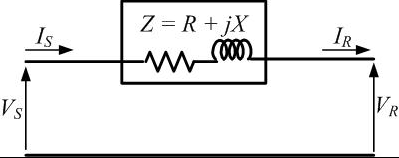
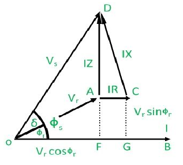
The transmission lines which have a length less than 60 km are generally referred to as short transmission lines. For its short length, parameters like electrical resistance, impedance and inductance of these short lines are assumed to be lumped. The shunt capacitance for a short line is almost negligible and thus, are not taken into account (or assumed to be zero).
6.1. Derivation of ABCD Parameter Values
Now, if the impedance per km for an l km of line is, [math]\displaystyle{ z_{0} = r + j x }[/math] and the sending end & receiving end voltages make an angle of [math]\displaystyle{ \Phi_s }[/math] & [math]\displaystyle{ \Phi_r }[/math] respectively, with the receiving end current. Then, the total impedance of the line will be, [math]\displaystyle{ Z = lr + ljx }[/math]
The sending end voltage and current for this approximation are given by :
-
[math]\displaystyle{ V_{S} = V_R + ZI_R }[/math]
()
-
[math]\displaystyle{ I_S = I_R }[/math]
()
In this, the sending and receiving end voltages are denoted by [math]\displaystyle{ V_S }[/math] and [math]\displaystyle{ V_R }[/math] respectively. Also the currents [math]\displaystyle{ I_S }[/math] and [math]\displaystyle{ I_R }[/math] are entering and leaving the network respectively.
So, by considering the equivalent circuit model for the short transmission line, the transmission matrix can be obtained as follows:
-
[math]\displaystyle{ \begin{bmatrix} V_\mathrm{S}\\ I_\mathrm{S}\\ \end{bmatrix} = \begin{bmatrix} 1 & Z \\ 0 & 1\\ \end{bmatrix} \begin{bmatrix} V_\mathrm{R}\\ I_\mathrm{R}\\ \end{bmatrix} }[/math]
()
Therefore, the ABCD parameters are given by :
A = D =1, B = Z Ω and C = 0
7. Medium Transmission Line
The transmission line having its effective length more than 80 km but less than 250 km is generally referred to as a medium transmission line. Due to the line length being considerably high, shunt capacitance along with admittance Y of the network does play a role in calculating the effective circuit parameters, unlike in the case of short transmission lines. For this reason, the modelling of a medium length transmission line is done using lumped shunt admittance along with the lumped impedance in series to the circuit.
Counterintuitive behaviours of medium-length transmission lines:
- voltage rise at no load or small current (Ferranti effect)
- receiving-end current can exceed sending-end current
These lumped parameters of a medium length transmission line can be represented using two different models, namely :
7.1. Nominal Π Representation
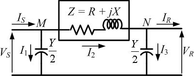
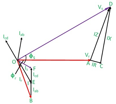
In case of a nominal Π representation, the total lumped shunt admittance is divided into 2 equal halves, and each half with value Y ⁄ 2 is placed at both the sending & receiving end, while the entire circuit impedance is lumped in between the two halves. The circuit, so formed resembles the symbol of pi (Π), hence is known as the nominal Π (or Π network representation) of a medium transmission line. It is mainly used for determining the general circuit parameters and performing load flow analysis.
Derivation of ABCD parameter values
Applying KCL at the two shunt ends, we get
[math]\displaystyle{ I_S = I_1 + I_2 = \frac{Y}{2}V_S + \frac{Y}{2}V_R + I_R }[/math]
In this,
The sending and receiving end voltages are denoted by [math]\displaystyle{ V_S }[/math] and [math]\displaystyle{ V_R }[/math] respectively. Also the currents [math]\displaystyle{ I_S }[/math] and [math]\displaystyle{ I_R }[/math] are entering and leaving the network respectively.
[math]\displaystyle{ I_1 \& I_3 }[/math] are the currents through the shunt capacitances at the sending and receiving end respectively whereas [math]\displaystyle{ I_2 }[/math] is the current through the series impedance.
Again,
[math]\displaystyle{ V_S = ZI_2 + V_R = Z(V_R \frac{Y}{2} + I_R) + V_R }[/math]
or,
-
[math]\displaystyle{ V_S = (1 + \frac{YZ}{2})V_R + ZI_R }[/math]
()
So, by substituting we get :
[math]\displaystyle{ I_S = \frac{Y}{2}[(1 + \frac{YZ}{2})V_R + ZI_R] + \frac{Y}{2}V_R + I_R }[/math]
or,
-
[math]\displaystyle{ I_S = Y(1 + \frac{YZ}{4})V_R + (1 + \frac{YZ}{2})I_R }[/math]
()
The equation obtained thus, eq(4) & (5) can be written into matrix form as follows :
-
[math]\displaystyle{ \begin{bmatrix} V_{S}\\ I_{S}\\ \end{bmatrix} = \begin{bmatrix} 1 + \frac{YZ}{2} & Z \\ Y(1+ \frac{YZ}{4}) & 1 + \frac{YZ}{2} \end{bmatrix} \begin{bmatrix} V_{R}\\ I_{R}\\ \end{bmatrix} }[/math]
()
so, the ABCD parameters are :
A = D =[math]\displaystyle{ (1 + \frac{YZ}{2}) }[/math] per unit
B =Z Ω
C = [math]\displaystyle{ Y(1 + \frac{YZ}{4}) \mho }[/math]
7.2. Nominal T Representation

Medium Transmission Line (T representation)
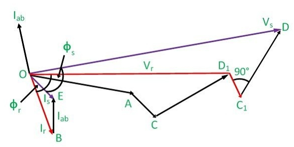
In the nominal T model of a medium transmission line, the net series impedance is divided into two halves and placed on either side of the lumped shunt admittance i.e. placed in the middle. The circuit so formed resembles the symbol of a capital T or star(Y), and hence is known as the nominal T network of a medium length transmission line.
derivation of ABCD patameter values
The application of KCL at the juncture(the neutral point for Y connection) gives,
[math]\displaystyle{ V_J = \frac{V_S - V_J}{\frac{Z}{2}} = YV_J + \frac{V_J - V_R}{\frac{Z}{2}} }[/math]
The above equation can be rearranged as,
[math]\displaystyle{ V_J = \frac{2}{YZ+4}(V_S + V_R) }[/math]
Here, the sending and receiving end voltages are denoted by [math]\displaystyle{ V_S }[/math] and [math]\displaystyle{ V_R }[/math] respectively. Also the currents [math]\displaystyle{ I_S }[/math] and [math]\displaystyle{ I_R }[/math] are entering and leaving the network respectively
Now, for the receiving end current, we can write :
-
[math]\displaystyle{ I_R = \frac{V_J - V_R}{\frac{Z}{2}} }[/math]
()
By rearranging the equation and replacing the value of [math]\displaystyle{ V_J }[/math] with the derived value, we get :
-
[math]\displaystyle{ V_S = (1 + \frac{YZ}{2})V_R + Z(1 + \frac{YZ}{4})I_R }[/math]
()
Now, the sending end current can be written as:
[math]\displaystyle{ I_S = YV_J + I_R }[/math]
Replacing the value of [math]\displaystyle{ V_J }[/math] in the above equation :
-
[math]\displaystyle{ I_S = YV_R + (1 + \frac{YZ}{2})I_R }[/math]
()
The equation obtained thus, eq.(8) & eq.(9) can be written into matrix form as follows :
-
[math]\displaystyle{ \begin{bmatrix} V_{S}\\ I_{S}\\ \end{bmatrix} = \begin{bmatrix} 1 + \frac{YZ}{2} & Z(1+ \frac{YZ}{4}) \\ Y & 1 + \frac{YZ}{2} \end{bmatrix} \begin{bmatrix} V_{R}\\ I_{R}\\ \end{bmatrix} }[/math]
()
So, the ABCD parameters are :
A = D =[math]\displaystyle{ (1 + \frac{YZ}{2}) }[/math] per unit
B = [math]\displaystyle{ Z(1+ \frac{YZ}{4}) \Omega }[/math]
C =[math]\displaystyle{ Y \mho }[/math]
8. Long Transmission Line
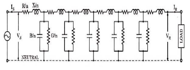
A transmission line having a length more than 250 km is considered as a long transmission line. Unlike short and medium lines the line parameters of long transmission line are assumed to be distributed at each point of line uniformly. Thus modelling of a long line is somewhat difficult. But few approaches can be made based on the length and values of line parameters. For a long transmission line, it is considered that the line may be divided into various sections, and each section consists of inductance, capacitance, resistance and conductance, as shown in the RLC (resistance and inductance in series, with shunt capacitance) cascade model.
8.1. Derivation of ABCD Parameter Values
Cascaded Model approach

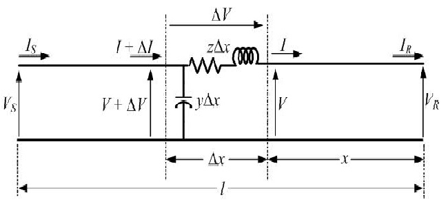
Considering a bit smaller part of a long transmission line having length dx situated at a distance x from the receiving end. The series impedance of the line is represented by zdx and ydx is the shunt impedance of the line. Due to charging current and corona loss, the current is not uniform along the line. Voltage is also different in different parts of the line because of inductive reactance.
Where,
z – series impedance per unit length, per phase
y – shunt admittance per unit length, per phase to neutral
[math]\displaystyle{ \Delta V = I_{z} \Delta x \Rightarrow \frac{\Delta V}{\Delta x} = I_{z} }[/math]
Again, as [math]\displaystyle{ \Delta x \rightarrow 0 }[/math]
[math]\displaystyle{ \frac{\Delta V}{\Delta x} = I_{z} }[/math]
Now for the current through the strip, applying KCL we get,
-
[math]\displaystyle{ \Delta I = (V + \Delta V) y\Delta x = Vy \Delta x + y\Delta x \Delta V }[/math]
()
The second term of the above equation is the product of two small quantities and therefore can be neglected.
For [math]\displaystyle{ \Delta x \rightarrow 0 }[/math] we have, [math]\displaystyle{ \frac{dI}{dx} = V_{y} }[/math]
Taking the derivative concerning x of both sides, we get
-
[math]\displaystyle{ \frac{d}{dx}(\frac{dV}{dx}) = Z \frac{dI}{dx} }[/math]
()
Substitution in the above equation results
-
[math]\displaystyle{ \frac{d^2 V}{dx^2} - yzV = 0 }[/math]
()
The roots of the above equation are located at [math]\displaystyle{ \pm \sqrt{yz} }[/math].
Hence the solution is of the form,
-
[math]\displaystyle{ V = {A_{1}e^{x\sqrt{yz}}}+{A_{2}e^{-x\sqrt{yz}}} }[/math]
()
Taking derivative with respect to x we get,
-
[math]\displaystyle{ \frac{dV}{dx} = {A_{1}\sqrt{yz}e^{x\sqrt{yz}}}+{A_{2}\sqrt{yz}e^{-x\sqrt{yz}}} }[/math]
()
Combining these two we have,
-
[math]\displaystyle{ I = \frac{1}{z}\frac{dV}{dx} = {\frac{A_{1}}{\sqrt{\frac{z}{y}}}{e^{x\sqrt{yz}}}}+{\frac{A_{2}}{\sqrt{\frac{z}{y}}}{e^{-x\sqrt{yz}}}} }[/math]
()
The following two quantities are defined as,
[math]\displaystyle{ Z_{c} = \sqrt{\frac{z}{y}} \Omega }[/math] , which is called the characteristic impedance
[math]\displaystyle{ \gamma = \sqrt{yz} }[/math] , which is called the propagation constant
Then the previous equations can be written in terms of the characteristic impedance and propagation constant as,
-
[math]\displaystyle{ V = A_{1}e^{\gamma x} \quad+\quad A_{2}e^{-\gamma x} }[/math]
()
-
[math]\displaystyle{ I = \frac{A_{1}}{Z_{c}}e^{\gamma x} \quad+\quad \frac{A_{2}}{Z_{c}}e^{-\gamma x} }[/math]
()
Now, at [math]\displaystyle{ x = 0 }[/math] we have, [math]\displaystyle{ V = V_{r} }[/math] and [math]\displaystyle{ I = I_{r} }[/math]
Therefore, by putting [math]\displaystyle{ x = 0 }[/math] at eq.(17) & eq.(18) we get,
-
[math]\displaystyle{ V_{r} = A_{1} \quad+\quad A_{2} }[/math]
()
-
[math]\displaystyle{ I_{r} = \frac{A_{1}}{Z_{c}} \quad+\quad \frac{A_{2}}{Z_{c}} }[/math]
()
Solving eq.(19) & eq.(20) we get the following values for [math]\displaystyle{ A_1 \& A_2 }[/math] :
-
[math]\displaystyle{ A_{1}=\frac{V_{r}+Z_{c}I_{r}}{2} \& A_{2}=\frac{V_{r}+Z_{c}I_{r}}{2} }[/math]
()
Also, for [math]\displaystyle{ l = x }[/math], we have [math]\displaystyle{ V = V_{S} }[/math] and [math]\displaystyle{ I = I_{S} }[/math].
Therefore, by replacing x by l we get,
-
[math]\displaystyle{ V_{s}={\frac{V_{r}+Z_{c}I_{r}}{2}}e^{\gamma l} \quad+\quad {\frac{V_{r}-Z_{c}I_{r}}{2}}e^{-\gamma l} }[/math]
()
-
[math]\displaystyle{ I_{s}={\frac{\frac{V_{r}}{Z_{c}}+I_{r}}{2}}e^{\gamma l} \quad+\quad {\frac{\frac{V_{r}}{Z_{c}}-I_{r}}{2}}e^{-\gamma l} }[/math]
()
Where,
[math]\displaystyle{ \frac{V_{r}+Z_{c}I_{r}}{2}e^{\gamma l} }[/math] is called incident voltage wave
[math]\displaystyle{ \frac{V_{r}-Z_{c}I_{r}}{2}e^{-\gamma l} }[/math] is called reflected voltage wave
We can rewrite the eq.(22) & eq.(23) as,
-
[math]\displaystyle{ V_{s} = V_{r}cosh(\gamma l) + Z_{c}I_{r}sinh(\gamma l) }[/math]
()
-
[math]\displaystyle{ I_{s} =\frac{ V_{r}}{Z_{c}}sinh(\gamma l) + I_{r}cosh(\gamma l) }[/math]
()
So, by considering the corresponding analogy for long transmission line, the obtained equations i.e. eq.(24) eq.(25) can be written into matrix form as follows:
-
[math]\displaystyle{ \begin{bmatrix} V_\mathrm{S}\\ I_\mathrm{S}\\ \end{bmatrix} = \begin{bmatrix} cosh\ \gamma l & Zc\ sinh\ \gamma l \\ \frac{1}{Z_{c}} sinh\ \gamma l & cosh\ \gamma l \end{bmatrix} \begin{bmatrix} V_\mathrm{R}\\ I_\mathrm{R}\\ \end{bmatrix} }[/math]
()
The ABCD parameters are given by :
A = D =[math]\displaystyle{ cosh\ \gamma l }[/math]
B =[math]\displaystyle{ Zc\ sinh\ \gamma l }[/math]
C =[math]\displaystyle{ \frac{sinh\ \gamma l}{Z_{c}} }[/math]
Π Representation approach
Like the medium transmission line, the long line can also be approximated into an equivalent Π representation. In the Π-equivalent of a long transmission line, the series impedance is denoted by Z′ while the shunt admittance is denoted by Y′.
So, the ABCD parameters of this long line can be defined like medium transmission line as :
A = D =[math]\displaystyle{ (1 + \frac{Y\prime Z\prime}{2}) }[/math] per unit
B =Z′ Ω
C = [math]\displaystyle{ Y(1 + \frac{Y\prime Z\prime}{4}) \mho }[/math]
Comparing it with the ABCD parameters of cascaded long transmission model, we can write :
- [math]\displaystyle{ Z\prime = Z_C sinh \gamma l = \sqrt[]{\frac{z}{y}} sinh \gamma l = zl \frac{sinh \gamma l}{l \sqrt[]{yz}} }[/math]
or,[math]\displaystyle{ Z\prime = Z \frac{sinh \gamma l}{\gamma l} \Omega }[/math]
Where Z(= zl), is the total impedance of the line.
- [math]\displaystyle{ cosh \gamma l = 1 + \frac{Y\prime Z\prime}{2} = \frac{Y \prime}{2}Z_C sinh \gamma l + 1 }[/math]
By rearranging the above equation,
[math]\displaystyle{ \frac{Y\prime}{2} = \frac{1}{Z_C}\frac{cosh \gamma l -1}{sinh \gamma l} }[/math]
or,[math]\displaystyle{ \frac{Y\prime}{2} = \frac{1}{Z_C}tanh (\frac{\gamma l}{2}) = \sqrt[]{\frac{y}{z}}tanh (\frac{\gamma l}{2}) }[/math]
This can be further reduced to,
[math]\displaystyle{ \frac{Y\prime}{2} = \frac{yl}{2}\frac{tanh (\frac{\gamma l}{2})}{\frac{l}{2}\sqrt[]{yz}} = \frac{Y}{2}\frac{tanh (\frac{\gamma l}{2})}{\frac{(\gamma l}{2})} }[/math]
where Y(= yl) is called the total admittance of the line.
Now, if the line length(l) is small, [math]\displaystyle{ sinh \gamma l \equiv \gamma l\quad \&\quad tanh (\frac{\gamma l}{2}) \equiv (\frac{\gamma l}{2}) }[/math].
Now, if the line length (l) is small, it is found that Z = Z′ and Y = Y′.
This refers that if the line length(l) is small, the nominal-π representation incorporating the assumption of lumped parameters can be befitting. But if the length of the line(l) exceeds a certain boundary(near about 240 to 250) the nominal-π representation becomes erroneous and can not be used further, for performance analysis. [30]
8.2. Travelling Waves
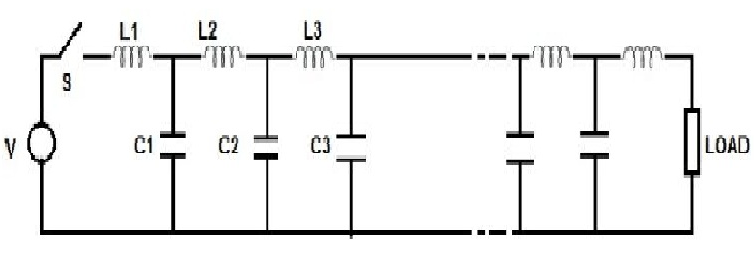
Travelling waves are the current and voltage waves that create a disturbance and moves along the transmission line from the sending end of a transmission line to the other end at a constant speed. The travelling wave plays a major role in knowing the voltages and currents at all the points in the power system. These waves also help in designing the insulators, protective equipment, the insulation of the terminal equipment, and overall insulation coordination.
When the switch is closed at the transmission line's starting end, the voltage will not appear instantaneously at the other end. This is caused by the transient behaviour of inductor and capacitors that are present in the transmission line. The transmission lines may not have physical inductor and capacitor elements but the effects of inductance and capacitance exist in a line. Therefore, when the switch is closed the voltage will build up gradually over the line conductors. This phenomenon is usually called as the voltage wave is travelling from the transmission line's sending end to the other end. And similarly, the gradual charging of the capacitances happens due to the associated current wave.
If the switch is closed at any instant of time, the voltage at load does not appear instantly. The 1st section will charge first and then it will charge the next section. Until and unless a section gets charged the successive section will not be charged .thus this process is a gradual one. It can be realized such that several water tanks are placed connectively and water flows from the 1st tank to the last tank.
The content is sourced from: https://handwiki.org/wiki/Performance_and_modelling_of_AC_transmission
References
- Stephen W. Fardo & Dale R. Patrick, Electrical Power Systems Technology, Third Edition, Taylor & Francis Ltd. ,USA, 2008, ISBN:978-1-4398-0027-0, Chapter 8 Power Distribution Fundamentals
- Electric power systems. Weedy, B. M. (Birron Mathew) (5th ed.). Chichester, West Sussex, UK: John Wiley & Sons, Ltd. 2012. pp. 319. ISBN 9780470682685. OCLC 789661388. http://www.worldcat.org/oclc/789661388
- Padiyar, K. R. (1990). HVDC power transmission systems : technology and system interactions. New York: Wiley. pp. 21. ISBN 0470217065. OCLC 22388689. http://www.worldcat.org/oclc/22388689
- Mehta, V. K., 1944- (2005). Principles of power system : (including generation, transmission, distribution, switchgear and protection). Mehta, Rohit (Writer on Electrical Engineering) (4th ed.). New Delhi: S. Chand. pp. 126. ISBN 8121924960. OCLC 61139348. http://www.worldcat.org/oclc/61139348
- Mehta, V. K., 1944- (2005). Principles of power system : (including generation, transmission, distribution, switchgear and protection). Mehta, Rohit (Writer on Electrical Engineering) (4th. ed.). New Delhi: S. Chand. pp. 159. ISBN 8121924960. OCLC 61139348. http://www.worldcat.org/oclc/61139348
- Mehta, V. K., 1944- (2005). Principles of power system : (including generation, transmission, distribution, switchgear and protection). Mehta, Rohit (Writer on Electrical Engineering) (4th. ed.). New Delhi: S. Chand. pp. 264. ISBN 8121924960. OCLC 61139348. http://www.worldcat.org/oclc/61139348
- El-Hawary, M. E. (1995). Electrical power systems : design and analysis (Rev. print ed.). New York: Institute of Electrical and Electronics Engineers. pp. 92. ISBN 9780470544464. OCLC 557445432. http://www.worldcat.org/oclc/557445432
- J. F. Wilson, Ferranti and the British Electrical Industry, 1864-1930, Manchester University Press, 1988 ISBN:0-7190-2369-6 page 44
- Line-Charging Current Interruption by HV and EHV Circuit Breakers, Carl-Ejnar Sölver, Ph. D. and Sérgio de A. Morais, M. Sc. http://www.ipst.org/TechPapers/2001/IPST01Paper117.pdf
- A Knowledge Base for Switching Surge Transients, A. I. Ibrahim and H. W. Dommel http://www.ipst.org/TechPapers/2005/IPST05_Paper050.pdf
- A Textbook of Electrical Technology, Theraja, ISBN:978-81-219-2440-5 ,SChand & co.
- Forbes T. Brown (2006). Engineering System Dynamics. CRC Press. p. 43. ISBN 978-0-8493-9648-9. https://books.google.com/books?id=UzqX4j9VZWcC&pg=PA43.
- Kenneth L. Kaiser (2004). Electromagnetic Compatibility Handbook. CRC Press. pp. 13–52. ISBN 978-0-8493-2087-3. https://books.google.com/books?id=nZzOAsroBIEC&pg=PT1031.
- "A Brief History of Electromagnetism". http://web.hep.uiuc.edu/home/serrede/P435/Lecture_Notes/A_Brief_History_of_Electromagnetism.pdf.
- CL Wadhwa, Electrical Power Systems, Seventh Multicolour Edition, New Age International (P) Limited , New Delhi, 2017, ISBN:978-93-86070-19-7, Chapter 2 Line Constant Calculations
- "Definition of 'farad'". Collins. http://www.collinsdictionary.com/dictionary/english/farad.
- William D. Greason (1992). Electrostatic discharge in electronics. Research Studies Press. p. 48. ISBN 978-0-86380-136-5. https://books.google.com/books?id=404fAQAAIAAJ. Retrieved 4 December 2011.
- CL Wadhwa, Electrical Power Systems, Seventh Multicolour Edition, New Age International (P) Limited , New Delhi, 2017, ISBN:978-93-86070-19-7, Chapter 3 Capacitance of Transmission Lines
- Ushida, Jun; Tokushima, Masatoshi; Shirane, Masayuki; Gomyo, Akiko; Yamada, Hirohito (2003). "Immittance matching for multidimensional open-system photonic crystals". Physical Review B 68 (15): 155115. doi:10.1103/PhysRevB.68.155115. Bibcode: 2003PhRvB..68o5115U. https://dx.doi.org/10.1103%2FPhysRevB.68.155115
- J. Glover, M. Sarma, and T. Overbye, Power System Analysis and Design, Fifth Edition, Cengage Learning, Connecticut, 2012, ISBN:978-1-111-42577-7, Chapter 5 Transmission Lines: Steady-State Operation
- Gray, §3.2, p. 172
- Jaeger, §10.5 §13.5 §13.8
- Electrical Power Systems: Design and Analysis, Md. E.El-Hawary, ISBN:0-7803-1140X, p.157.
- Ghosh, p.353.
- A. Chakrabarti, p.581, ISBN:81-7700-000-4 ,Dhanpat Rai & Co pvt. ltd.
- A. Chakrabarti, ISBN:81-7700-000-4 ,Dhanpat Rai & Co pvt. ltd.
- NPTEL courses Chapter 2 : Transmission Line Models (https://nptel.ac.in/courses/117104071/chap2.pdf)
- CL Wadhwa, Electrical Power Systems, Seventh Multicolour Edition, New Age International (P) Limited, New Delhi, 2017, ISBN:978-93-86070-19-7, Chapter 2 Performance of Lines
- A.C. Monteith , C.F. Wagner (ed), Electrical Transmission and Distribution Reference Book 4th Edition, Westinghouse Electric Corporation 1950, page 6
- C.L. Wadhwa, Page 62, ISBN:978-93-86070-19-7 , New Age International Pvt. Ltd.
