For Electric Vehicles (EVs), the electric charge of the battery is the main fuel to drive the car. To refuel the EV, we have to connect the EV to a charging station. For the EV charging pile, there are two options are available: (a) AC charging pile and (b) DC charging pile. The dedicated connector standards are used to connect the EV with AC and/or DC charging stations. The specifications of different connector standards are described in detail with pin configuration and comparative discussion.
- AC Connector
- DC Connector
- CHAdeMO
- Combo CCS Connector
1. EV Charging Connector Standards
International organizations have been working for many years to enact their connection standards regarding the high-power charging of EVs. The commonly used technologies are (a) AC on-board charging and (b) DC off-board charging. In previous years, European EV manufacturers have rather produced EVs with on-board chargers which are compatible with a high-power AC supply. However, since the company TEPCO introduced a standard Japanese socket for DC connection, namely CHAdeMO, DC off-board charging is becoming more common. CHAdeMO is now available in several European countries, and although it is not internationally standardized yet, it is widely used in the US and Japan[1]. The SAE also has been developing its own connector standard called Combo. In SAE J1772, the Combo coupler features extra pins compared to the standard version[2].
1.1. AC Charging Connector
The IEC 62196-2 standard defines three types of connectors for AC supply power in Europe. These types of connectors are described in Table 1.
Table 1. IEC 62196-2 Connector Standard for AC charging[3].
IEC 62196-2 |
Type 1 |
Type 2 |
Type 3 |
|
Coupler |
1-phase |
1-phase and 3-phase |
1-phase and 3-phase with shutters |
|
Related standard |
SAE J1772 Type 1 |
VDE-AR-E 26232-2 |
- |
|
Maximum current |
32 A (80 A at the US) |
70 A (1-phase) 63 A (3-phase) |
16 A (1-phase) 32 A (3-phase)/63 A(3-phase) |
|
Maximum voltage |
250 V |
480 V (3-phase) |
250 V/400 V |
|
Maximum power |
19 kW |
43.5 kW |
22 kW (3-phase) |
|
Pin and interlock |
5 pins, mechanic lock |
7 pins, electronic lock |
4 pins or 5 pins |
|
Control pin |
Two short pins |
One short, one long pin |
- |
|
Communication |
PWM over CP |
PWM over CO |
- |
|
|
|
|
|


The IEC 62196-2 Type 1 is not different compared to the SAE J1772 which is widely used in the US and Japan. In China, the IEC 62196-2 Type 1 is also known as GB/T 20234.2-2015 connector. Notice that China has modified it by changing it from an electronic lock into a mechanic lock (with the option of an electronic lock) and the control pilot is using two short pins.
1.2. DC Charging Connector
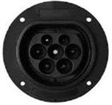
The most common use of fast charging technologies is to supply direct current to the EV battery. This requires an off-board charging station to supply high levels of current and to transform the AC of the distribution grid to DC for the charging of the EV’s battery. CHAdeMO was the first fast-charging method in the world, specified by the Japan Electric Vehicle Standard (JEVS) G105-1993 from the JARI (Japan Automobile Research Institute), and it has been developed by the Japanese company TEPCO. CHAdeMO is an abbreviation of “CHArge de MOve” or “move by charge”[4]. The connector includes two large pins for DC power, plus other pins to carry CAN-BUS connections. The CHAdeMO transmits the information by CAN-BUS and analog control lines. This hybrid communication protocol has more advantages compared to pure digital control since it can let the system double-check the digital control system. Once the analog signal is lost, an immediate charging operation shutdown can be performed [28]. The CHAdeMO specifications comply with the international standard IEC 62196-3. The characteristics of CHAdeMO are shown in Table 2.
Table 2. CHAdeMO connector characteristics[5].
|
Parameter Description |
Rated Values |
|
|
Maximum current |
120 A |
|
|
Maximum voltage |
500 V DC |
|
|
Maximum power |
50 kW |
|
|
Maximum current (control system) |
7 A |
|
|
Maximum voltage (control system) |
12 V DC |
|
|
Level of charging |
DC level 3 |
|
|
Control pin |
7 pins |
|
|
Communication protocol |
CHAdeMO (CAN communication) |
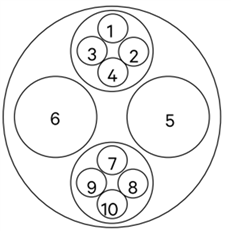
The configuration of CHAdeMO only specifies the necessary and effective parts for connection. A summary and pinout of CHAdeMO are shown in Table 3.
Table 3. CHAdeMO pinout functionalities[6].
|
Pin ID |
Wire Cross Section (mm2) |
Description |
|
|
1 |
0.75 |
Ground |
|
|
2 |
0.75 |
Start/stop charging 1 |
|
|
3 |
|
None |
|
|
4 |
0.75 |
Permission/prohibition charging |
|
|
5 |
22 or 40 |
DC supply negative |
|
|
6 |
22 or 40 |
DC supply positive |
|
|
7 |
0.75 |
Verification of the connector connection |
|
|
8 |
0.75 |
CAN High |
|
|
9 |
0.75 |
CAN Low |
|
|
10 |
0.75 |
Start/stop charging 2 |
1.3. Combined Charger Connector (J1772-2009 Combo)
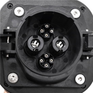
In parallel to CHAdeMO, the US and some European EV manufacturers such as Audi, BMW, Daimler, Ford, General Motors, Porsche, or Volkswagen have been developing a new system for fast charging: the Combined Charging System (CCS), i.e., J1772-2009 Combo. The main goal of this standard is to allow the EV to charge in both AC (slow/medium charging) and DC (fast charging), which is different from CHAdeMO as it only allows DC and needs an extra socket for AC charging.
There are two types of Combo CCS currently available. The Combo Type 1 connector for the US has been developed based on the AC Type 1 connector (specified by the standards SAE J1772/UNE EN 62196-2). The Combo Type 2 for Europe integrates a Type 2 connector as defined in the standard UNE EN 62196-2[7]. The main characteristics of Combo connectors Type 1 and Type 2 are summarized in Table 4.
Table 4. Main characteristics of Combo connectors Type 1 and type 2[5].
|
Parameters |
Combo Type 1 (US) |
Combo Type 2 (EU) |
|
|
|
|
DC Charging |
||
|
Maximum current |
150 A |
200 A |
|
Maximum voltage |
600 V |
850 V |
|
Charging mode |
4 |
4 |
|
Maximum power |
90 kW |
170 kW |
|
Connector type |
Combo 1 (IEC 62196-3) |
Combo 2 (IEC 62196-3) |
AC Charging |
||
|
Nominal current |
32 A |
70 A (1-phase)/63 A (3-phase) |
|
Nominal voltage |
250 V |
230 V (1-phase)/400 V (3-phase) |
|
Charging mode |
3 |
3 |
|
Maximum power |
13 kW |
44 kW |
|
Connector type |
Type 1 (IEC 62196-2, SAE J1772) |
Type 2 (IEC 62196-2) |

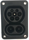
The Combo Type 1 and Type 2 have different pinout configurations based on their different functionalities. Table 5 shows the configuration and the functions of the pins in Combo Type 1 and Type 2.
Table 5. The pin configuration and functionality of Combo connectors Type 1 and Type 2[6].
|
Pin |
Functions |
Comments |
Combo Type 1 |
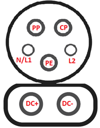
|
PP |
Communication/Charging process control |
Proximity inlet |
|
|
CP |
Control pilot |
||
|
PE |
Earth ground |
EV to earth ground |
|
|
L1/N |
AC 1-phase charging |
Phase 1/Neutral |
|
|
L2 |
Phase 2 |
||
|
DC+ |
DC charging |
DC positive terminal |
|
|
DC- |
DC negative terminal |
||
|
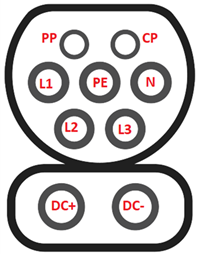
Pin |
Functions |
Comments |
Combo Type 2 |
|
PP |
Communication/Charging process control |
Proximity inlet |
|
|
CP |
Control pilot |
||
|
PE |
Earth ground |
EV to earth ground |
|
|
L1 |
AC 3-phase Charging |
Phase 1 |
|
|
L2 |
Phase 2 |
||
|
L3 |
Phase 3 |
||
|
N |
Neutral |
||
|
DC+ |
DC Charging |
DC positive terminal |
|
|
DC- |
DC negative terminal |
Currently, GB/T was giving just 237.5 kW at 950 V and 250 A; thus, this will be about four times more competent in terms of power than other DC charging connectors. Power will be more than twice as high as the new 400 kW CHAdeMO and 350 kW CCS Combo specs, too. However, the V2G features are not supported by GB/T connector standard. The feature comparison among the DC charging connector standards is listed Table 6 below:
Table 6. Specification comparison of different DC charging connector standards[7].
|
Specification |
New GB/T |
GB/T |
CHAdeMO |
CCS Type 1 |
Tesla |
|
|
|
|
|
|
|
|
Max Power |
900 kW |
237.5 kW |
400 kW |
400 kW |
135 kW |
|
No. of Control Pilot |
2 |
0 |
3 |
1 |
1 |
|
Communication |
CAN (SAE J1939) |
CAN (SAE J1939) |
CAN (ISO 11898) |
PLC (ISO 15118) |
CAN (SAE J2411) |
|
+12 V Power Supply |
Yes |
Optional |
Yes |
No |
No |
|
V2G Compatible |
Unknown |
Under R&D |
Yes |
Under R&D |
No |
|
Coupler Lock |
Inlet |
Connector |
Connector |
Inlet |
Inlet |
|
Availability |
China |
China, India |
Global |
EU, US, A |
Global |
|
Related Standards |
IEC 61851-23-1 IEC 61851-23-2 |
IEC 61851-23-1 |
IEC 61851-23-1 IEC 61851-23-2 IEEE 2030.1 |
IEC 61851-23-1 SAE J1772 |
None |
|
Cooling Technique |
Liquid-Cooled Cable Under Development |
Liquid-Cooled Cable Not Available |
Liquid-Cooled Cable Under Development |
Liquid-Cooled Cable Under Development |
Liquid-Cooled Cable Discontinued |


References
- M. D. Yoshida and T. Blech. ”CHAdeMO DC Charging: Successful Transition Towards Nation- and Region-Wide Ze-ro-Emisson”. CHAdeMO association, April 2021. Available online: https://movelatam.org/portfolio-item/chademo-charging-protocol-for-electric-vehicles/ (accessed on 24 July 2022).
- Myles, B., & Robert, E. , " Making the right connections General procurement guidance for electric vehicle charge points," 2015. [Online]. Available: http://ukevse.org.uk/resources/procurement-guidance/.
- Luyten, Leemput, N., Geth, F., Van Roy, J., Büscher, J., & Driesen, J. (2013). Standardization of Conductive AC Charging Infrastructure for Electric Vehicles. In IET Conference Publications (Vol. 2013, Issue 615 CP). https://doi.org/10.1049/cp.2013.0751
- Schwarzer, V.; Ghorbani, R. Current State-of-the-Art of EV Chargers; EVTC Electric Vehicle Transportation Centre: Cocoa, FL, USA, 2015; pp. 1–13.
- Quílez, M.G.; Abdel-Monem, M.; El Baghdadi, M.; Yang, Y.; Van Mierlo, J.; Hegazy, O. Modelling, analysis and performance evaluation of power conversion unit in G2V/V2G application-a review. Energies 2018, 11, 1082.
- Cuma, M.U.; Tümay, M.; Yirik, E.; Ünal, E.; Dericioğlu, Ç.; Onur, B. A review of charging technologies for commercial electric vehicles. Int. J. Adv. Automot. Technol. 2018, 2, 61–70.
- “China is Developing New GB/T Fast Charging Standard at 900kW”. Insideevs Press Release, 19 Jun 2018. Available Online: https://insideevs.com/news/338620/china-is-developing-new-gb-t-fast-charging-standard-at-900-kw (accessed on 29 Septem-ber 2022).