Your browser does not fully support modern features. Please upgrade for a smoother experience.
Please note this is an old version of this entry, which may differ significantly from the current revision.
Holographic optical tweezers (HOT) is a programmable technique used for manipulation of microsized samples. In combination with computer-generation holography (CGH), a spatial light modulator reshapes the light distribution within the focal area of the optical tweezers. HOT can be used to realize real-time multiple-point manipulation in fluid, and this is useful in biological research.
- optical tweezers
- holographic optical tweezers
- holographic tomography
- computer-generated hologram
1. Introduction
Optical tweezers (OT) [1] utilize a highly focused laser beam to manipulate a microscale-to-nanoscale [2][3] particle or single atom [4]. The particles in Brownian motion are restricted within the focal region because of the intensity gradient change and momentum transfer. For decades, optical tweezers have been widely used in biological research [5][6][7][8] to detect biological samples, using suitable wavelengths, without damaging them. Based on particle size, two theoretical models are used for force analysis—the ray optics model [9] for microsized particles and the Rayleigh model [10] for nanosized particles. This research focuses on biological cells or bacteria within the ray optics regime.
2. HOT Technique for Bio-Application
In biological research, fluid environments and the presence of diverse components usually increase the complexity of measurement and limit its accuracy. This issue can be addressed by rearranging microparticles at design points, using HOT, enabling long-term observation or further applications without physical contact. Thus, it serves as a powerful tool in fluid microenvironments. The advantages and characteristics of HOT for bioapplications are summarized in Figure 1.
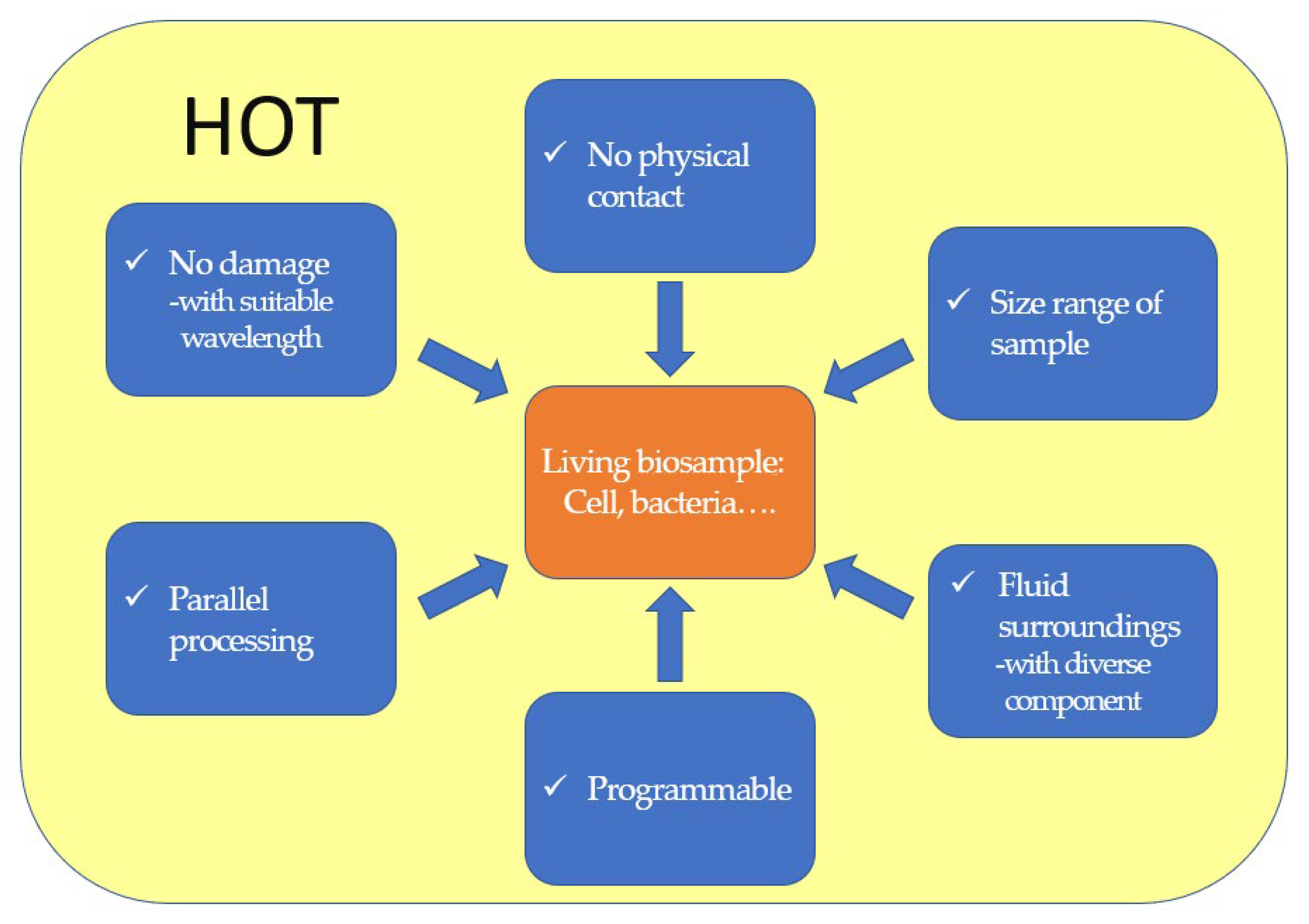
Figure 1. The advantages and characteristics of HOT in bio-applications.
In this section, the researchers summarize the bio-applications of HOT. As depicted in Figure 2, HOT provides the functions of multiple spots’ manipulation and orientation control. The multiple spot manipulations can be used to guide and assemble bio-samples for further applications, such as bio-fabrication for micro-robots, micro-tools, and microstructures; moreover, the orientation control can increase the potential of design. HOT can also extend the parallel ability of detection systems to sustain the studied organelles within the sample on the same plane. Finally, HOT can also be used to control biological sample orientations to aid detection systems, such as DHM, in studying cellular mechanics.
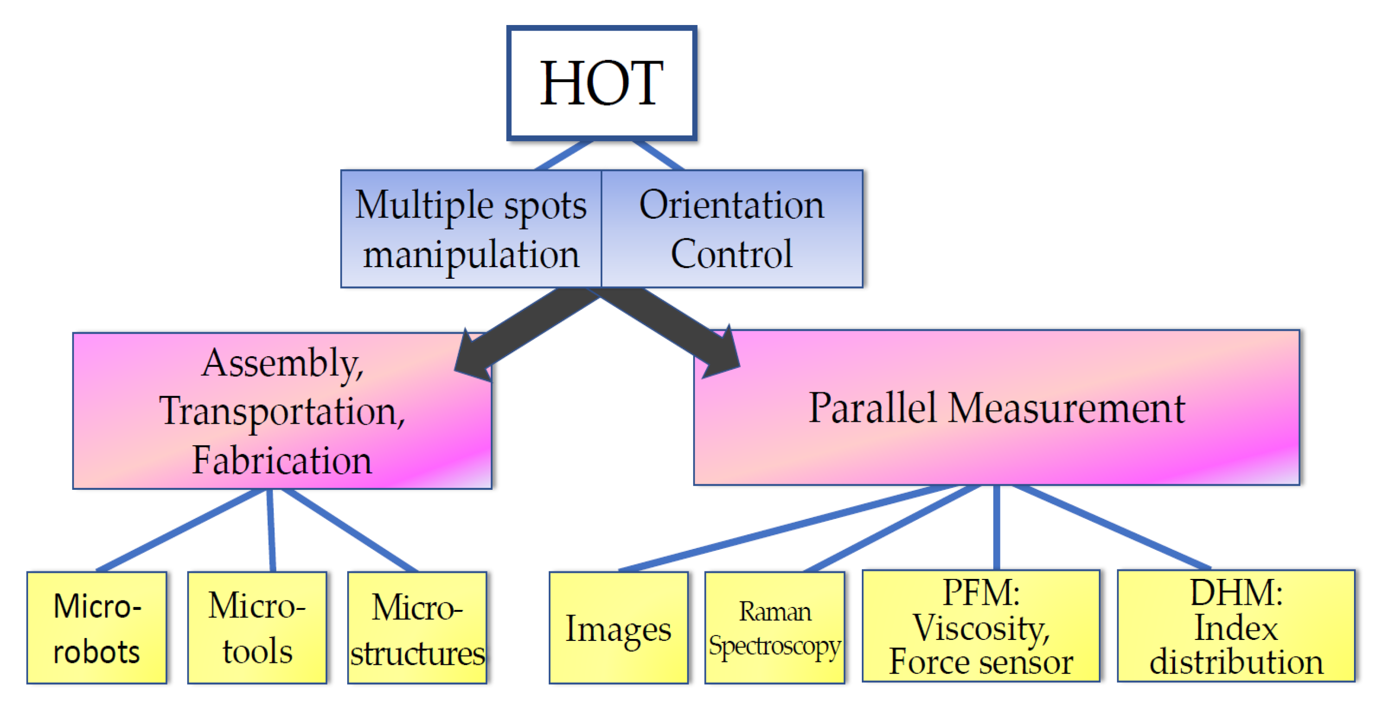
Figure 2. Bio-applications of HOT.
2.1. Assembly and Bio-Structure Fabrication
HOT can be used to program the assembly of nano- and microsized particles [11][12] into crystal growths [13] or microstructures [14]. Several research groups have verified the feasibility of HOT-driven in 3D space. Padgett et al. [11][15] lined up several silica spheres and then moved them into a 3D structure. They also constructed 3D crystal templates for photonic bandgap materials [16] by using microspheres ranging from 0.8 to 3 μm. Other studies [17][18] have reported the assembly of microsized particles into crystalline photonic heterostructures.
On the other hand, Dufresne et al. [12] adopted real-time feature recognition to automate the assembly and sorting of colloidal silica by size. Subsequently, Shaw et al. [19] improved the throughput of automation via efficient path planning and particle identification. The assembly technique can be extended to crystal growth and fabrication [13] by combining it with a fixing process, such as polymerization [20][21].
The assembly function of HOT is also suitable for microfluidic cytometry and lab-on- a-chip devices [22][23][24]. Akselrod et al. [24] were the first to assemble living bacteria into the designing 2D and 3D arrangements in hydrogels without losing viability. Later, Leach et al. [25] arranged the live embryonic stem cells of mice along straight lines, curves, and circles and studied the interaction between multiple bio-samples. Using a suitable gelatin medium, Jordan et al. [26] and Mirsaidov et al. [27] created permanent 3D arrangements of isolated E. coli. The fabricated structures remained intact, and the E. coli survived for several days even after removing the laser beam. However, the aforementioned bio-sample matrix array is insufficient to study the bio-system. The surrounding microenvironment also affects system operation. Even in this context, HOT can be used to assemble biological structures and manufacture complex cellular structures accurately [28][29].
Additionally, HOT has been applied to the fields of micro-robotics and micro-tools. Barroso et al. [30] employed HOT to fabricate living micro-robots comprising a rod-shaped prokaryotic bacterium and a single elongated zeolite L crystal. As depicted in Figure 3, HOT controls the orientation of zeolite L crystal and the position of bacterium and then assembles them together. After the trapping laser is turned off, the bacterium–zeolite L living machine can swim itself by using the bacterium’s flagella. Unlike the aforementioned studies that used mobile bacteria for transport, Sun et al. focused on automatically transporting [31][32][33][34] by moving laser spots. They fabricated a micro-tool to transport biological cells indirectly. Figure 4 depicts the design of the micro-tool and the transportation results. Three trapping spots generated via HOT are used to manipulate the position and orientation of the micro-tool and transport the biological cell. Three-spots tweezers trap the micro-tool and indirectly move the cell along the designed path (dash line) to the desired position. The images during transportation are shown in Figure 4a–d.
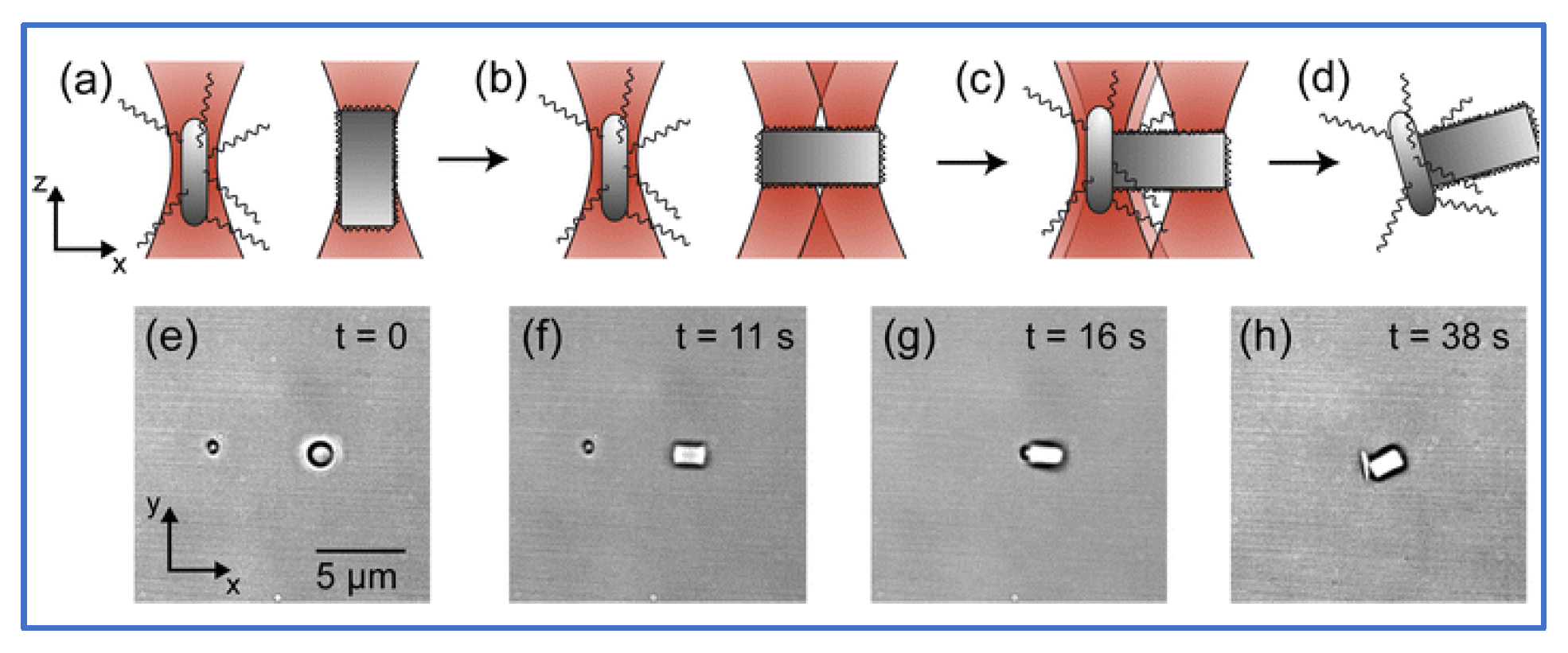
Figure 3. Optical assembly of bio-hybrid micro-robot [30]. (a) HOTs trap bacterium and zeolite L crystal. (b) The orientation of zeolite L crystal is rotated by a two-spots HOT. (c) HOT assembles them together. (d) Trapping laser is turn off, then bacterium–zeolite L living machine utilizes the bacterium’s flagella to swim on its own. (e–h) Top views of the experiment during the assembling process (a–d).
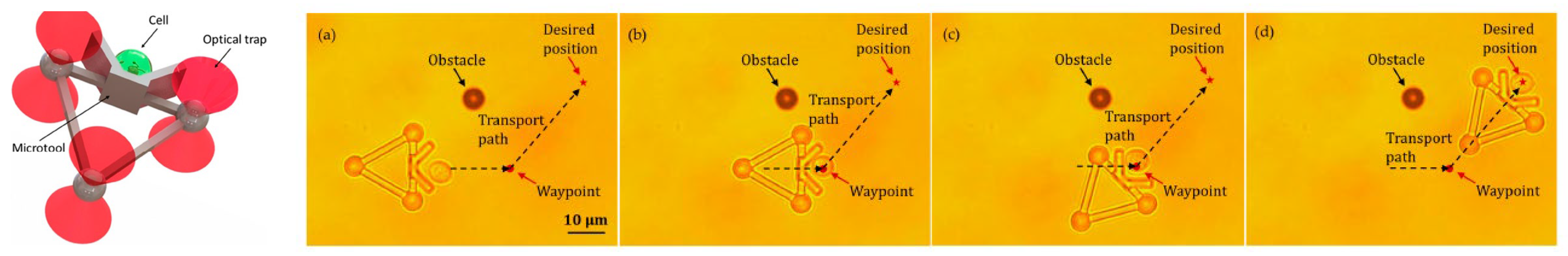
Figure 4. The indirect transportation of biological cells with HOT [34]. (a) Three-spots HOTs trap and move the microtool. The microtool push the cell. (b) The cell is carried to the waypoint to avoid the obstacle. (c) The moving direction of the microtool is redirected to the desired position. (d) Cell is transported to the desired location.
2.2. Parallel Measurement of the Bio-Samples in a Fluid
HOT can be used to sustain multiple sample positions in a fluid, enabling parallel measurement and study of a single cell [35]. For instance, fluorescence microscopy can be used to acquire image stacks to extract quantitative data with high spatial and temporal protein distributions. Eriksson et al. [36] combined 3D CGH, HOT, and image analysis to optimize the axial position of trapped cells in an array. As depicted in Figure 5a,c, via 2D optical trapping, all trapping points are aligned on the same plane. To obtain better images of all nuclei, their automated system displaced the nuclei onto a single imaging plane (Figure 5b,d), and a greater number of images could be obtained via time-lapse experiments before photobleaching. HOT can also be used to increase the parallel processing capability of digital holographic microscopy. Kemper et al. [37] aligned several bacterial cells precisely on the surface of living host cells by using HOT and simultaneously monitored them via self-interference digital holographic microscopy. Their system enables the 3D modeling and imaging of infection scenarios on the single-cell level.
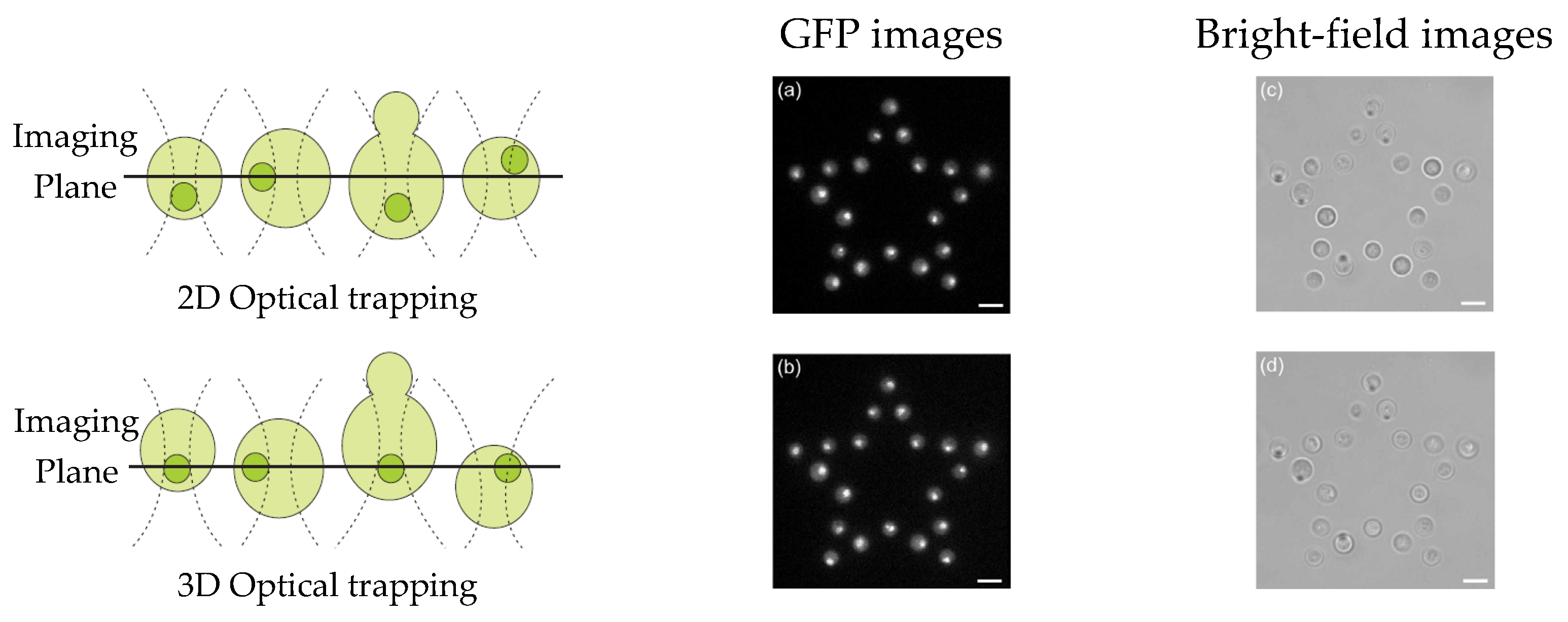
Figure 5. Automated focusing for nuclei of multiple cells [36]: (a,b) GFP images, (c,d) bright-field images, (a,c) trapping points on the same plane, and (b,d) nuclei on the same plane.
The incorporation of HOT also enhances the performance of Raman spectroscopy [38][39]. Raman spectroscopy [40] can be used to probe the biochemical composition of microorganisms without preprocessing. However, the floating motion of motile microbial samples influences the temporal and spatial resolution of the Raman signal. By integrating it with optical trapping, Raman tweezers [41][42] enable the spectroscopic study of the optically immobilized single microorganism under animate conditions [43]. Parlatan et al. [44] sorted and transported yeast cells and polystyrenes by using Raman tweezers. Initially, HOT was used to trap eight particles, and the Raman spectra of the particles were obtained via spectroscopy. From the spectral results, polystyrene particles and yeast cells were identified. The HOT then transported the polystyrene particles away.
OT can also be applied in photonic force microscopy (PFM) [45] to measure forces in the pico-Newton range by detecting the Brownian motion of single trapped samples. This enables the study of the viscoelasticity of the bio-sample. The use of CGH enhances the dynamic control ability and lets HOT manipulate the movement of beads in vivo. For instance, Hörner et al. [46] injected fluorescent beads into zebrafish embryos and then applied HOT to control the movement of the beads in vivo to investigate the viscoelastic properties of the embryos, enabling the study of embryonic development without invasive intervention.
Moreover, the incorporation of CGH enables the simultaneous study of multiple cells or molecules by using PFM. Mejean et al. [47] measured the mechanical coupling between an Aplysia growth cone and a bead functionalized with the neuronal cell adhesion molecule, apCAM. As depicted in Figure 6, HOT was used to position several beads near the leading edge of the growth cone—subsequently, the cell pulled the beads, which escaped from the optical force. Cell adhesion and related motility were then measured. HOT can also be applied to the measurement of the viscoelasticity of proteins and membranes [48]. In this case, the ends of the extended molecule stick to the particles, and then the particle is manipulated by HOT to measure the relation between the force and the particles’ separation. Uhrig et al. [49] demonstrated this application in a microfluidic environment. As illustrated in Figure 8, they constructed a biomimetic quasi-two-dimensional actin network on an array of polystyrene microspheres trapped inside a microfluidic chamber. Then they studied chemo-mechanical processes via force measurement. As depicted in Figure 8, Streichfuss et al. [50] also programmed three spot locations and used them to measure forces between two single actin filaments during bundle formation.
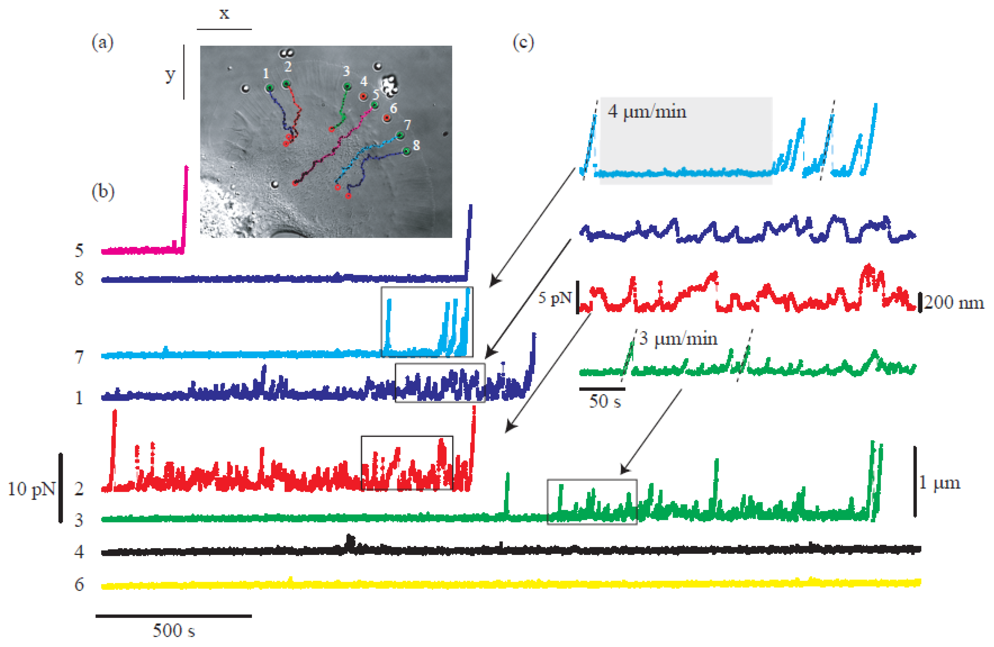
Figure 6. Growth cone study of base on multiple force measurement [47]. (a) HOT hold the position of beads near the leading edge of the growth cone. (b,c) The force measured when the cell pulls the bead.
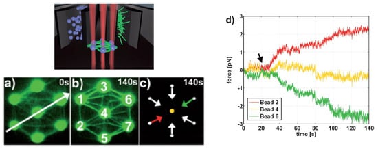
Figure 7. Actin network construction and optical force sensor array [49]. (a–c) A constructed biomimetic quasi-two-dimensional actin network. (d) Measuring force on beads with HOT.
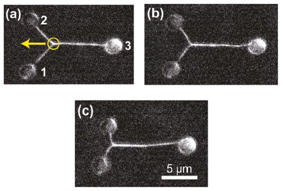
Figure 8. Two single actin filaments during bundle formation [50]. (a–c) Sequential fluorescence images of the bunding filaments. Yellow circle indicates the attachment between filaments, yellow arrow indicates the bunding axis.
2.3. Digital Hologram
Digital holography microscopy (DHM) [51][52][53][54] is a label-free optical microscopic imaging system which is suitable for the study of biological samples study [55][56]. The computer program can numerically reconstruct the quantitative refractive index (RI) distribution inside bio-samples by digitally recording the interference pattern as a hologram. OT can rotate the orientation of the sample to a specified angle to gather part of the sample’s information. Bernecker et al. [57] measured the RI distribution for RBCs (red blood cells) from two perspective angles—when the long axis lies on the slide and when it is rotated by the OT to perpendicular to the slide. This application is extended to real 3D imaging in holographic tomography [58][59][60][61][62], which employs beam-rotation [63][64] or sample-rotation schemes [62][65][66][67][68] to scan entire samples under the different angles of illumination and calculate the integral phase. The beam-rotation method can be implemented by using a galvano-mirror, LCD, or digital micro-mirror device (DMD), which keeps the sample and the observation system static. The beam-rotation method exhibits a limited measuring angle, leading to an anisotropic resolution with incomplete spatial frequency coverage [69][70]. However, the sample-rotation method retains an illumination system with better reconstruction features.
Among the multiple techniques used for sample rotation, HOT offers an all-optical setup [66][67][68][71][72] with stable control and exhaustive measuring angles. Habaza et al. [68] applied the HOT technique to rotate samples during recording processing in tomography-phase microscopy. They utilized a two-spot trap to orient a yeast cell on the y–z plane over 180° in angular steps of 5° and captured the off-axis interferogram at each stage. The researchers' team [66][67] also proposed a two-spot trap to implement full-angle rotation for living yeast cells and Candida rugosa in a fluid and acquired an entire symmetric spectrum for tomography reconstruction. Figure 9 depicts the HT-HOT joint system. Green laser light with 2D-GSA CGH information was used to illuminate the sample area to hold the sample and rotate its orientation. The HT system was built up by using the red laser, and the 3D-RI distribution of the sample was recorded.
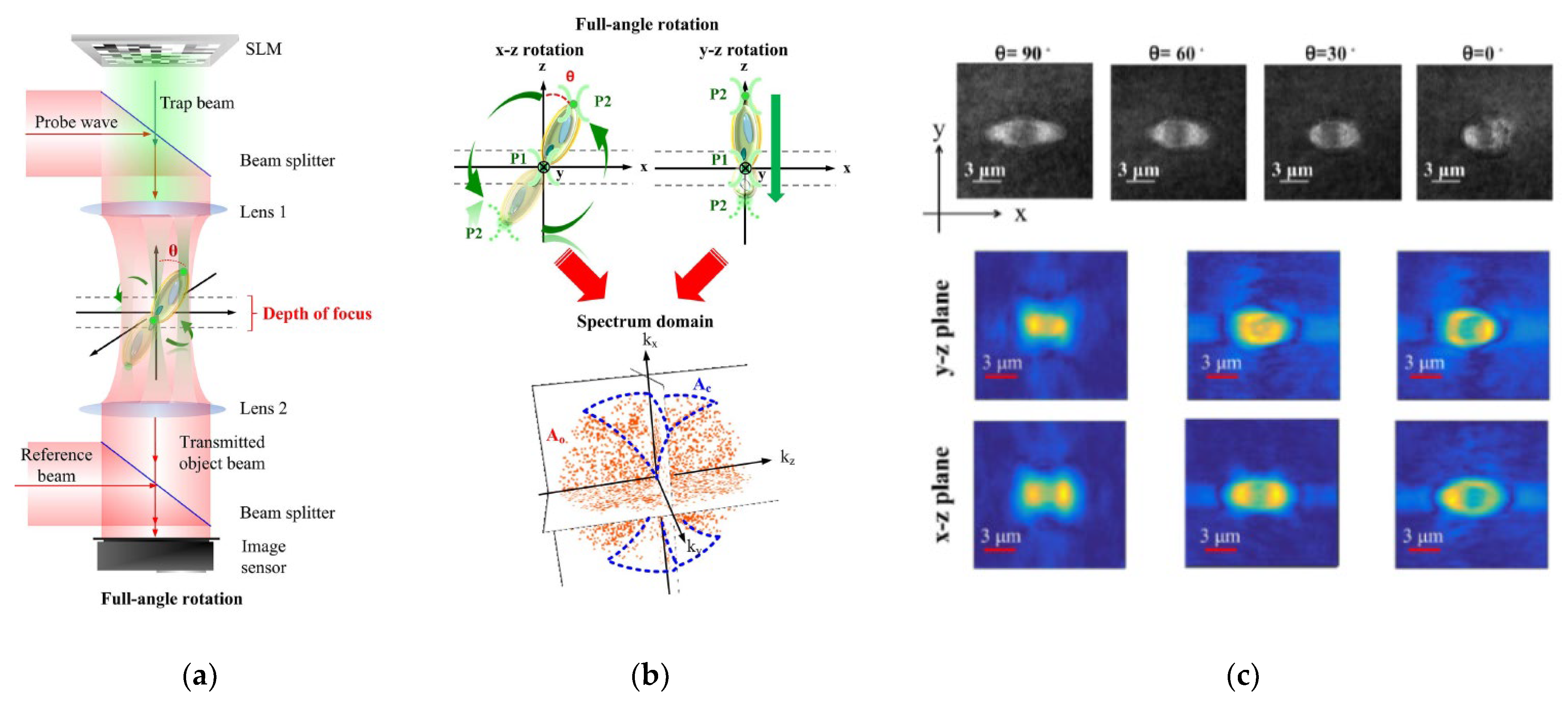
Figure 9. HT-HOT joint system [66]. (a) Optical system. (b) The schematic diagram. (c) The measuring index distributions of yeast cell.
To extend the application of HOT and DHM to arbitrarily shaped samples, Park et al. proposed the tomographic molds for optical trapping (TOMOTRAP) [71][72]. Initially, their system measured the 3D-RI distributions of the samples. Then, based on them, they applied a 3D-GSA to generate a continuous light field distribution for the optical trapping. This 3D reconstructed beam intensity distribution is identical to the sample volume and can be used to manipulate the sample. They demonstrated orientation control, folding, and assembly of RBCs and eukaryotic cells [71]. They recently developed isotropically resolved label-free tomographic imaging based on tomographic molds for optical trapping [72]. As illustrated in Figure 10, their proposed method yields an isotropic resolution of 230 nm and captures the structural details of live RBCs.
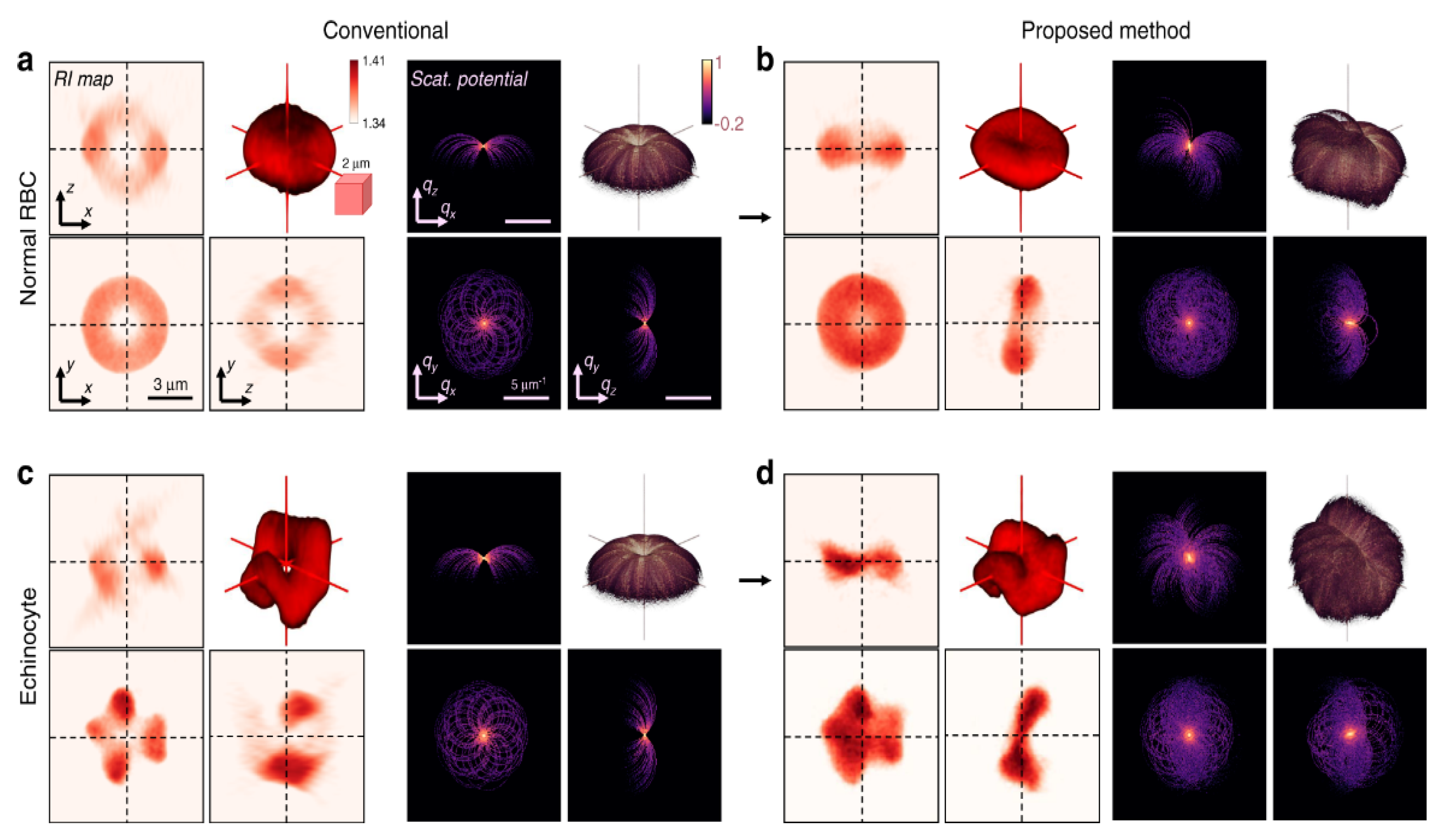
Figure 10. 3D refractive index reconstruction [72] of (a,b) normal RBCs and (c,d) echinocyte, by (a,c) conventional optical diffraction tomography and (b,d) TOMOTRAP system.
This entry is adapted from the peer-reviewed paper 10.3390/app122010244
References
- Ashkin, A.; Dziedzic, J.M.; Bjorkholm, J.E.; Chu, S. Observation of a single-beam gradient force optical trap for dielectric particles. Opt. Lett. 1986, 11, 288–290.
- Bradac, C. Nanoscale Optical Trapping: A Review. Adv. Opt. Mater. 2018, 6, 1800005.
- Kolbow, J.D.; Lindquist, N.C.; Ertsgaard, C.T.; Yoo, D.; Oh, S.H. Nano-Optical Tweezers: Methods and Applications for Trapping Single Molecules and Nanoparticles. ChemPhysChem 2021, 22, 1409–1420.
- Samoylenko, S.R.; Lisitsin, A.V.; Schepanovich, D.; Bobrov, I.B.; Straupe, S.S.; Kulik, S.P. Single atom movement with dynamic holographic optical tweezers. Laser Phys. Lett. 2020, 17, 8.
- Svoboda, A.K.; Block, S.M. Biological Applications of Optical Forces. Annu. Rev. Biophys. Biomol. Struct. 1994, 23, 247–285.
- Wang, M.D. Manipulation of single molecules in biology. Curr. Opin. Biotechnol. 1999, 10, 81–86.
- Xin, H.; Li, Y.; Liu, Y.-C.; Zhang, Y.; Xiao, Y.-F.; Li, B. Optical Forces: From Fundamental to Biological Applications. Adv. Mater. 2020, 32, 2001994.
- Favre-Bulle, I.A.; Stilgoe, A.B.; Scott, E.K.; Rubinsztein-Dunlop, H. Optical trapping in vivo: Theory, practice, and applications. Nanophotonics 2019, 8, 1023–1040.
- Ashkin, A. Forces of a single-beam gradient laser trap on a dielectric sphere in the ray optics regime. Biophys. J. 1992, 61, 569–582.
- Ashkin, A. Trapping of Atoms by Resonance Radiation Pressure. Phys. Rev. Lett. 1978, 40, 729–732.
- Sinclair, G.; Jordan, P.; Courtial, J.; Padgett, M.; Cooper, J.; Laczik, Z.J. Assembly of 3-dimensional structures using programmable holographic optical tweezers. Opt. Express 2004, 12, 5475–5480.
- Chapin, S.C.; Germain, V.; Dufresne, E.R. Automated trapping, assembly, and sorting with holographic optical tweezers. Opt. Express 2006, 14, 13095–13100.
- Leach, J.; Sinclair, G.; Jordan, P.; Courtial, J.; Padgett, M.J.; Cooper, J.; Laczik, Z.J. 3D manipulation of particles into crystal structures using holographic optical tweezers. Opt. Express 2004, 12, 220–226.
- Gould, O.E.C.; Qiu, H.B.; Lunn, D.J.; Rowden, J.; Harniman, R.L.; Hudson, Z.M.; Winnik, M.A.; Miles, M.J.; Manners, I. Transformation and patterning of supermicelles using dynamic holographic assembly. Nat. Commun. 2015, 6, 7.
- Korda, P.; Spalding, G.C.; Dufresne, E.R.; Grier, D.G. Nanofabrication with holographic optical tweezers. Rev. Sci. Instrum. 2002, 73, 1956–1957.
- Benito, D.C.; Carberry, D.M.; Simpson, S.H.; Gibson, G.M.; Padgett, M.J.; Rarity, J.G.; Miles, M.J.; Hanna, S. Constructing 3D crystal templates for photonic band gap materials using holographic optical tweezers. Opt. Express 2008, 16, 13005–13015.
- Roichman, Y.; Grier, D.G. Holographic assembly of quasicrystalline photonic heterostructures. Opt. Express 2005, 13, 5434–5439.
- Ovanesyan, Z.; Pudasaini, P.R.; Gangadharan, A.; Marucho, M. Three-dimensional quasicrystalline photonic material with five-fold planar symmetry for visible and infrared wavelengths by holographic assembly of quasicrystalline photonic heterostructures. Opt. Mater. Express 2013, 3, 1332–1337.
- Shaw, L.A.; Chizari, S.; Hopkins, J.B. Improving the throughput of automated holographic optical tweezers. Appl. Opt. 2018, 57, 6396–6402.
- Jordan, P.; Clare, H.; Flendrig, L.; Leach, J.; Cooper, J.; Padgett, M. Permanent 3D microstructures in a polymeric host created using holographic optical tweezers. J. Mod. Opt. 2004, 51, 627–632.
- Shaw, L.A.; Chizari, S.; Panas, R.M.; Shusteff, M.; Spadaccini, C.M.; Hopkins, J.B. Holographic optical assembly and photopolymerized joining of planar microspheres. Opt. Lett. 2016, 41, 3571–3574.
- Pagliara, S.; Schwall, C.; Keyser, U.F. Optimizing Diffusive Transport Through a Synthetic Membrane Channel. Adv. Mater. 2013, 25, 844–849.
- Padgett, M.; Di Leonardo, R. Holographic optical tweezers and their relevance to lab on chip devices. Lab Chip 2011, 11, 1196–1205.
- Akselrod, G.M.; Timp, W.; Mirsaidov, U.; Zhao, Q.; Li, C.; Timp, R.; Timp, K.; Matsudaira, P.; Timp, G. Laser-guided assembly of heterotypic three-dimensional living cell microarrays. Biophys. J. 2006, 91, 3465–3473.
- Leach, J.; Howard, D.; Roberts, S.; Gibson, G.; Gothard, D.; Cooper, J.; Shakesheff, K.; Padgett, M.; Buttery, L. Manipulation of live mouse embryonic stem cells using holographic optical tweezers. J. Mod. Opt. 2009, 56, 448–452.
- Jordan, P.; Leach, J.; Padgett, M.; Blackburn, P.; Isaacs, N.; Goksor, M.; Hanstorp, D.; Wright, A.; Girkin, J.; Cooper, J. Creating permanent 3D arrangements of isolated cells using holographic optical tweezers. Lab Chip 2005, 5, 1224–1228.
- Mirsaidov, U.; Scrimgeour, J.; Timp, W.; Beck, K.; Mir, M.; Matsudaira, P.; Timp, G. Live cell lithography: Using optical tweezers to create synthetic tissue. Lab Chip 2008, 8, 2174–2181.
- Dinu, C.Z.; Chakrabarty, T.; Lunsford, E.; Mauer, C.; Plewa, J.; Dordick, J.S.; Chrisey, D.B. Optical manipulation of microtubules for directed biomolecule assembly. Soft Matter 2009, 5, 3818–3822.
- Kirkham, G.R.; Britchford, E.; Upton, T.; Ware, J.; Gibson, G.M.; Devaud, Y.; Ehrbar, M.; Padgett, M.; Allen, S.; Buttery, L.D.; et al. Precision Assembly of Complex Cellular Microenvironments using Holographic Optical Tweezers. Sci. Rep. 2015, 5, 7.
- Barroso, A.; Landwerth, S.; Woerdemann, M.; Alpmann, C.; Buscher, T.; Becker, M.; Studer, A.; Denz, C. Optical assembly of bio-hybrid micro-robots. Biomed. Microdevices 2015, 17, 8.
- Hu, S.Y.; Sun, D. Automated Transportation of Single Cells Using Robot-Tweezer Manipulation System. JALA J. Assoc. Lab. Autom. 2011, 16, 263–270.
- Chen, H.Y.; Wang, C.; Li, X.J.; Sun, D. Transportation of Multiple Biological Cells Through Saturation-Controlled Optical Tweezers In Crowded Microenvironments. IEEE-ASME Trans. Mechatron. 2016, 21, 888–899.
- Hu, S.Y.; Chen, S.X.; Chen, S.; Xu, G.; Sun, D. Automated Transportation of Multiple Cell Types Using a Robot-Aided Cell Manipulation System With Holographic Optical Tweezers. IEEE-ASME Trans. Mechatron. 2017, 22, 804–814.
- Hu, S.Y.; Xie, H.; Wei, T.Y.; Chen, S.X.; Sun, D. Automated Indirect Transportation of Biological Cells with Optical Tweezers and a 3D Printed Microtool. Appl. Sci. 2019, 9, 15.
- Ramser, K.; Hanstorp, D. Optical manipulation for single-cell studies. J. Biophotonics 2010, 3, 187–206.
- Eriksson, E.; Engstrom, D.; Scrimgeour, J.; Goksor, M. Automated focusing of nuclei for time lapse experiments on single cells using holographic optical tweezers. Opt. Express 2009, 17, 5585–5594.
- Kemper, B.; Barroso, A.; Woerdemann, M.; Dewenter, L.; Vollmer, A.; Schubert, R.; Mellmann, A.; von Bally, G.; Denz, C. Towards 3D modelling and imaging of infection scenarios at the single cell level using holographic optical tweezers and digital holographic microscopy. J. Biophotonics 2013, 6, 260–266.
- Creely, C.M.; Volpe, G.; Singh, G.P.; Soler, M.; Petrov, D.V. Raman imaging of floating cells. Opt. Express 2005, 13, 6105–6110.
- Zhang, P.; Kong, L.; Setlow, P.; Li, Y.-q. Multiple-trap laser tweezers Raman spectroscopy for simultaneous monitoring of the biological dynamics of multiple individual cells. Opt. Lett. 2010, 35, 3321–3323.
- Raman, C.V. Part II.—The Raman effect. Investigation of molecular structure by light scattering. Trans. Faraday Soc. 1929, 25, 781–792.
- Xie, C.; Dinno, M.A.; Li, Y.-q. Near-infrared Raman spectroscopy of single optically trapped biological cells. Opt. Lett. 2002, 27, 249–251.
- Lankers, M.; Popp, J.; Kiefer, W. Raman and Fluorescence Spectra of Single Optically Trapped Microdroplets in Emulsions. Appl. Spectrosc. 1994, 48, 1166–1168.
- Leu, J.-Y.; Lin, T.-H.; Selvamani, M.J.P.; Chen, H.-C.; Liang, J.-Z.; Pan, K.-M. Characterization of a novel thermophilic cyanobacterial strain from Taian hot springs in Taiwan for high CO2 mitigation and C-phycocyanin extraction. Process Biochem. 2013, 48, 41–48.
- Parlatan, U.; Basar, G.; Basar, G. Sorting of micron-sized particles using holographic optical Raman tweezers in aqueous medium. J. Mod. Opt. 2019, 66, 228–234.
- Pralle, A.; Florin, E.-L.; Stelzer, E.H.K.; Hörber, J.K.H. Photonic Force Microscopy: A New Tool Providing New Methods to Study Membranes at the Molecular Level. Single Mol. 2000, 1, 129–133.
- Horner, F.; Meissner, R.; Polali, S.; Pfeiffer, J.; Betz, T.; Denz, C.; Raz, E. Holographic optical tweezers-based in vivo manipulations in zebrafish embryos. J. Biophotonics 2017, 10, 1492–1501.
- Mejean, C.O.; Schaefer, A.W.; Millman, E.A.; Forscher, P.; Dufresne, E.R. Multiplexed force measurements on live cells with holographic optical tweezers. Opt. Express 2009, 17, 6209–6217.
- Farre, A.; van der Horst, A.; Blab, G.A.; Downing, B.P.B.; Forde, N.R. Stretching single DNA molecules to demonstrate high-force capabilities of holographic optical tweezers. J. Biophotonics 2010, 3, 224–233.
- Uhrig, K.; Kurre, R.; Schmitz, C.; Curtis, J.E.; Haraszti, T.; Clemen, A.E.M.; Spatz, J.P. Optical force sensor array in a microfluidic device based on holographic optical tweezers. Lab Chip 2009, 9, 661–668.
- Streichfuss, M.; Erbs, F.; Uhrig, K.; Kurre, R.; Clemen, A.E.M.; Bohm, C.H.J.; Haraszti, T.; Spatz, J.P. Measuring Forces between Two Single Actin Filaments during Bundle Formation. Nano Lett. 2011, 11, 3676–3680.
- Cuche, E.; Marquet, P.; Depeursinge, C. Simultaneous amplitude-contrast and quantitative phase-contrast microscopy by numerical reconstruction of Fresnel off-axis holograms. Appl. Opt. 1999, 38, 6994–7001.
- Huang, T.S. Digital holography. Proc. IEEE 1971, 59, 1335–1346.
- Schnars, U.; Jüptner, W. Direct recording of holograms by a CCD target and numerical reconstruction. Appl. Opt. 1994, 33, 179–181.
- Kim, M. Principles and techniques of digital holographic microscopy. SPIE Rev. 2010, 1, 018005.
- Kim, M.K. Applications of Digital Holography in Biomedical Microscopy. J. Opt. Soc. Korea 2010, 14, 77–89.
- Jin, D.; Zhou, R.; Yaqoob, Z.; So, P.T.C. Tomographic phase microscopy: Principles and applications in bioimaging . J. Opt. Soc. Am. B 2017, 34, B64–B77.
- Bernecker, C.; Lima, M.; Ciubotaru, C.D.; Schlenke, P.; Dorn, I.; Cojoc, D. Biomechanics of Ex Vivo-Generated Red Blood Cells Investigated by Optical Tweezers and Digital Holographic Microscopy. Cells 2021, 10, 18.
- Balasubramani, V.; Kuś, A.; Tu, H.-Y.; Cheng, C.-J.; Baczewska, M.; Krauze, W.; Kujawińska, M. Holographic tomography: Techniques and biomedical applications . Appl. Opt. 2021, 60, B65–B80.
- Lauer, V. New approach to optical diffraction tomography yielding a vector equation of diffraction tomography and a novel tomographic microscope. J. Microsc. 2002, 205, 165–176.
- Kim, K.; Yoon, J.; Park, Y. Simultaneous 3D visualization and position tracking of optically trapped particles using optical diffraction tomography. Optica 2015, 2, 343–346.
- Lin, Y.-C.; Cheng, C.-J. Determining the refractive index profile of micro-optical elements using transflective digital holographic microscopy. J. Opt. 2010, 12, 115402.
- Lin, Y.-C.; Cheng, C.-J. Sectional imaging of spatially refractive index distribution using coaxial rotation digital holographic microtomography. J. Opt. 2014, 16, 065401.
- Choi, W.; Fang-Yen, C.; Badizadegan, K.; Oh, S.; Lue, N.; Dasari, R.R.; Feld, M.S. Tomographic phase microscopy. Nat. Methods 2007, 4, 717–719.
- Kostencka, J.; Kozacki, T.; Kuś, A.; Kemper, B.; Kujawińska, M. Holographic tomography with scanning of illumination: Space-domain reconstruction for spatially invariant accuracy. Biomed. Opt. Express 2016, 7, 4086–4101.
- Charrière, F.; Pavillon, N.; Colomb, T.; Depeursinge, C.; Heger, T.J.; Mitchell, E.A.D.; Marquet, P.; Rappaz, B. Living specimen tomography by digital holographic microscopy: Morphometry of testate amoeba. Opt. Express 2006, 14, 7005–7013.
- Lin, Y.-c.; Chen, H.-C.; Tu, H.-Y.; Liu, C.-Y.; Cheng, C.-J. Optically driven full-angle sample rotation for tomographic imaging in digital holographic microscopy. Opt. Lett. 2017, 42, 1321–1324.
- Haeberlé, O.; Belkebir, K.; Giovaninni, H.; Sentenac, A. Tomographic diffractive microscopy: Basics, techniques and perspectives. J. Mod. Opt. 2010, 57, 686–699.
- Kujawińska, M.; Krauze, W.; Kus, A.; Kostencka, J.; Kozacki, T.; Kemper, B.; Dudek, M. Problems and Solutions in 3-D Analysis of Phase Biological Objects by Optical Diffraction Tomography. Int. J. Optomechatronics 2014, 8, 357–372.
- Gilboa, M.H.B.; Roichman, Y.; Shaked, N.T. Tomographic phase microscopy with 180 degrees rotation of live cells in suspension by holographic optical tweezers. Opt. Lett. 2015, 40, 1881–1884.
- Balasubramani, V.; Montresor, S.; Tu, H.Y.; Huang, C.H.; Picart, P.; Cheng, C.J. Influence of noise-reduction techniques in sparse-data sample rotation tomographic imaging. Appl. Opt. 2021, 60, B81–B87.
- Kim, K.; Park, Y. Tomographic active optical trapping of arbitrarily shaped objects by exploiting 3D refractive index maps. Nat. Commun. 2017, 8, 15340.
- Lee, M.; Kim, K.; Oh, J.; Park, Y. Isotropically resolved label-free tomographic imaging based on tomographic moulds for optical trapping. Light Sci. Appl. 2021, 10, 102.
This entry is offline, you can click here to edit this entry!