Various manufacturing industries have been using conventional procedures for finishing the components, such as grinding, honing, lapping, etc., to get the machining components’ desired finishing. However, these conventional procedures of finishing are restricted to very few geometries and cannot work on complex and intricate geometries as well as complicated profiles for finishing of high level, which is required while the operation of the component is in process. These limitations and restrictions in the finishing process have led the industries to develop advanced finishing procedures, known as “Abrasive flow machining (AFM)”. Advances in technology and refinement of available computational resources paved the way for the extensive use of computers to model and simulate complex real-world problems difficult to solve analytically. The appeal of simulations lies in the ability to predict the significance of a change to the system under study. The simulated results can be of great benefit in predicting various behaviors, such as the wind pattern in a particular region, the ability of a material to withstand a dynamic load, or even the behavior of a workpiece under a particular type of machining.
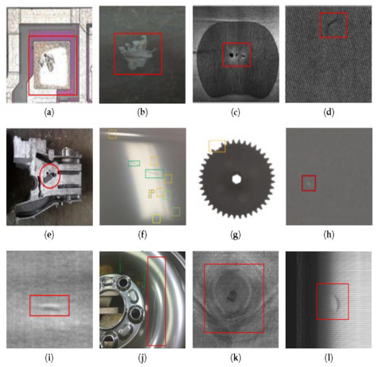
- abrasive-based machining processes
- AFM process
- molecular dynamic simulation
- artificial intelligence
- regression analysis
1. Introduction
1.1. An Overview of Abrasive-Based Machining Processes and Their Types
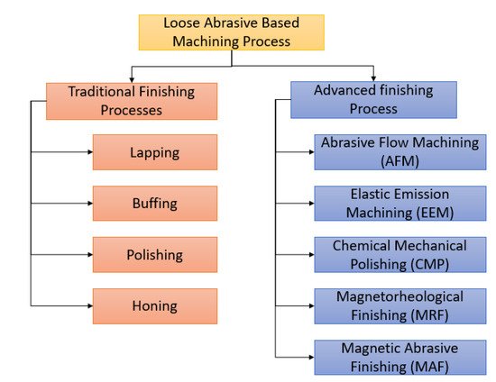
1.1.1. Loose Abrasive-Based Machining Processes
| S. No. | Loose Abrasive-Based Method | Typical Materials | Principle | Average Surface Roughness (Ra µm) | Application | Ref. | |
|---|---|---|---|---|---|---|---|
| 1. | Traditional Finishing Processes | Lapping | Metals | Harden the trapped partials between the surface of the workpiece and a soft counter formal surface | 0.05 µm to 2.5 µm | Improving the surface finish in loose abrasive-based machining | [28] |
| Buffing and Polishing | Metal and wood | Finishing the surface is performed through a wheel or an abrasive | 0.1 µm to 0.41 µm | Smoothing the material | [29] | ||
| Super abrasive machining | Titanium, nickel-based alloys and metal matrix composites, etc. | Finishing of Hard surfaces using polycrystalline diamond (PCD) or polycrystalline cubic boron nitride (PCBN) tools | 0.0127 µm–0.203 µm | Hard materials | [28] | ||
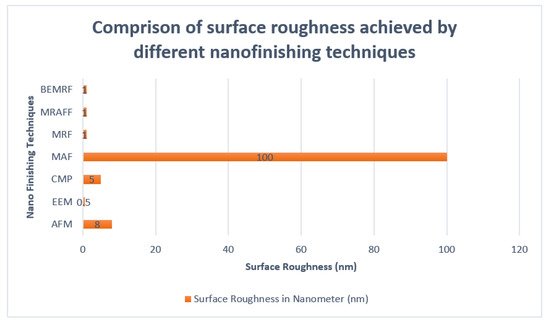
| 2 | Advanced finishing Process | Abrasive Flow Machining (AFM) | Hardened steel | Removing material from the surface of the material using sliding of abrasive particles of another material | 0.184 µm | Can deal with complex components | [26,28,30] |
| Elastic Emission Machining (EEM) | silicon | removing the material atom by atom with no cracks, deformation, or deep indentations | Less than 0.0005 µm | Removing material in loose abrasive-based machining | [28,30,31] | ||
| Chemical Mechanical Polishing (CMP) | silicon | A layer is formed between the workpiece and the slurry by chemical reaction. This layer is softer than the material of the original workpiece, which can be easily removed. | 0.005 µm to 0.01 µm | used in the finishing of the wafers made from silicon | [28,30,32] | ||
| Magnetic Abrasive Finishing (MAF) | silicon nitride | In this process, ferromagnetic particles are mixed with the particles of the workpiece. This mixture is brought close to the surface of the workpiece to be finished. | Less than 0.01 µm | Finishing the surface of nano-chips | [28,30] | ||
| Magnetorheological Finishing (MRF) | Flat BG7 glass | To finish the surface in this process, magnetorheological fluid (MR fluid) is used. This fluid consists of iron particles, carbonyl iron particles (CIPs), carrier fluid, and abrasive particles. The viscosity of this fluid is increased when it comes under the effect of the magnetic field. The CIPS arrange along the magnetic force line, and then the abrasive particles are entangled within the chains, and their motion causes the material removal |
Less than 0.001 µm | Finishing micro/Nano-chips | [28,30] | ||
| Magnetorheological Abrasive Flow Finishing (MRAFF) | This method is an extended version of MRF. the extrusion of the medium of the magnetorheological polishing is performed through the surface of the workpiece | Less than 0.001 µm | Finishing softer material than MRF | [30,33,34] | |||
| Ball end Magnetorheological Finishing (BEMRF) | Metal mirror and glass | for the finishing, this process uses the rotating spot of the stiffened MR fluid | Less than 0.001 µm | Used in the finishing of the complex 3d geometry | [35] | ||
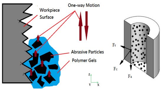
1.1.2. Abrasive Flow Machining (AFM)
1.1.3. Developments in AFM Process
-
“Elastic deformation”: it correlates with rubbing
-
“Plastic deformation (ploughing)”: it correlates with the material being displaced without being alleviated.
| S. No. | AFM Variants | Working Principles | Working Polishing Fluid (Media) | Commercial Process Names |
|---|---|---|---|---|
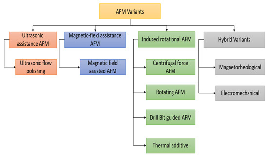
| 1. | Ultrasonic-assistance | Use of ultrasonic vibration along the AFM fixture | Viscoelastic polymer-based media | Ultrasonic float polishing (UFP) Ultrasonic-assisted AFM (UAAFM) |
| 2. | Rotational-assistance | Rotating the AFM fixture | Viscoelastic polymer-based media | Rotational AFF (R-AFF) Drill bit guided AFM (DBG-AFM) Helical AFM (HLX-AFM) |
| 3. | Magnetic-assistance | Use of permanent magnet | Magnetic abrasive-based media | Magnetic AFM (MAFM) |
| 4. | Magnetorheological assistance | Use of Electro-magnet and magnetorheological (MR) fluid | MR fluid-based media | Magnetorheological AFF AFF (MRAFF) Rotational-MRAFF (R-MRAFF) |
| 4. | Electro-chemical assistance | Use of Electrochemical machining process along with AFM process | Electrolytes and Viscoelastic polymer-based media | Electro-chemical assisted AFM(ECAFM) Electro-chemical and Centrifugal force-assisted AFM (EC2A2FM) |
| 5 | Centrifugal force assistance | Use of Centrifugal forces | Viscoelastic polymer-based media | Centrifugal force-assisted AFM (CFAAFM) Thermal Additive centrifugal AFM (TACAFM) |
| S. No. | Ref. | Typical Materials | Application | Surface Roughness (µm) |
|---|---|---|---|---|
| 1. | Guo et al., 2020 [83] | Inconel 718 | AM parts | Ra 0.1 μm was the final surface roughness value. |
| 2. | Mali et al., 2018 [84] | ABS | FDM printed parts | Change in Ra 21.37 μm for the external surface and 6.27 μm for the internal surface was found. |
| 3. | Subramanian et al., 2016 [85] | Co-Cr alloy | Bio-implant, i.e., Hip Joint | It was found that the surface roughness decreased from beginning R, value 502 nm to final R, value 39 nm. |
| 4. | Kumar et al., 2015 [86] | Ti-6Al-4V | Bio-implant, i.e., Knee Joint | The final surface roughness was measured to be 35–78 nm. |
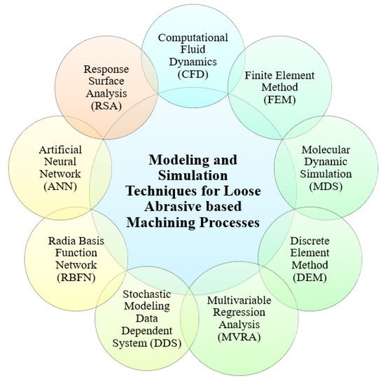
2. Mathematical Modeling and Simulation Approaches for Abrasive Machining Processes
Classification of Modeling and Simulation Techniques for Abrasive-Based Machining Processes
3. Review of Simulation Techniques for Abrasive-Based Machining Processes
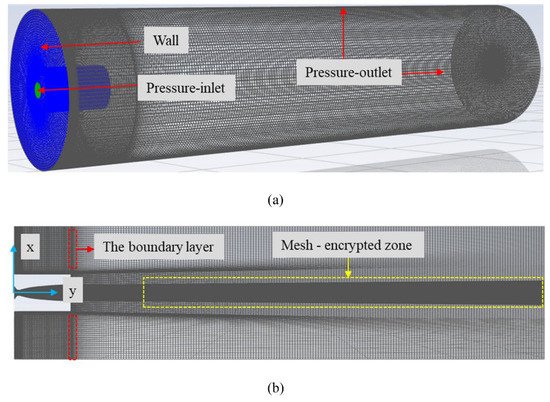
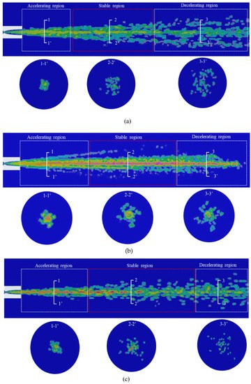
3.1. Computational Fluid Dynamics (CFD)

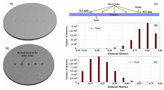
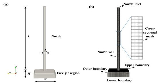
3.1.1. Pre-Processing
3.1.2. Meshing
3.1.3. Solving
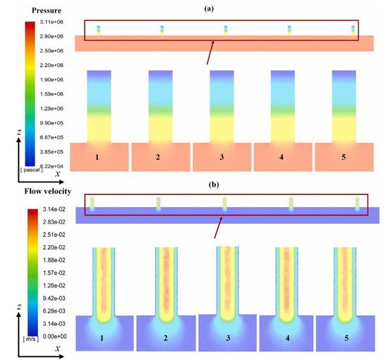
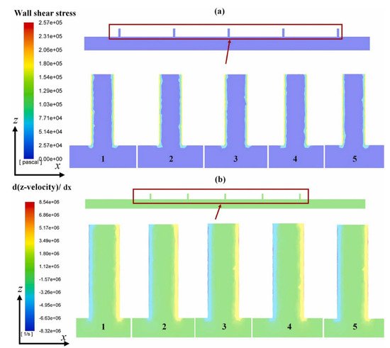
3.1.4. Post-Processing
3.1.5. Applications
| References | Work-Piece Material | Type of Abrasive-Based Process | Important Input and Output Variable Considered | Software Tool | Remarks |
|---|---|---|---|---|---|
| [94] | hard materials | Magnetic field-assisted finishing (MFAF) | Continuity and momentum | - | The active abrasive grain axial force is higher than the force of the reaction due to the strength of the material. CFD is an effective tool for predicting the surface roughness in abrasive flow-based machining. |
| [93] | Silicon carbide | Abrasive flow machining (AFM) | Shear modulus, elastic modulus, damping factor, stiffness | ANSYS CFX | CFD is an effective tool for predicting the surface roughness in abrasive flow-based machining. |
| [115] | - | Abrasive flow machining (AFM) | “Density, the extrusion pressure, piston velocity, abrasive hardness, particle hardness and media viscosity, workpiece hardness.” |
ANSYS FLUENT | The process was a precision finishing operation. Therefore, the removed material is low. This amount can be increased with the increase in the number of cycles. The modeling and the simulation are very important due to the high number of parameters |
| [121] | Visco-elastic materials | “Ultrasonic assisted abrasive flow machining (UAAFM)” | “Fluid pressure, the velocity profile of the fluid, temperature distribution in the working fluid, wall shear, angle of impact, and finishing rate” | Commercial simulation tool for CFD | The impact angle ‘θ’ plays a major role in the machining process and improves effectiveness. Wall shear helps predict if the process has better finishing rates. |
| [134] | Turbine blades | Abrasive wear | Size and shape of quartz particles, leakage flow through clearance gaps, blade life, and efficiency. | When compared with the data from the actual erosion in turbines, the CFD results give more information. The leakage flow through clearance gaps of guide vanes causes erosion in the runner blade inlet. |
This entry is adapted from the peer-reviewed paper 10.3390/met12081328