3-D surgical planning for restorative osteotomy is costly and time-consuming because surgeons need to be helped from commercial companies to get 3-D printed bones. However, practitioners can save time and keep the cost to a minimum by utilizing free software and establishing their 3-D printers locally. Surgical planning for the corrective osteotomy of antebrachial growth deformities (AGD) is challenging for several reasons (the nature of the biapical or multiapical conformational abnormalities and lack of a reference value for the specific breed). Pre-operative planning challenges include: a definite description of the position of the center of rotation of angulation (CORA) and proper positioning of the osteotomies applicable to the CORA. In the present study, we demonstrated an accurate and reproducible bone-cutting technique using patient-specific instrumentations (PSI) 3-D technology. The results of the location precision showed that, by using PSIs, the surgeons were able to accurately replicate preoperative resection planning. PSI results also indicate that PSI technology provides a smaller standard deviation than the freehand method. PSI technology performed in the distal radial angular deformity may provide good cutting accuracy. In conclusion, the PSI technology may improve bone-cutting accuracy during corrective osteotomy by providing clinically acceptable margins.
- 3-D dimension, Osteotomy, Canine
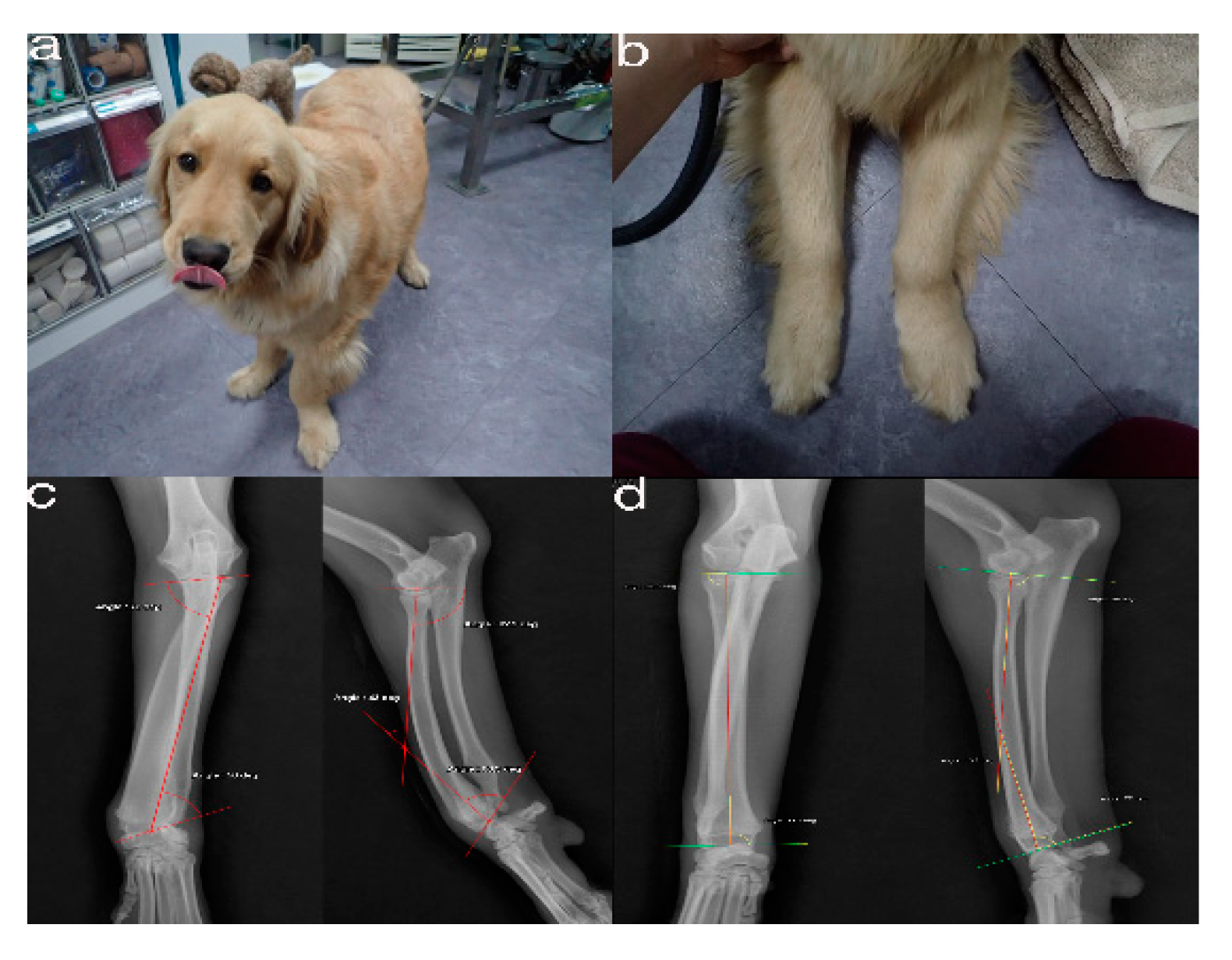
Figure 1. The images show the antebrachial growth deformity (AGD)-affected (left leg) and contralateral unaffected-antebrachium (right leg) with the joint-orientation angles (a,b), and orthogonal radiographs (c,d).
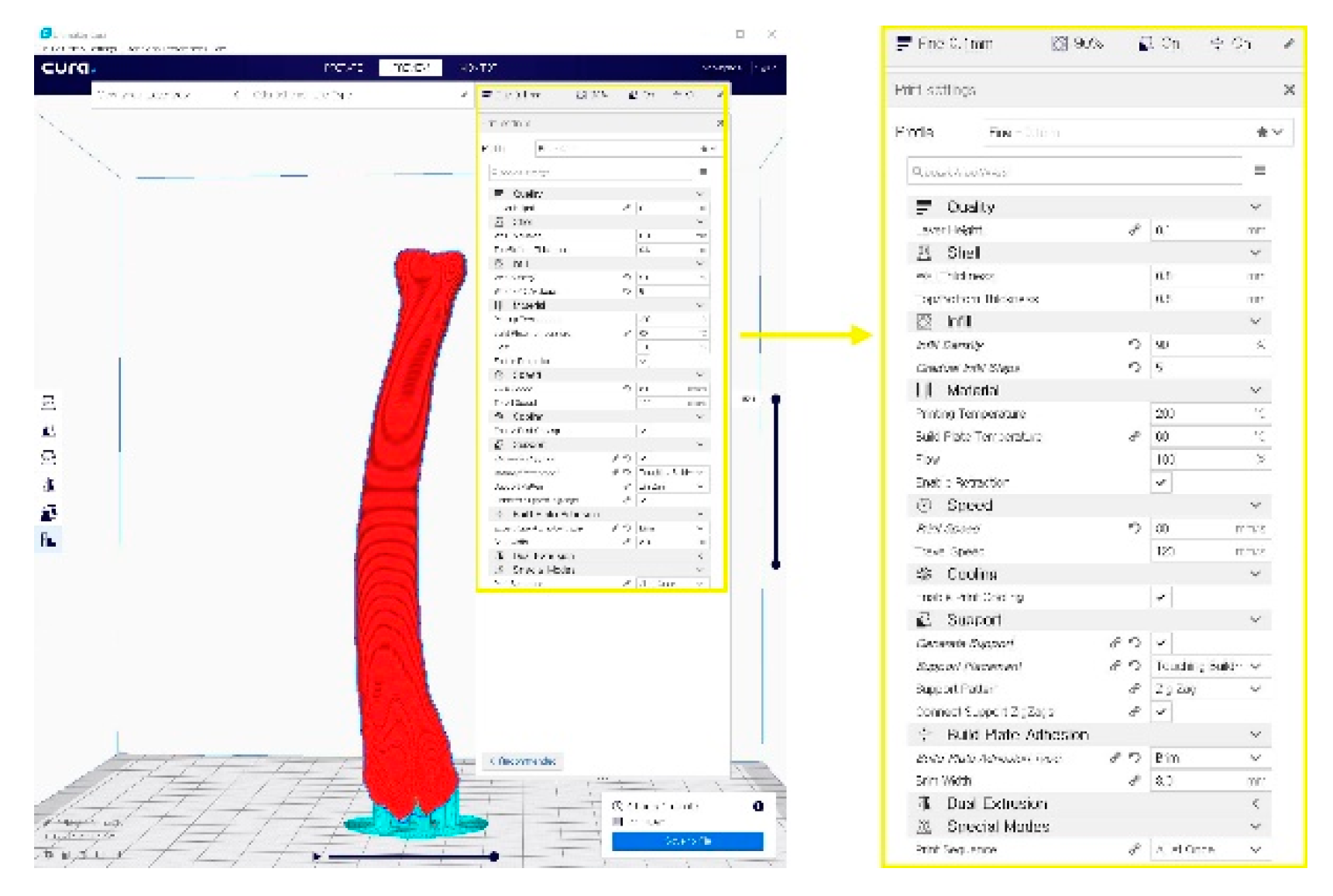
Figure 2. A G-code file generating process for the 3-D printing process. It can be generated from the STL image using the CURA application program.
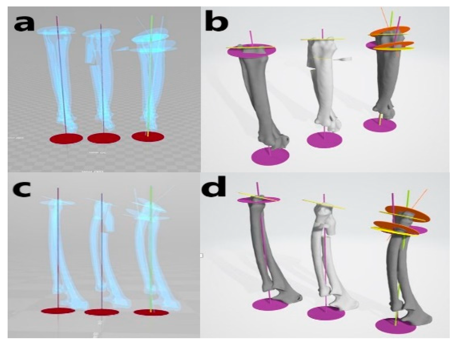
Figure 3. Virtual simulative corrective osteotomy. Surgical simulations were performed in virtual reality to predict postoperative conditions. Note the change in the axis before and after the virtual corrective osteotomy. The figure on the left (a,c) shows penetrated images and on the right (b,d) are 3-D rendering images.
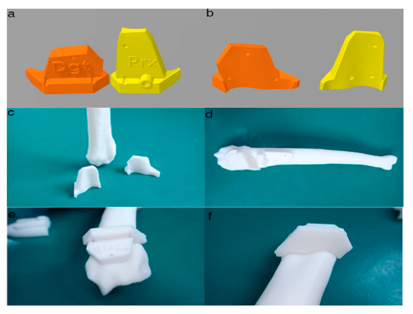
Figure 4. Final designs of patient-specific instrumentation (PSI) models were demonstrated through 3-D rendering images (a,b), 3-D printed PSIs (c), and the PSIs positioning on a rapid prototyping (RP) bone model precisely (d–f). The patient-specific cutting guides added a drill guide for the bone plate and screw placement. The PSIs attached on the RP bone model in-situ (d–f).

Figure 5. Rapid prototyping bone models were fabricated with the polylactic acid material using the fused deposition modeling method (above, a,b) and then the phantom bone models were fabricated for this study (below, c).
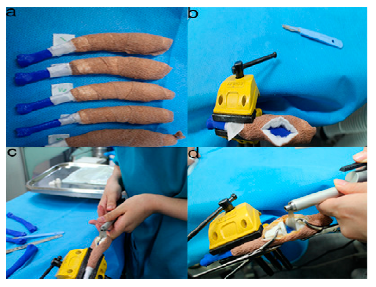
Figure 6. The position and angles for the cutting procedures. Prior to the ex-vivo osteotomy, each of the five operators were directed to position the phantom bone model to a vise (a,b). The surgical planning conditions for the freehand method were the same as the patient-specific instrumentation (PSI) method (c). Positioning PSI was ordered without positioning aids, but was only fixed on the rapid prototyping model using the bone-holding forceps or K-wires for temporary fixation (d).
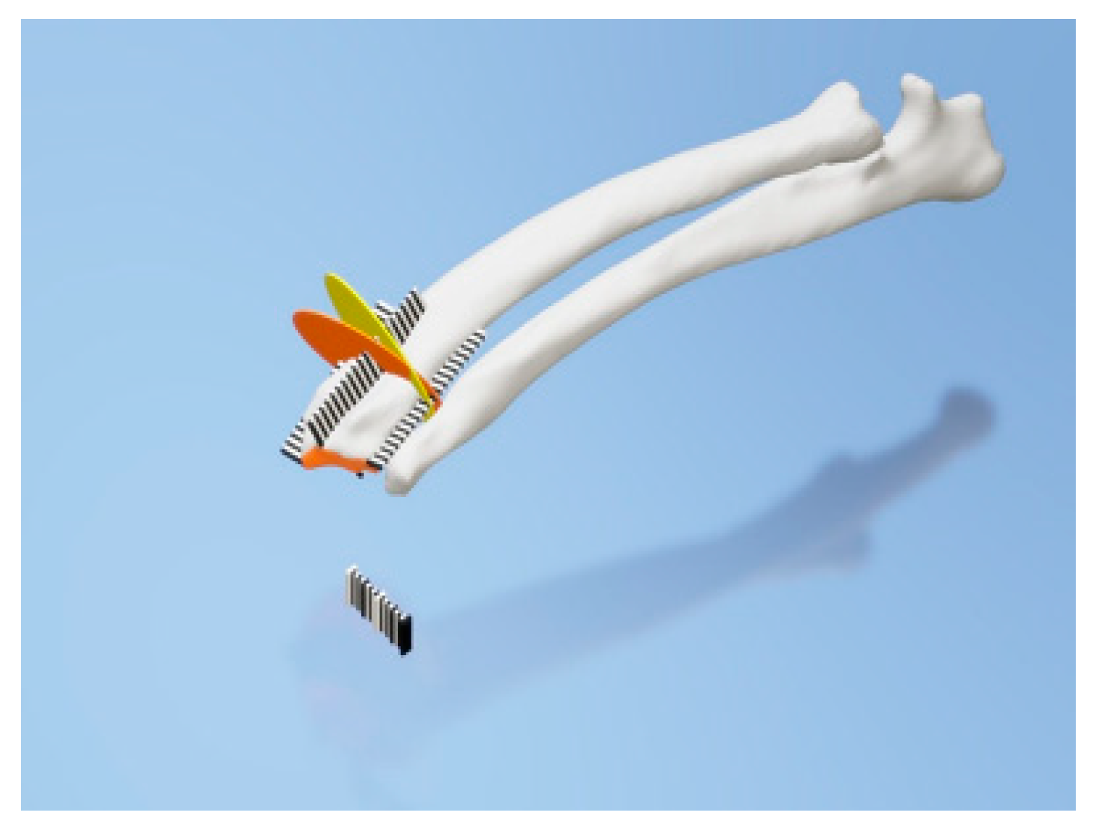
Figure 7. Rulers were attached to the cranial, caudal, medial, and lateral bone model surfaces. The orange and yellow plates show the osteotomy target plane. The black and white striped bar is made 1 mm against each space to indicate the distance from the edge of the joint surface.
This entry is adapted from the peer-reviewed paper 10.3390/ani10091445