Your browser does not fully support modern features. Please upgrade for a smoother experience.
Please note this is an old version of this entry, which may differ significantly from the current revision.
Subjects:
Energy & Fuels
The transition to the use of supercritical carbon dioxide as a working fluid for power generation units will significantly reduce the equipment′s overall dimensions while increasing fuel efficiency and environmental safety. Structural and parametric optimization of S–CO2 nuclear power plants was carried out to ensure the maximum efficiency of electricity production.
- supercritical carbon dioxide
- thermodynamic cycle
- power plant
- optimization
1. Introduction
1.1. Promising Way to Increase Efficiency and Decrease the Capital Cost of Nuclear Power Plants
Today in the Russian Federation, there are 11 nuclear power plants (NPPs) with 38 operating power units and a total installed capacity of 30.3 GW. The majority of them, 55%, are equipped with a pressurized water reactor (PWR), and the most widely used among them is the VVER–1000 type. Besides the PWRs, NPPs also operate fast breeder reactor (FBR) BN–800 with sodium heat carrier, 2100 MW heat power, 800 MW supplied power, and 39.4% net efficiency. Moreover, a new reactor facility BREST–OD–300 is under development. This FBR has a lead heat carrier, a two–circuit heat transport to the steam turbine and supercritical steam parameters. A common feature of these NPPs is the presence of the steam turbine cycle, which determines the mass and dimensions of the main energy equipment, especially of steam turbines, and rather low thermal efficiency.
A prospective method for increasing the NPP fuel efficiency and its investment reduction is an application of the supercritical carbon dioxide (S–CO2) working fluid. It allows for use of the Brayton cycle with low auxiliary power consumption, moderate initial temperature, and compact dimensions of the main energy equipment [1,2,3]. This direction has been actively developed since the middle of the past century [4,5,6,7]. This area of development arises scientists′ interests around the world largely because of carbon dioxide′s competitive advantages compared to other working fluids.
The carbon dioxide heat carrier has a low critical temperature of 30.98 °C and a pressure of 7.38 MPa (Figure 1). The low carbon dioxide critical temperature is near to the ambient atmosphere, which allows the working fluid compression near the saturation line (the CO2 density is quite high at the near–critical parameters) [8,9], reducing the compressor work and the temperature of heat removed from the cycle without the working fluid condensing. Besides, carbon dioxide is less aggressive than water and shows its corrosion activity only in the presence of moisture content in the working fluid or with a water film on a metal surface. The carbon dioxide and water working fluid prices are compatible.
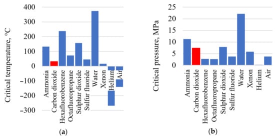
Figure 1. Thermophysical performance of the promising heat carriers: (a) heat carrier critical temperature; (b) heat carrier critical pressure.
The advantages of carbon dioxide compared to air and water in the role of the working fluid are caused by its thermophysical performance (Table 1) in conditions typical for steam and gas turbine facilities. The high density of carbon dioxide at given turbine inlet and outlet conditions leads to S–CO2 turbine mass and dimensions being smaller than those of the steam or gas turbines. The airfoil grid friction losses in an S–CO2 turbine will be smaller than those in a steam or gas turbine because of carbon dioxide′s smaller viscosity [10].
Table 1. Thermophysical properties of different working fluids at typical parameters for steam, gas, and carbon dioxide turbine facilities.
| Facility Type | Turbine Inlet/Outlet Temperature and Pressure | Turbine Inlet/Outlet Working Fluid Density, kg/m3 | Turbine Inlet/Outlet Working Fluid Kinematic Viscosity, 107 m2/s |
|---|---|---|---|
| Steam turbine power plant (H2O) | 540 °C, 23.5 MPa/29 °C, 4 kPa | 74.6/0.004 | 4.3/26.5 |
| Combined cycle power plant (air) | 1100 °C, 1.3 MPa/515 °C, 0.1 MPa | 3.3/0.44 | 162.4/840.4 |
| S–CO2 power plant (CO2) | 540 °C, 25 MPa/407 °C, 8 MPa | 155.8/70.8 | 2.4/4.5 |
1.2. A State-of-the-Art Review of the S–CO2 Brayton Cycles
Long-term thermodynamic studies of S–CO2 power facilities resulted in the development of the five cycles presented in Figure 2.
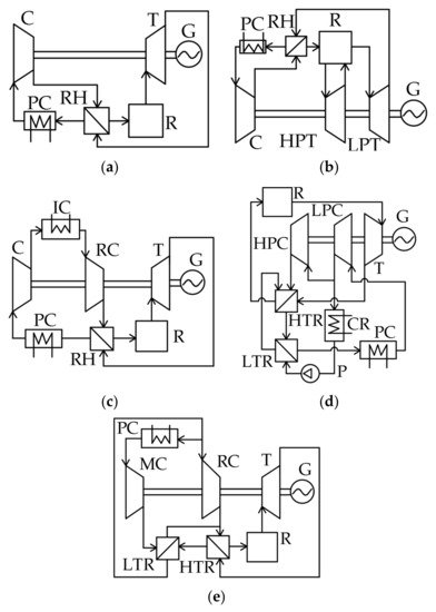
Figure 2. Supercritical CO2 Brayton cycles: (a) S–CO2 Brayton cycle with regeneration; (b) S–CO2 Brayton cycle with reheating; (c) S–CO2 Brayton cycle with intermediate cooling; (d) S–CO2 Brayton cycle with partial cooling.; (e) S–CO2 Brayton cycle with recompression.
The simplest S–CO2 cycle is a closed Brayton cycle with the heat utilization of the exhaust gases (Figure 2a). The recirculating carbon dioxide enters the compressor (C), then the compressed fluid enters the regenerator (RH). The pre-heated flow enters the reactor (R) where its temperature increases. Then, the supercritical fluid is sent to the turbine (T) that drives the electricity generator (G). After the expansion, the turbine exhaust gas enters the regenerator, where it transfers heat to the compressed working fluid. Before it enters the compressor, the cooled CO2 flow is sent to the cold source, or pre-cooler (PC), where the working fluid is additionally cooled.
The thermal efficiency is about 42% for 550 °C initial temperature, 32 °C compressor inlet temperature, and 25 MPa compressor outlet pressure. Studies of the turbine inlet pressure′s influence upon the S–CO2 Brayton cycle′s efficiency show that its increase by 2 MPa in the range of 13.8–27.6 MPa causes an efficiency increase of 0.71% [11], and a 150 °C initial temperature increase leads to a thermal efficiency increase of 5.5%.
Reheating (Figure 2b) may increase the S–CO2 Brayton cycle efficiency. This cycle differs from the previous one (Figure 2a) by the second working fluid supply to the reactor. Pressurized carbon dioxide flow is sent by the compressor to the regenerator, where it is heated by the low-pressure turbine (LPT) outlet flow. Then, the flow is sent to the reactor for its temperature increase up to the cycle initial temperature. After that, the flow is sent to the high-pressure turbine (HPT) flow path, where it expands to half of the initial pressure. Then, the flow re-enters the reactor for reheat. Afterward, the CO2 flow expands in the LPT and enters the regenerator, where it transmits heat to the compressor outlet flow. From the regenerator outlet, the hot flow is sent to the cooler, and then it re-enters the compressor.
The introduction of the working fluid reheat is followed by an increase of turbine outlet temperature, which increases the reactor inlet temperature and the mean integral temperature of heat supply to the cycle. Thermodynamic studies [7,12] reveal that the efficiency increase is maximal when the high-pressure turbine expansion ratio is equal to the low-pressure turbine one. The cycle efficiency is about 41.5% at 550 °C and 25 MPa initial cycle parameters and the turbine outlet pressure of 7.5 MPa. However, it should be noted that the introduction of an additional superheater will inevitably cause pressure losses in it. A 10% increase in pressure losses in the range of 0–250 kPa reduces the facility efficiency by 0.11%. With a further increase of the superheater pressure losses, application of the reheat will not be reasonable because it reduces the cycle efficiency. The introduction of the secondary reheat allows the supercritical CO2 Brayton cycle efficiency increase by 0.20 to 0.26% at the heater pressure losses below 125 kPa.
One more method for the efficiency increase of the simplest supercritical CO2 Brayton cycle is the introduction of intermediate cooling that reduces the compressor energy consumption (Figure 2c). In contrast to the regeneration cycle (Figure 2a), this cycle uses low- pressure compressor (LPC) and high-pressure compressor (HPC) as well as an intermediate cooler (IC). After the low-pressure compressor, the working fluid passes the cooler, where it cools and enters the high-pressure compressor, where it reaches the cycle initial parameters. The maximal increase of this cycle′s thermodynamic efficiency is reached when the second compressor pressure ratio is 1.5–1.9 times higher than the first compressor one. In this case, the S–CO2 Brayton cycle efficiency increases by 0.8%.
In addition to the above schemes, one more way toward S–CO2 Brayton cycle efficiency improvement is the use of partial cooling (Figure 2d) [6]. This cycle differs from the cycle with regeneration by the application of a high-temperature regenerator (HTR) and low-temperature regenerator (LTR), condenser (CR), pump (P), and recompressing compressor (RC). The flow pressurized in the compressor is split into two parts: the first is sent to the RC and the second is cooled in the condenser and also compressed by the pump. The second flow of compressed CO2 is heated in the LTR by the exhaust gas heat and then mixes with the first CO2 flow in the HTR. After that, the flow is supplied to the reactor, where it is heated up to the cycle′s initial temperature. The reactor exhaust supercritical CO2 enters the turbine that drives the power generator. Then, the expanded gas is directed to the sequentially connected HTR and LTR for heat utilization. Afterwards, the flow is cooled in the pre-cooler before it enters the compressor. This solution improves the regeneration system efficiency by means of the heat exchangers′ operation at different pressures. The S–CO2 Brayton cycle has 44.8% efficiency at a 550 °C cycle initial temperature and 25 MPa initial pressure.
Figure 2e shows the supercritical CO2 Brayton cycle with recompression, which is a simplified modification of the partial cooling cycle presented in Figure 2d. This cycle differs from the partial cooling cycle by the absence of a pump and condenser. The carbon dioxide flow is split into two parts upstream of the pre-cooler. The first part is cooled and supplied to the main compressor, where it reaches the initial parameters. The second part is directly supplied to the recompressing compressor, where it is also compressed up to the initial cycle pressure. After the main compressor, the compressed CO2 flow enters the LTR, where it is heated by the outlet carbon dioxide flow up to the temperature equal to the second CO2 flow temperature after the RC. Then, the two flows merge and enter the HTR, where they are also heated up to the reactor inlet temperature by heat utilization of the exhaust gases. Then, the reactor heats the working fluid up to the cycle′s initial temperature. Then, the flow enters the turbine that drives the power generator. After the flow expands in the turbine, the hot exhaust gases are cooled in the sequentially connected HTR and LTR and then split into two flows again.
This scheme solves the problem of low efficiency of the exhaust gases′ heat utilization. This problem is related to the remarkable difference of the regenerator hot and cold flows′ specific heat capacity. This difference is a specific feature of the S–CO2 Brayton cycle with regeneration. In other words, the split of compressed flow and introduction of the LTR and HTR provides deeper utilization of the exhaust gases heat and smaller heat losses in the cooler. The result of this technical solution is that the S–CO2 Brayton cycle efficiency increases up to 46%.
1.3. Summary of the Thermodynamic Investigation Results for the S–CO2 Brayton Cycles
Most of the published thermodynamic investigations are obtained at incomparable conditions, at different input data and calculation methods. As a result, one can see different evaluations of similar factors′ influence on thermal efficiency. For example, the study of the S–CO2 recompression Brayton cycle efficiency [11] shows that a 100 °C increase in the turbine inlet temperature in the 500–1000 °C range increases the efficiency by a 2.0% average, but according to the results in [6], this increase is 3.3%. On the other side, study [7] shows that a 100 °C increase of the turbine inlet temperature in the 550–850 °C range increases the mean cycle efficiency by 4%, and according to [13], in the 550–700 °C range, the same temperature increase leads to the 5% increase in efficiency.
Table 2 summarizes the main results of thermodynamic studies [6,7,11,13,14] of the S–CO2 recompression Brayton cycle. The results show a remarkable evaluation difference and determine the relevance of the comparison of carbon dioxide cycles under comparable conditions.
Table 2. An influence of parameters on the S–CO2 recompression Brayton cycle efficiency.
| Parameters | Parameter Range | Influence upon Efficiency | Reference |
|---|---|---|---|
| Compressor outlet pressure, pmax, MPa | 15–30 | 1 MPa increase ⇒ 0.2–0.8% efficiency increase | [7] |
| Turbine inlet temperature, t0, °C | 550–850 | 100 °C increase ⇒ 4% efficiency increase | [7] |
| Turbine inlet temperature, t0, °C | 500–1000 | 100 °C increase ⇒ 3.33% efficiency increase | [6] |
| Turbine inlet temperature, t0, °C | 500–1000 | 100 °C increase ⇒ 2% efficiency increase | [11] |
| Turbine inlet temperature, t0, °C | 550–700 | 100 °C increase ⇒ 5% efficiency increase | [13] |
| Turbine inlet temperature, t0, °C | 32–50 | 10 °C increase ⇒ 2,7% efficiency reduction | [7] |
| Turbine inlet pressure, p0, MPa | 10–25 | 1 MPa increase ⇒ 0.2–0.4% efficiency increase | [14] |
| Turbine efficiency, η, % | 85–95 | 5% increase ⇒ 2% efficiency increase | [13] |
| Compressor efficiency, η, % | 85–90 | 5% increase ⇒ 1% efficiency increase | [13] |
| Regenerators minimal temperature difference, Δ, °C | 5–10 | 5 °C increase ⇒ 1% efficiency reduction | [13] |
To ensure the possibility of an objective comparison of the thermodynamic efficiency of S–CO2 power cycles, a preliminary optimization of key parameters was carried out using the Aspen Plus software package. Table 3 summarizes the main thermodynamic performance of the five cycles described above. The supercritical CO2 Brayton cycle with recompression has a maximal net efficiency of 47.28% at the initial temperature and pressure of 550 °C and 35 MPa. The high working fluid temperature at the heat supply source inlet of the S–CO2 recompression Brayton cycle defines its prospects for the NPP reactor heat utilization.
Table 3. Thermodynamic optimization results for the S–CO2 Brayton cycles.
| With Regeneration | With Reheat | With Inter-Cooling | With Partial Cooling | With Recompression | |
|---|---|---|---|---|---|
| Cycle initial temperature t0, °C | 550 | 550 | 550 | 550 | 550 |
| Cycle initial pressure, p0, MPa | 35 | 35 | 45 | 25 | 35 |
| Cycle final pressure, pc MPa | 7.5 | 7.5 | 7.5 | 5 | 7.7 |
| Reheat pressure, prh, MPa | – | 10 | – | – | – |
| Heat supply to the cycle in reactor, Q0, MW | 33.03 | 33.91 | 39.12 | 28.85 | 26.43 |
| Heat loss from the cycle in coolers, Qc, MW | 19.09 | 19.09 | 22.17 | 15.84 | 13.88 |
| Turbine power Nt, MW | 19.66 | 20.54 | 22.46 | 20.28 | 18.96 |
| Compressor power, Nc, MW | 5.73 | 5.73 | 6.05 | 7.35 | 6.46 |
| High-temperature and low-temperature heat exchanger thermal power, Qreg, MW | 30.80 | 44.92 | 32.60 | 18.61/9.73 | 13.00/20.22 |
| Working fluid temperature at the source of heat inlet, treact.in, °C | 295 | 427/398 | 280 | 320 | 344 |
| Cycle net efficiency, η, % | 42.2 | 43.70 | 41.96 | 44.80 | 47.28 |
Despite numerous studies′ results on the CO2 operating NPPs, many questions are not yet answered. Specifically, the studies do not consider the nuclear reactor influence upon the outer CO2 circuit [15,16].
2. Structural and Parametric Optimization of S–CO2 Nuclear Power Plants
Change of the working fluid from water to carbon dioxide influences the energy equipment composition and performance, as well as the parameters of fluid in the thermal scheme. This approach produces changes in the facility efficiency and the installed capacity price. Finally, it influences the electricity production′s primary cost. The carbon dioxide NPP thermodynamic investigation and development makes a base for the comparison of the equipment composition, the key parameters in the thermal flow schemes, and evaluation of the power production effect caused by the working fluid change.
The cycles′ working fluid parameters are different; therefore, the power facility equipment will be also different, which influences the facility price and the power auxiliary consumption. For example, in the Brayton recompression cycle with VVER-1000, the auxiliary consumption consists of the CO2 compressor power, the cooler flow pump circulation power, the main circulation pump in the VVER-1000, and BN-800 reactors that provide the heat carrier circulation in the reactor circuits, and the compressors drive power. In the NPP with water working fluid, auxiliary consumption consists of the condensate circulation, feeding and booster pumps power, and the same main circulation pumps as in the recompression cycle of the VVER-1000 and BN-800 reactors.
Comparing the equipment composition in carbon dioxide NPP and steam turbine NPP, the following performance characteristics may be highlighted:
- -
-
Electric power production (Figure 7a);
- -
-
Grid supplied electric power (Figure 7b), which is the difference between the power production and the total auxiliary power consumption (Figure 7e);
- -
-
The main auxiliary power consumption in the NPP carbon dioxide and steam turbine external circuit, including the compressor power (Figure 7c), the power of the condenser, and cooler circulation pumps (Figure 7d);
- -
-
The cold source specific losses (Figure 7f) are the cold source losses divided by the reactor thermal power.
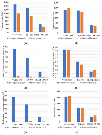
Figure 7. Technical performance comparison of recompression cycle and steam turbine unit for NPP with the different reactor types: (a) gross power; (b) net power; (c) working fluid compression power consumption; (d) circulation pumps′ power consumption; (e) total auxiliary power consumption; (f) cooler heat losses.
The turbine power output depends upon its heat drop and the working fluid mass flow. A carbon dioxide NPP available heat drop is 12 times smaller than the steam turbine one, but the carbon dioxide turbine mass flow is 12 times larger than the steam turbine one. In the carbon dioxide cycle, there is no regeneration bleeding, so the whole CO2 flow produces power in the whole turbine flowpath. Therefore, the carbon dioxide turbine power production is approximately 1.5 times larger (Figure 7a). On the other side, the main carbon dioxide power consumption is the CO2 recompression compressor drive power (Figure 7c), which is about 18% of the reactor thermal power.
A steam turbine NPP has much lower auxiliary power consumption than a carbon dioxide one. This is explained as follows. In a steam turbine NPP, the liquid working fluid pressure is raised up to the subcritical pressure, and in the carbon dioxide Brayton cycle, the gas working fluid is compressed up to the supercritical state (Figure 7c).
A comparison of the water and carbon dioxide heat carrier NPP presented in Figure 8 leads to the following conclusion. Changing a working fluid from steam to carbon dioxide in the VVER-1000 reactor does not increase the power facility efficiency. On the other hand, the BN-800 and BREST-OD-300 efficiency increases. It is worth mentioning that at the turbine inlet temperature t0 above 455 °C, it is reasonable to apply the carbon dioxide working fluid due to the higher thermal efficiency. At the initial temperature of 525 °C, the carbon dioxide NPP net efficiency is more than 2% higher than the steam turbine one.
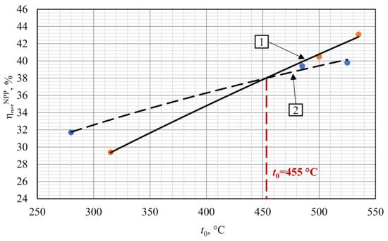
Figure 8. Influence of the working fluid type and initial temperature upon the NPP net efficiency. 1—S–CO2 NPP; 2—steam turbine NPP.
The higher S–CO2 NPP net efficiency compared to the steam turbine NPP at the initial temperature above 455 °C may be explained as follows. In the carbon dioxide power cycle, the initial temperature increase is followed by the significant increase of hot source gas inlet temperature (Table 7). (The flow temperature at the inlet of the heat exchanger transfers heat from the NPP internal circuit to the external one.) This increase is due to the carbon dioxide facility′s effective regeneration system that increases the mean integral temperature of the heat supply into the cycle, and the related cycle thermal efficiency. In turn, the initial temperature increase for the traditional steam turbine NPP equipped with BN-800 and BREST-OD-300 reactors is not followed by the feedwater temperature increase because it is limited by the upper bleeding pressure, which is relatively low in the subcritical steam turbine cycles.
Table 7. Temperature comparison at the hot source inlet for the NPP with water and carbon dioxide working fluids.
| Reactor | Working Fluid Temperature at the Hot Source Inlet, °C | |
|---|---|---|
| S–CO2 Power Cycle (CO2) | Steam Turbine Power Cycle (Feed Water) | |
| VVER-1000 | 198 | 220 |
| BN-800 | 328 | 210 |
| BREST-OD-300 | 367 | – |
Despite the efficiency increase, the conclusion on the reasonability of the change to carbon dioxide working fluid in NPP with BN-800 and BREST-OD-300 reactors may be issued only based on the technical and financial performance of the traditional and prospective facilities. Therefore, there is a need for development of the new large power carbon dioxide operating equipment and assessment of its mass and dimensions. The turbine and equipment buildup investments will be remarkably different. Thus, in further investigation, it is important to develop a scientific approach to turbine and heat exchanger equipment design for the carbon dioxide NPP.
This entry is adapted from the peer-reviewed paper 10.3390/e23081079
This entry is offline, you can click here to edit this entry!