Your browser does not fully support modern features. Please upgrade for a smoother experience.
Please note this is an old version of this entry, which may differ significantly from the current revision.
Subjects:
Engineering, Electrical & Electronic
EV charging requires either single-phase or three-phase charging stations that have unidirectionnal or bidirectional power flow capabilities. Moreover, EV charger can make use of traction powertrain equipment to achieve high power density and weight reduction in order to save space in the vehicle while increasing efficiency.
- EV charging stations
- smart charging
- power electronics
1. Specifications
Generally speaking, an electric vehicle charging station should comply with the following specifications and deliver a number of other functions, particularly durability, efficiency, and performance:
-
Implement a power factor correction: absorb a sinusoidal current free of harmonics with a power factor equal to 1.
-
Bidirectional power electronics topology that allow participating to the energy storage on the grid in order to implement a vehicle-to-grid or vehicle-to-home concept.
-
Using the traction inverter in the EV charging power electronics.
-
No additional filtering inductance by using traction motor windings.
-
Possibility of balancing battery elementary cells by implementing a part of battery management system functions.
-
Contactless power transfer.
2. Power Electronics Solutions
To meet these EV charging stations requirements, several power electronics solutions have been proposed and implemented by car manufacturers and energy providers. These solutions are briefly presented and discussed in the following subsections. The readers may refer to the following paper for more details on power electronics configurations [6].
2.1. Unidirectional Battery Charger
Unidirectional chargers have a diode bridge rectifier (DBR) associated with a filter stage and a DC/DC converter, as shown in Figure 1. The DBR can be either single-phase (Figure 1) or three-phase to increase the charging power. Moreover, a high frequency isolation transformer is used to ensure isolation during EV charging. This converter topology does not have the ability to use EV battery as energy resource and then inject power to the utility grid. However, it allows providing ancillary services, mainly voltage regulation, by supplying or absorbing reactive power from the main grid without EV battery discharging.
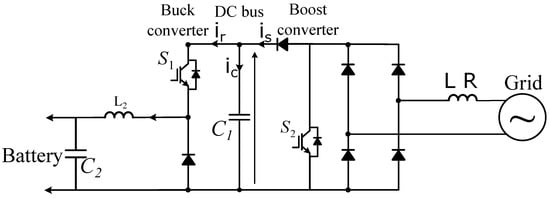
Figure 1. Unidirectional battery charger for EVs.
Unidirectional battery chargers offer a simple and easy-to-control solution to manage EV fleet and meet the requirements for safe, reliable, and cost-competitive EV charging solution. However, with the increasing penetration of EV in the transportation sector, it is intended to play a key role in the main grid regulation (mainly, frequency and voltage regulation), which can not be totally ensured using unidirectional EV chargers. Consequently, there is a need for bidirectional power flow topologies that allow EVs to act as a distributed energy storage on the power system [127,128].
2.2. Bidirectional Battery Charger
Bidirectional EV chargers are composed of two stages, which are a single-phase or three-phase active front end (AFE) followed with a bidirectional DC/DC converter, as depicted in Figure 2. AFE is a bidirectional AC/DC converter that allow regulating the DC bus voltage and controlling quasi-sinusoidal grid currents, while ensuring a unity power factor (current phase angle control) or exchanging reactive power with the power grid. The second stage allows controlling the charging current of the battery. The DC/DC converter can be either isolated or non-isolated circuit configurations as discussed in [6]. This converters topology offers a bidirectional power exchange with the main grid to support the grid during congestion periods and behave as additional energy storage during off-peak periods.
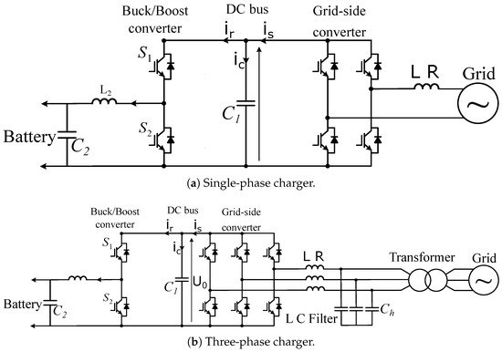
Figure 2. Bidirectional battery charger for EVs.
Bidirectional charging has several advantages compared to unidirectional charging. During EV charging operation, it has been shown that the use of bidirectional charging can increase the benefits by at least 25% compared to standard unidirectional charging through the vehicle-to-grid (V2G) principle. In bidirectional charging, the use of the battery capacity of EVs can also contribute to ancillary services, such as maintaining frequency and voltage at the nominal levels and controlling congestion risks. Indeed, this distributed energy system allows can provide/absorb active power to maintain nominal grid frequency (global parameter) and supply/absorb reactive power to regulate voltage level (local parameter).
2.3. Integrated On-Board EV Charger
AC charging typically needs an on-board AC/DC power converter. Quite interestingly, the motor and the motor drive inverter, which converts the DC power from the battery into AC power for the motor, can also be used as the on-board charger for the battery [129]. Indeed, the existing devices of the drivetrain are reconfigured with minimum additional components to allow recharging. This eliminates the need for a separate AC/DC power converter for the on-board charger. Since the drivetrain power converter is usually high power (greater than 100 kW), this also means that the EV can reach quite high charging rates (greater than 22 kW). The challenge is to design the motor drive and its control to provide the dual functionality of EV charging when stationary and EV propulsion when in motion [130,131].
Integrated on-board EV charger is a bidirectional EV charger that uses a single inverter/rectifier for all operation modes of EV. This topology allows minimizing the number of power electronic devices since the same power switches are used both for EV traction/propulsion, braking, and battery recharging. This way the cost, size, and weight of EV charger are considerably reduced. A topology of such power conversion system is provided in Figure 3 in which the same converter is used for supplying the motor and recharging EV battery. In Figure 4, the on-board charger configuration uses the traction inverter as well as the motor windings. The motor windings of each phase are split into two equivalent parts and then reconnected in reverse to cancel the torque in battery charge mode. Motor winding acts as an inductor filter so that the line currents are smooth sinusoidal currents with low THD [132]. An excellent example of this implementation is the Renault ZOE EV, which provides 43 kW on-board AC fast fast charging. The Renault has claimed to use a junction box that helps in modifying the operation of the motor and motor drive components to be used as an on-board EV charger.
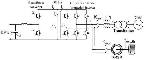
Figure 3. Bidirectional battery charger for EVs using traction inverter.
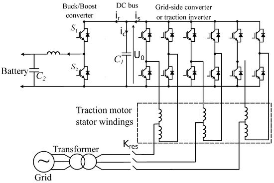
Figure 4. Bidirectional battery charger for EVs using traction inverter and motor windings.
The main issue with these integrated on-board EV chargers is the produced motor torque due to the current flowing in the motor windings. One solution to control the torque is to use a mechanical brake during battery charging. Other solutions that depend on the motor type can be mentioned: In the case of AC motor with wound rotor, cutting off the excitation cancels the magnetic field of the rotor. Therefore, the interaction between the stator and rotor magnetic fields is canceled and the zero torque condition is maintained during charging. However, even if the excitation is switched off, reluctant torque may occur, causing the machine to vibrate or even rotate. In the case of a permanent magnet synchronous motor, since it has no starting torque, the stator windings of the three-phase machine can be connected to the grid without the risk of rotor rotation. However, vibrations may still occur. Moreover, the integrated on-board EV chargers present other drawbacks as follows:
-
Need for a specially designed electrical machine;
-
Difficulty in accessing the neutral point of motor windings;
-
Reduced reliability due to the use of mechanical contactors.
2.4. Bidirectional Battery Charger Using Modular Multilevel Converters
This type of embedded chargers use modular multilevel converters (MMC), which are more attractive than two-level converters and neutral point clamp converters. MMC is an advanced voltage source converter that has competitive advantages such as output power high quality, high modularity, simple scalability, fault tolerant capability, and low voltage and current rating demand for the power switches [133,134]. In recent years, the incorporation of wideband gap semiconductors (SiC and Gan) are investigated to implement the MMC application with further advantages of high-voltage and high-power operations, low power losses, high efficiency, improved reliability, and reduced module size and cooling system [135,136].
Multilevel cascaded H-bridge converter is the best suited for battery charging applications [137,138]. Converter topology using an MMC at battery cells level to achieve both the traction inverter and on-board battery charger is shown in Figure 5. In motor mode, power flows from the batteries to the motor through the cascaded inverters. Cascaded inverters can also be used as rectifiers in battery charging mode [139,140]. It is possible to use the motor windings as an inductor, but it is more appropriate to use small external inductors.
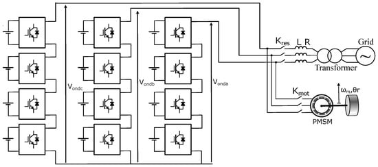
Figure 5. Bidirectional battery charger using multilevel modular converters.
2.5. Contactless Power Transfer-Based EV Charger
Inductive charging is the best alternative to conductive chargers due to the many advantages that this technology offers. In fact, this charging mode has the following advantages: accessibility, standardized charging, ease of exchanging of information with the vehicle [141], and safety for the user since there is no electrical contact and the heavy cables are eliminated. This can considerably reduce the weight of the vehicle and, thus, its energy consumption. Inductive charging is based on wireless power transfer principle [142,143], as depicted in Figure 6. In this configuration, the grid AC voltage is rectified using an AC/DC converter with a power factor correction (PFC) to ensure unity power factor and to adjust the rectified output voltage (which is usually around 400 V). A high frequency inverter is fed by the DC output voltage, producing a square voltage wave at a frequency of 85 kHz [144]. The high-frequency inverter is followed by an impedance matching network (IMN) eliminating the current harmonics produced and compensating for the reactive power due to the leakage inductance of the transmitting coil, this block is also known in the literature as the primary compensation stage. When the transmitter coil is fed with the filtered output voltage of the inverter, it produces a time-varying magnetic field that can be directed towards the receiver coil using ferrite cores allowing wireless power transfer from the ground assembly to the vehicle assembly. The time-varying magnetic field induces an AC voltage in the receiver coil at the same frequency as primary coil voltage. This voltage is applied to a secondary compensation stage (IMN) and then rectified. The rectifier can be a controlled rectifier or diode-based rectifier [145,146]. In bidirectional systems, a controlled rectifier is required to ensure a bidirectional power flow to implement the V2G concept [147,148,149]. Finally, a buck-boost DC/DC converter is used to control the current delivered to the battery.
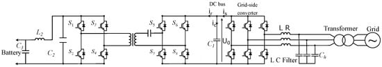
Figure 6. Contactless power transfer for EV charging.
3. Summary on EV Charging Stations Technical Requirements
EV charging modes varies according to several criteria related to efficiency, durability, performance, and cost. Several power electronics architectures have been investigated in academia and implemented in industry. With the evolution of the vehicle electrical system and the increase in charging power demand for different levels, new types of AC chargers whose operation is based on the use of traction inverter and EV motor windings are emerging. These types of chargers allow to provide high power and have a compact architecture and low cost. Moreover, inductive charging seems to be a very attractive technology for EV charging stations in the near future, especially for domestic applications.
This entry is adapted from the peer-reviewed paper 10.3390/en15166037
This entry is offline, you can click here to edit this entry!