Your browser does not fully support modern features. Please upgrade for a smoother experience.
Please note this is an old version of this entry, which may differ significantly from the current revision.
Dual phase steels (DP) are one of the most studied steels in the automotive industry, especially after the 1990s when it was decided to reduce the cars’ weight to reduce volatile organic compounds (VOC) and other emissions. The assessment regarding welding DP steel parts should be able to prevent defects from occurring, using finite element method (FEM) analysis to study the material behavior considering the parameterization used during the welding process. It is also necessary to control the possible occurrence of defects during the process, such as porosities, cracks, lack of penetration, etc., controlling the parameters of the welding fixture and ensuring that the operator follows procedures and standards. A batch sample should be subjected to some tests after production to check if there are any defects, such as dimensional errors or porosities in the bead.
- welding
- laser welding
- DP steels
- welding quality
- welding procedures
- welding defects
1. Quality Assessment Pre-Welding: Virtual Prototype Finite Element Method (FEM) Analysis
Due to advances in technology, it is now possible to prevent certain defects from occurring before starting the welding process. Indeed, there are defects that are possible to predict their behavior through numerical simulations, such as distortions and misalignment, as these defects are directly linked to the use of jigs and clamp placement (Table 1).
Table 1. How to prevent laser welding defects—pre-welding [1].
| Problem | Potential Effects |
Causes | Solutions | How to Prevent/ Control |
|---|---|---|---|---|
| Distortion and molten pool geometry |
Geometric deformations |
Welder inexperience |
Welding resorting to jigs. Study and adjust jigs through simulation. | FEM analysis |
| High heat input and number of beads. | Adjust welding parameters to reduce heat input and select the ideal quantity of beads. | |||
| Incorrect welding sequence | Study different welding sequencings through simulation. | |||
| Slow welding speed | Study different welding speeds in simulation. |
1.1. FEM Analysis
Simulation is a set of mathematical models or statistical tools, able to predict the behavior of a product when making specific inputs. Simulations can offer researchers the ability to impose certain conditions and obtain predictions about the results, which can be compared with experimental data. To exercise this comparison, it is necessary to choose an error percentage. There are several packages of software that can be used in this field, such as CAEplex, MATLAB, Ansys, OpenFOAM, EMS, SolidWorks Simulation Premium, COMSOL Multiphysics, Flow-3D, and ProModel Optimization Suite [2], among others.
To design a certain product, simulation plays a crucial role when it comes to execute a virtual prototype. This type of prototype will help to verify the ideal conditions under which the product must be manufactured. Regarding laser welding, it is possible to check the welding parameters and conditions, such as power, speed, weld bead size, operations sequencing, etc. Thus, the simulation allows the production of the product virtually to find possible unconformities before the prototype is physically executed, thereby eliminating costs of non-quality parts.
To perform a laser welding simulation of a Dual phase steels (DP) steel regarding the study of strains and distortions that might occur during welding, it is necessary to implement thermo-mechanical simulation [3][4][5]. This type of simulation is highly used for studying large-sized structures, verifying if the residual stresses and distortions are contained within the tolerances. To perform this simulation requires three stages: thermal modelling, metallurgical modelling and mechanical modelling [6].
1.1.1. Thermal Model
For large structures, it is not yet possible to complete a full simulation (due to the amount of time required), thus, several assumptions are usually made about the interaction of the material with the process, which must be reduced to the volume of the heat source itself. This assumption generates difficulties, since gas and liquid flows are neglected. Therefore, it is necessary to include these effects in the volume of the heat source [6].
Heat transfer is an important phenomenon in the simulation, since the major consequences of the laser–material interaction are obtained by its thermal expansion [6]. To calculate this volume heat source, it is necessary to solve the equation for heat transfer from the volumetric heat source to the metal during welding phase, considering convection and radiation heat losses [7]. Thus, some models can be chosen for simulating the heat source, such as Gaussian (conical heat source) and Goldak’s model. [7].
1.1.2. Mechanical Model
In this field, two mechanical models can be used: the elastoplastic (EP) model and the elastoplastic with transformation induced volumetric strain model (VEP). The simulation of these two models can be carried out under the same conditions and meshing to verify different residual stress outputs. The resolution of the mechanical equation is based on the equation of static equilibrium, solving the global deformation during welding [8].
1.1.3. Metallurgical Model
During heating, the only transformation that occurs is into austenite, which does not depend completely on the heating rate [9]. Owing to changes in thermal expansion coefficient during the welding process, the phase transformation is a key step in modeling residual stresses [10]. This stage has two phases: thermal and mechanical. To carry out this simulation, it is necessary to consider variables, such as cooling rate, laser power and speed.
2. Quality Assessment during Welding
During the laser welding process, energy can be emitted in many ways, and to be able to study this energy and the effects that it will produce in the material, various methods can be used. Several use optical or acoustic sensors to be able to have a physical model of the phenomena, which occurs between laser and material, including defects that may happen during the laser welding process (Figure 1) [11].
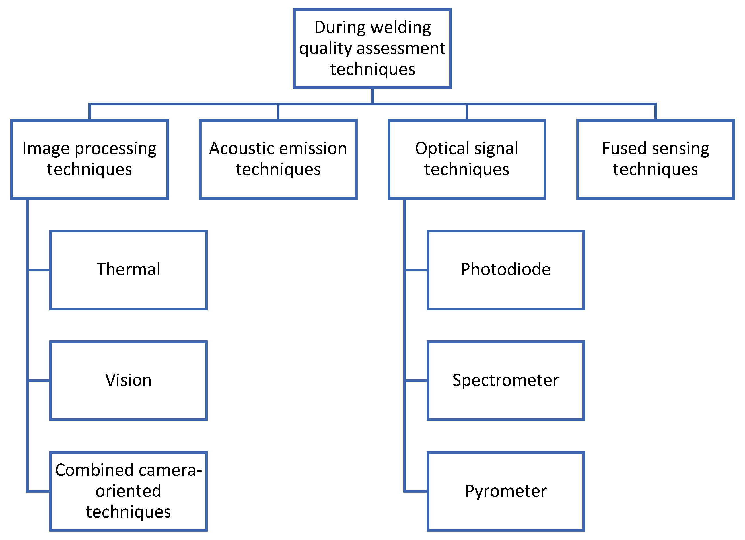
Figure 1. Quality assessment during welding [12].
In the literature, [12] shows that nowadays it is possible to control laser welding in real time and evaluate defects that might occur during the welding process, such as blowouts, undercuts and lack of penetration (Table 2).
Table 2. How to prevent laser welding defects—during welding [1].
| Problem | Potential Effects | Cause | Solution | How to Prevent/Control |
|---|---|---|---|---|
| Blowout | The bead section can be weakened, affecting the mechanical strength of the joint. | Human failure | Hire highly skilled welders with certification. | Thermal |
| Low welding current | Increase welding current | |||
| High speed | Lower welding speed | |||
| Lack of penetration | Weakening of the bead section, stress concentrations, nucleation of cracks, which can lead to joint collapse. | Low pre-heating | Increase pre-heating temperature | Thermal Combined Acoustic emission techniques Photodiode sensor Pyrometer sensor |
| High welding speed | Decrease welding speed | |||
| Human failure | Hire highly skilled welders with certification. | |||
| Undercut | Reduction in the part’s resistance when it is in working cycle. | High heat input in the joint. | Decrease welding power and adjust welding speed. | Thermal Vision Combined Photodiode sensor Fused techniques |
| Porosity | Decrease in resistance of the welding bead | Human failure | Hire highly skilled welders with certification. | Thermal |
| Excessive flow rate in the shielding gas | Control shielding gas flow | |||
| Inclusion of oxygen due to ineffective gas protection | Remove impurities and follow standards for joint preparation. | |||
| High welding speed. | Decrease welding speed. |
In the column “How to prevent/control”, several techniques have been presented, which are explained in the next section:
2.1. Image Processing Techniques
These techniques focus on extracting information, patterns and features from a set of images. They are used in various types of welding, including laser welding. They are divided into three categories:
-
Vision: with this method it is possible to characterize plasma plume, spatters and molten pool in welding. In the literature, there are papers in which a vision system was used together with vision sensor, based on the principle of triangulation in which it is possible to obtain information through 3D profiles. Some authors also used couple charged device (CCD) sensors to extract surface information, such as depth pool [17][18][19].
2.2. Acoustic Emission Techniques
With this technique, it is only possible to study the plume vapor and the workpiece. The only defect that can be verified is penetration, but since this system is very dependent on sound waves, it has the disadvantage that it is very sensitive to sound [23][24][25].
2.3. Optical Techniques
These techniques are used essentially for monitoring the welding process itself. The optical sensors are classified in the following three categories:
2.4. Fused Techniques
Fused techniques are a new belief that a multi-sensor approach can be more accurate in obtaining data from welding processes, which will improve the study of welding defects. Authors have studied combinations of infrared and ultraviolet sensors with acoustic techniques and visual sensing with photodiode sensing [34][35][36].
3. Quality Assessment Post-Welding
Even with all existing standards, there is always room for error (Figure 2). Therefore, after the laser welding process, a sample of parts should be taken and submitted to tests to verify if the batch complies to the requirements.
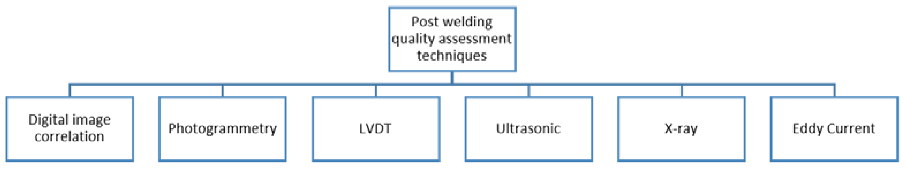
Figure 2. Quality assessment post-welding [12].
Each technique presented in Figure 2 is explained in the following section.
3.1. Digital Image Correlation (DIC)
The digital image correlation (DIC) concept used by [37][38][39] is a method of optical analysis, without contact and of total field. With the use of two cameras and image recording techniques, using correlation algorithms, the surfaces and the outline of an object can be determined using the DIC method. The surface profiles obtained before and after welding are compared with the results of the 3D deformation of the object. This method requires the proper calibration of the cameras and can be used to measure any type of transient welding distortion, as well as welding distortion after the process. The DIC software, ARAMIS®, developed by GOM©, is one of the best known in this field.
3.2. Photogrammetry
This is a method based on remote sensors that uses photographs to get the exact place of a point or surface using the triangulation of several points. To measure the distortion occurred in the welding process, the most used type is short-range photogrammetry. In this method, the camera is close to the object. The configuration used in photogrammetry is like that of DIC and can be used to obtain the 3D models of the photographed object [40].
3.3. Linear Variable Differential Transformer (LVDT)
Another method that can be used is LVDT, which is a device like an electrical transformer that measures linear displacements, measuring the variation of the induced internal voltage. The LVDT can be used to measure the size of the distortion at fixed points during welding and after cooling it [41][42].
3.4. Ultrasonic
Ultrasonic inspection methods involve the generation of ultrasonic waves that interact with the weld. If there are defects in the bead, these will cause waves to be reflected and diffracted. Within the ultrasonic waves, a technique called time of flight measurement (ToF) allows calculating the quality of the bead through its geometry. However, to apply this method, an exact knowledge of the speed of sound is necessary to define the geometry [43][44][45].
3.5. X-ray Radiography
X-rays and gamma rays can be used to show discontinuities and inclusions within opaque material. This feature has become useful in the study of weld beads, where it is possible to verify defects, such as porosities. However, this technique requires the operator to be qualified in interpreting the results. Moreover, it is very expensive due to the handling of parts, equipment and the necessary protection. Usually, it is not used in automated environments [46][47][48][49][50].
3.6. Eddy Current
Defects and changes in material properties result in changes in the signals of these currents. This method has a great ability to detect distinctive defects in welds with a depth of less than 2 mm, and it can be automated in the inspection after the welding process. Despite the advantages, it is only applicable to conductive materials. However, the surface of the welds must be accessible to the probe because the surface finish and its irregularities can interfere with the reference standard [51][52][53][54].
3.7. Magneto-Optical Detection Method
This procedure is a non-destructive testing based on magneto-optical (MO) imaging, which transforms the magnetic leakage field into a light intensity map to visualize defects [55][56][57]. In the study [58], a vertical combined magnetic field (VCNF) and a parallel combined magnetic field (PCMF) were compared to traditional magnetic fields where it was found that magneto-optical imaging under VCMF could detect weld defects of any shape and distribution accurately. This technique was also used in [59], where weld surface and subsurface cracks were detected by an MO sensor. It was shown that the magnetic flux leakage signals of the weld surface and subsurface cracks could be easily distinguished.
This entry is adapted from the peer-reviewed paper 10.3390/met12081253
References
- Silva, F.J.G. Tecnologia da Soldadura Uma Abordagem Técnico-Didática, 2nd ed.; Quântica Editora: Porto, Portugal, 2016; ISBN 9789897231704. (In Portuguese)
- Butt, J. A Strategic Roadmap for the Manufacturing Industry to Implement Industry 4.0. Designs 2020, 4, 11.
- Martinson, P.; Daneshpour, S.; Koçak, M.; Riekehr, S.; Staron, P. Residual stress analysis of laser spot welding of steel sheets. Mater. Des. 2009, 30, 3351–3359.
- Zain-ul-Abdein, M.; Nelias, D.; Jullien, J.F.; Deloison, D. Prediction of laser beam welding-induced distortions and residual stresses by numerical simulation for aeronautic application. Mater. Process. Technol. 2009, 209, 2907–2917.
- Zain-Ul-Abdein, M.; Nélias, D.; Jullien, J.-F.; Boitout, F.; Dischert, L.; Noe, X. Finite element analysis of metallurgical phase transformations in AA 6056-T4 and their effects upon the residual stress and distortion states of a laser welded T-joint. Int. J. Press. Vessel. Pip. 2011, 88, 45–56.
- Dal, M.; Fabbro, R. An overview of the state of art in laser welding simulation. Opt. Laser Technol. 2016, 78, 2–14.
- Kouadri-Henni, A.; Seang, C.; Malard, B.; Klosek, V. Residual stresses induced by laser welding process in the case of a dual-phase steel DP600: Simulation and experimental approaches. Mater. Des. 2017, 123, 89–102.
- Bonollo, P.F.H.P.A.T.F. The influence of phase transformations on residual stresses induced by the welding process—3d and 2d numerical models. Model. Simul. Mater. Sci. Eng. 2006, 14, 117–136.
- Leblond, J.; Devaux, J. A new kinetic model for anisothermal metallurgical transformations in steels including effect of austenite grain size. Acta Met. 1984, 32, 137–146.
- Deng, D. FEM prediction of welding residual stress and distortion in carbon steel considering phase transformation effects. Mater. Des. 2009, 30, 359–366.
- Shao, J.; Yan, Y. Review of techniques for on-line monitoring and inspection of laser welding. J. Phys. Conf. Ser. 2005, 15, 101–107.
- Stavridis, J.; Papacharalampopoulos, A.; Stavropoulos, P. Quality assessment in laser welding: A critical review. Int. J. Adv. Manuf. Technol. 2017, 94, 1825–1847.
- Chen, Z.; Gao, X. Detection of weld pool width using infrared imaging during high-power fiber laser welding of type 304 austenitic stainless steel. Int. J. Adv. Manuf. Technol. 2014, 74, 1247–1254.
- Speka, M.; Matteï, S.; Pilloz, M.; Ilie, M. The infrared thermography control of the laser welding of amorphous polymers. NDT E Int. 2008, 41, 178–183.
- Bardin, F.; Morgan, S.; Williams, S.; McBride, R.; Moore, A.J.; Jones, J.D.C.; Hand, D.P. Process control of laser conduction welding by thermal imaging measurement with a color camera. Appl. Opt. 2005, 44, 6841–6848.
- Hutter, F.X.; Brosch, D.; Graf, H.-G.; Klingler, W.; Strobel, M.; Burghartz, J.N. A 0.25 µm logarithmic cmos imager for emissivity-compensated thermography. In Proceedings of the 2009 IEEE International Solid-State Circuits Conference-Digest of Technical Papers, San Francisco, CA, USA, 8–12 February 2009; pp. 354–355.
- Saeed, G.; Zhang, Y.M. Weld pool surface depth measurement using a calibrated camera and structured light. Meas. Sci. Technol. 2007, 18, 2570–2578.
- Huang, W.; Kovacevic, R. A Laser-Based Vision System for Weld Quality Inspection. Sensors 2011, 11, 506–521.
- Zhang, Y.; Gao, X. Analysis of characteristics of molten pool using cast shadow during high-power disk laser welding. Int. J. Adv. Manuf. Technol. 2013, 70, 1979–1988.
- Al-Habaibeh, A.; Shi, F.; Brown, N.; Kerr, D.; Jackson, M.; Parkin, R.M. A novel approach for quality control system using sensor fusion of infrared and visual image processing for laser sealing of food containers. Meas. Sci. Technol. 2004, 15, 1995–2000.
- Von Witzendorff, P.; Kaierle, S.; Suttmann, O.; Overmeyer, L. Using pulse shaping to control temporal strain development and solidification cracking in pulsed laser welding of 6082 aluminum alloys. J. Mater. Process. Technol. 2015, 225, 162–169.
- Voelkel, D.D.; Mazumder, J. Visualization of a laser melt pool. Appl. Opt. 1990, 29, 1718–1720.
- Dorsch, F.; Braun, H.; Keßler, S.; Magg, W.; Pfitzner, D.; Plaßwich, S. Process Sensor Systems for Laser Beam Welding: Enabling and assuring reliable production. Laser Tech. J. 2012, 9, 24–28.
- Li, L. A comparative study of ultrasound emission characteristics in laser processing. Appl. Surf. Sci. 2001, 186, 604–610.
- Purtonen, T.; Kalliosaari, A.; Salminen, A. Monitoring and Adaptive Control of Laser Processes. Phys. Procedia 2014, 56, 1218–1231.
- Park, Y.W.; Park, H.; Rhee, S.; Kang, M. Real time estimation of CO2 laser weld quality for automotive industry. Opt. Laser Technol. 2002, 34, 135–142.
- You, D.; Gao, X.; Katayama, S. Multiple-optics sensing of high-brightness disk laser welding process. NDT E Int. 2013, 60, 32–39.
- Zhang, X.; Chen, W.; Ashida, E.; Matsuda, F. Relationship between weld quality and optical emissions in underwater Nd: YAG laser welding. Opt. Lasers Eng. 2004, 41, 717–730.
- Rizzi, D.; Sibillano, T.; Calabrese, P.P.; Ancona, A.; Lugarà, P.M. Spectroscopic, energetic and metallographic investigations of the laser lap welding of AISI 304 using the response surface methodology. Opt. Lasers Eng. 2011, 49, 892–898.
- Sebestova, H.; Chmelickova, H.; Nozka, L.; Moudry, J. Non-destructive Real Time Monitoring of the Laser Welding Process. J. Mater. Eng. Perform. 2012, 21, 764–769.
- Sibillano, T.; Rizzi, D.; Mezzapesa, F.P.; Lugarà, P.M.; Konuk, A.R.; Aarts, R.; Veld, B.H.I.; Ancona, A. Closed Loop Control of Penetration Depth during CO2 Laser Lap Welding Processes. Sensors 2012, 12, 11077–11090.
- Smurov, I. Pyrometry applications in laser machining. Laser-Assist. Microtechnol. 2001, 4157, 55–67.
- Bertrand, P.; Smurov, I.; Grevey, D. Application of near infrared pyrometry for continuous Nd:YAG laser welding of stainless steel. Appl. Surf. Sci. 2000, 168, 182–185.
- Farson, D.; Ali, A.; Sang, Y. Relationship of optical and acoustic emissions to laser weld penetration. Weld. J. 1998, 77, 142-s.
- Kamimuki, K.; Inoue, T.; Yasuda, K.; Muro, M.; Nakabayashi, T.; Matsunawa, A. Behaviour of monitoring signals during detection of welding defects in YAG laser welding. Study of monitoring technology for YAG laser welding (Report 2). Weld. Int. 2003, 17, 203–210.
- Smurov, I. Laser process optical sensing and control. In Proceedings of the IV International WLT-Conference on Lasers in Manufacturing, Munich, Germany, 18–22 June 2007; pp. 537–546.
- Chu, T.C.; Ranson, W.F.; Sutton, M.A. Applications of digital-image-correlation techniques to experimental mechanics. Exp. Mech. 1985, 25, 232–244.
- Chao, Y.J.; Luo, P.-F.; Sutton, M.A. Application of stereo vision to three-dimensional deformation analyses in fracture experiments. Opt. Eng. 1994, 33, 981–990.
- Peters, W.H.; Ranson, W.F. Digital Imaging Techniques in Experimental Stress Analysis. Opt. Eng. 1982, 21, 213427.
- Lightfoot, M. The measurement of welding distortion in shipbuilding using close range photogrammetry. In Proceedings of the Remote Sensing and Photogrammetry Society, Newcastle upon Tyne, UK, 11–14 September 2007.
- Dye, D.; Hunziker, O.; Roberts, S.M.; Reed, R.C. Modeling of the mechanical effects induced by the tungsten inert-gas welding of the IN718 superalloy. Met. Mater. Trans. A 2001, 32, 1713–1725.
- Masubuchi, K. CHAPTER 3-Fundamental Information on Residual Stresses Analysis of Welded Structures; Pergamon: Oxford, UK, 1980.
- Salzburger, H.J.; Mohrbacher, H.; Kralj, S.; Kozuh, Z. In-line quality control of laser welds of tailored blanks by couplant free ultrasonic inspection. In Proceedings of the European Federation for Non-Destructive Testing (EFNDT), European Conference on Nondestructive Testing, Barcelona, Spain, 17–21 June 2002.
- Nakamura, S.; Sakurai, M.; Kamimuki, K.; Inoue, T.; Ito, Y. Detection technique for transition between deep penetration mode and shallow penetration mode in CO2 laser welding of metals. J. Phys. D Appl. Phys. 2000, 33, 2941–2948.
- Passini, A.; de Oliveira, A.C.; Riva, R.; Travessa, D.N.; Cardoso, K.R. Ultrasonic inspection of AA6013 laser welded joints. Mater. Res. 2011, 14, 417–422.
- Mai, T.A.; Spowage, A.C. Characterisation of dissimilar joints in laser welding of steel–kovar, copper–steel and copper–aluminium. Mater. Sci. Eng. A 2004, 374, 224–233.
- Miller, M.; Mi, B.; Kita, A.; Ume, I. Development of automated real-time data acquisition system for robotic weld quality monitoring. Mechatronics 2002, 12, 1259–1269.
- Zhang, X.-G.; Xu, J.-J.; Ge, G.-Y. Defects recognition on X-ray images for weld inspection using SVM. In Proceedings of the 2004 International Conference on Machine Learning and Cybernetics (IEEE Cat. No. 04EX826), Shanghai, China, 26–29 August 2004; IEEE: Manhattan, NY, USA, 2004; Volume 6, pp. 3721–3725.
- Colegrove, P.; Ikeagu, C.; Thistlethwaite, A.; Williams, S.; Nagy, T.; Suder, W.; Steuwer, A.; Pirling, T. Welding process impact on residual stress and distortion. Sci. Technol. Weld. Join. 2009, 14, 717–725.
- Chao, Y.J.; Zhu, X.; Qi, X. ‘WELDSIM-A WELDing SIMulation code for the determination of transient and residual temperature, stress, and distortion. Adv. Comput. Eng. Sci. 2000, 2, 1207–1211.
- Zösch, A.; Seidel, M.; Qualitätssicherung, I.I.F.M. Non destructive testing of laser welded lap seams by eddy current technique. In Proceedings of the 9th European Conference on NDT-ECNDT 2006, Berlin, Germany, 25–29 September 2006; Available online: https://www.ndt.net/article/ecndt2006/doc/P99.pdf (accessed on 17 June 2022).
- Todorov, E.; Nagy, B.; Levesque, S.; Ames, N.; Na, J. Inspection of laser welds with array eddy current technique. In Proceedings of the AIP Conference Proceedings, Anchorage, AK, USA, 22–26 September 2003; American Institute of Physics: College Park, MD, USA, 2003; Volume 1511, pp. 1065–1072.
- Lashkia, V. Defect detection in X-ray images using fuzzy reasoning. Image Vis. Comput. 2001, 19, 261–269.
- Ho, S.K.; White, R.M.; Lucas, J. A vision system for automated crack detection in welds. Meas. Sci. Technol. 1990, 1, 287–294.
- Ma, N.; Gao, X.; Wang, C.; Zhang, Y. Optimization of Magneto-Optical Imaging Visualization of Micro-Defects Under Combined Magnetic Field Based on Dynamic Permeability. IEEE Trans. Instrum. Meas. 2021, 70, 1–9.
- Radtke, U.; Zielke, R.; Rademacher, H.G.; Crostack, H.A.; Hergt, R. Application of magneto-optical method for real-time visualization of eddy currents with high spatial resolution for nondestructive testing. Opt. Lasers Eng. 2001, 36, 251–268.
- Gao, X.; Lan, C.; You, D.; Li, G.; Zhang, N. Weldment Nondestructive Testing Using Magneto-optical Imaging Induced by Alternating Magnetic Field. J. Nondestruct. Eval. 2017, 36, 55.
- Ma, N.; Gao, X.; Tian, M.; Wang, C.; Zhang, Y.; Gao, P.P. Magneto-Optical Imaging of Arbitrarily Distributed Defects in Welds under Combined Magnetic Field. Metals 2022, 12, 1055.
- Li, Y.; Gao, X.; Zheng, Q.; Gao, P.P.; Zhang, N. Weld cracks nondestructive testing based on magneto-optical imaging under alternating magnetic field excitation. Sensors Actuators A Phys. 2018, 285, 289–299.
This entry is offline, you can click here to edit this entry!