Your browser does not fully support modern features. Please upgrade for a smoother experience.
Please note this is an old version of this entry, which may differ significantly from the current revision.
Subjects:
Instruments & Instrumentation
For piezoresistive sensors, conductive polymers such as thermoplastic polyurethane (TPU), fiber-reinforced polymer (RFP), and Parylen-C polymer film can be used to increase sensor flexibility. For piezoelectric sensors, using piezoelectric ceramics such as ethyl cellulose-poly lead zirconate titanate piezoelectric ceramics (ECS-PolyPZT) and PZT-ferroperm as the sensing material can produce high piezoelectric coefficients.
- piezoresistive material
- gait analysis
1. Piezoresistive Sensing Mechanisms and Suitable Materials
With the piezoresistive technique, by imposing external force on a material, the resistance of the material dynamically changes according to the external force. Through constructing readout circuits and connecting them with material, the change in resistivity can be reflected through the changes in the output voltage [24]. Hence, the relationship between output voltage and applied force can be formulated, enabling the measurement of external force.
Chen et al. [25] and Gao et al. [4] have reported that piezoresistive representative materials consist of conductive ink, conductive polymers (fabrics and foams), and metal liquids. For these three kinds of materials, the process of achieving the piezoresistive effect varies. For conductive ink and polymers, the original materials are nonconductive; hence, their conductivity can be adjusted through methods such as doping fillers or heating. For metal liquids, which are already conductive, the major focus of the process is constructing metal gauge pieces with metal liquids because gauges produce different responses under external force in multiple directions.
In this section, we discuss these materials. As conductive fabrics and conductive foams are both conductive polymers, we discuss them together.
1.1. Piezoresistive Sensing Mechanism of Conductive Polymers
To reflect a force with electric signals, piezoresistive sensing material should be conductive or semiconductive. Therefore, adjusting the conductivity of polymers is needed to transform polymers into piezoresistive sensing materials. According to the original conductivity, conductive polymers can be categorized into extrinsic and intrinsic polymers, each of which has different sensing mechanisms.
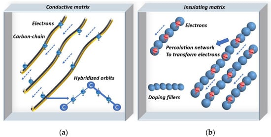
The processing of the extrinsic polymers focuses on doping the raw nonconductive material with a conductive material. When the concentration of added conductive fillers meets the percolation threshold, the conductive filler forms a percolation network that permits the electrons to move from one filler particle to another one [26]. This is also known as electron tunneling, which indicates the material has become conductive, which enables the conductivity of extrinsic polymers to be adjusted to achieve piezoresistivity [27].
Intrinsic polymers are named as such because of their hybridized orbits and special chemical bonds. Electrons connected by three sigma bonds can dwell in the p-z orbit. Thus, breaking the sigma bonds can release the restricted electrons, which can then transfer to the carbon chains. To achieve this purpose, suitable methods include doping particles into intrinsic polymers or heating. Therefore, the released electrons increase the conductivity of the material to achieve piezoresistivity [26,27,28]. Figure 2 illustrates the mechanisms of conductive intrinsic and extrinsic polymers.
1.2. Piezoresistive Sensing Mechanism of Conductive Ink
The general types of conductive ink include carbon nanoparticles, metallic compounds, and metal nanoparticles [29]. In pressure sensors, carbon nanotubes and metallic compounds are most frequently applied [16,17]. On the one hand, the resistivity of metallic particles is relatively lower than that of conductive polymers [29], producing increased piezoresistivity. On the other hand, carbon nanotubes possess high flexibility and stretchability [29]. Therefore, compounds of carbon nanotubes and metallic particles are suitable for piezoresistive force sensors.
Processing conductive ink to attain the piezoresistive effect is simple. This can be achieved by heating the material because high temperatures break the metal–carbon composites into metallic particles, which can transfer electrons. Another method involves inserting special particles such as Au or Ag into the solvent at a particular ratio to produce a conductive liquid solution for further fabrication such as combining carbon nanotubes in [29,30]. Using these two methods, the raw material can become conductive or semiconductive.
1.3. Piezoresistive Sensing Mechanism of Metal Liquids
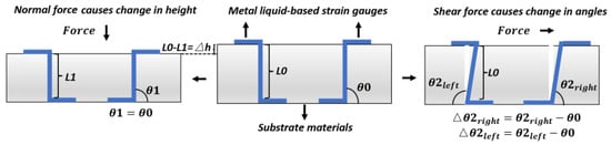
Unlike conductive ink and conductive polymers, metal liquids are naturally conductive. They are usually fabricated into strain gauges for force sensing. The working mechanism of metal liquid is determined by strain gauges, which show different deformations under force in multiple directions. Strain gauges are embedded in a substrate material, instead of being tiled over the substrates. In most current products, S-shaped strain gauges are fixed in symmetry but in opposing angles [31].
Constructing strain gauges with metal liquids enables the piezoresistive measurement of shear and normal forces [32]. Once an external force is applied, strain gauges present different deformations according to the direction of the force. For example, shear force causes strain gauges to show opposite deformation angles. With an applied normal force, they show the same deformation length, instead of being at angles to one another. Thus, their resistances alter differently [19,33]. As for the normal force, theoretically, when a normal force is applied, two gauges present the same change, and the output signals are the same [19,33]. The gauge-deforming process is demonstrated in Figure 3.
2. Piezoelectric Sensing Mechanisms and Suitable Materials
The phrase “piezoelectric effect” was first created in 1880 to describe the electric physical polarization phenomenon, which appears in the interaction between an external force and a non-centrosymmetric material [34]. The interaction process is principally influenced by the direction and strength of the external force. For instance, when vertically compressing a piezoelectric material, positive charges accumulate on the upper surface, while negative charges gather on the lower surface. Thus, polarization is formed. By connecting a polarized material with readout circuits, the electric signals reflect the change in applied force [35].
To quantify this effect, the following formula was established to describe the piezoelectric effect and correlation between polarization and imposed pressure:
where Pi represents the polarization of the materials in direction i, dij represents the piezoelectric strain factor, and σj represents the strain in direction j. The degree of polarization reflects the magnitude of the force.
For most application scenarios, polarization and force both appear in 3-dimensional directions, so d33 is most frequently used to assess the performance of a material and calculate the values of the force [36,37]. d31 is also used for measuring shear stress.
The material has opposite responses to tensing and compressing [35]. This indicates that the piezoelectric effect is reversible, and this feature has enabled the design of energy harvest systems [36]. Hence, this kind of system is suitable for long-time gait feature supervision [38].
Since 1880, several kinds of material have been developed as the sensing material in piezoelectric sensors. They can be chiefly classified into four types: natural biological materials, natural crystals, piezoelectric polymers, and piezoelectric ceramics [39].
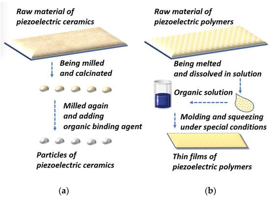
To fabricate force sensors, piezoelectric polymers and ceramics are most frequently used because their properties can be adjusted in synthetic processes according to demands [39,40,41]. In applications, the PSD process often involves bending and deforming. This requires sensing material to be flexible and stretchable. Additionally, to attain a high d33, materials should be small. To achieve these targets, piezoelectric ceramics are often milled into small particles, whereas piezoelectric polymers are usually transmuted into thin layers. We separately describe these processes in the following sections and Figure 4.
2.1. Piezoelectric Ceramics
Piezoelectric ceramics are brittle and rigid and are formed by large particles. Thus, they cannot be directly applied in PSD sensors because the process of detecting plantar force often involves bending and deforming. Therefore, materials should be designed to have high stretchability and piezoelectric coefficients [25,42].
The ceramic most commonly used for piezoelectric force sensors is PZT (Pb[Zr(x)Ti(1−x)]O3). The manufacture of PZT can be divided into four steps: First, the raw PZT material is wet milled, which uniformly distributes the proportions of the ingredients. Second, the obtained particles are dried for further calcination, which is conducted in a pure chemical environment to prevent contamination. Third, after being calcinated under high temperature, for instance, around 1000 °C, the desired PZT phase is produced [43]. Fourth, the powders are milled again to ensure homogeneity and prepare them for the adjunction of an organic binding agent. Finally, the water in the composites evaporates, which indicates that the PZT for the piezoelectric sensor has been fabricated [43].
2.2. Piezoelectric Polymers
The rigidity of ceramics hinders the stretchability of PSD sensors. To address this issue, organic piezoelectric polymer-based thin films were designed. Their merits include mechanical durability and flexibility. The most representative material is PVDF, which is the material we consider in the following paragraphs to demonstrate the physical manufacturing process of piezoelectric polymers.
The fabrication of PVDF can be briefly described as radically polymerizing monomer vinylidene difluoride at 10–150 °C and 10 to 300 atm. Polymerization can be divided into four steps [44,45]: First, the raw material is melted. Melted products are shaped in molds of the desired shapes at a relatively higher temperature. Second, the molded and cooled products are dissolved in a suitable solution to obtain the desired chemical properties. The solvent is evaporated from the composites, resulting in the final product having a porous shape. Third, the polymers are transformed into thin films. In this step, polymers are processed in a high-pressure environment and electric fields. Finally, the polymers are squeezed into thin films for further production of piezoelectric sensors [45,46,47].
This entry is adapted from the peer-reviewed paper 10.3390/ma15144837
This entry is offline, you can click here to edit this entry!