Your browser does not fully support modern features. Please upgrade for a smoother experience.
Please note this is an old version of this entry, which may differ significantly from the current revision.
Subjects:
Medical Laboratory Technology
Nerve stimulation is an effective method to alleviate the negative impacts of neurodegeneration. According to nerve categories, nerve stimulation can be divided into three types—brain stimulation, spinal spur, and peripheral stimulation. All three therapies take similar physical principles to achieve stimulus, while WPT and wireless telecommunication are adopted to maintain a relatively long duration and precise control.
- nerve stimulation
- drug delivery
- wireless charging
- medical devices
1. Deep Brain Stimulation
Deep brain stimulation is a therapy that aims to ameliorate the impacts of neurodegeneration, which can cause neuron death and a series of diseases, such as Alzheimer’s, Parkinson’s, and amyotrophic lateral sclerosis [11]. Also, focal brain stimulation, which is categorized under brain–machine interface (BMI), is renowned as one form of neuro-stimulation. This is achieved by providing the spur with an electrical signal [12]. Currently, there are two methods of stimulation—conventional electrical stimulation and optogenetic stimulation [13]. Although their biochemical processes are different, both systems require an initial electricity input and follow electrical waves or light illumination. Based on shared demand, it can be concluded that the development of BMI requires a method to extend the lifetime of the system while maintaining the sensitivity of the brain.
One study [14] developed an inductive coupling WPT system for brain implants with minimized mismatch loss, which had a relatively small size of the receiving coil. This design provided a rechargeable implant that could increase the frequency of wireless telemetry with power guarantee. The primary coil obtained a circular feature with an inner diameter (D) of 12 mm and a trace width (w) of 3 mm. There was also a differential feed gap (G) of 3.175 mm for laminating on a two-layer FR4 substrate. For the secondary coil, the shape was similar to a cube with a length (L) of 1 mm, with an inner gap (V) of 0.8 mm and a differential feeding gap (GL) of 0.9 mm, as shown in Figure 1. The whole system had an operating power gain of 0.1% with a transmitting distance of 15 mm (Δd). The in vitro test was held in a developed cerebral spinal fluid (CSF) phantom with an optimal frequency of 400 MHz, which belonged to the Medical Device Radiocommunications (MedRadio) Service core band for general diagnostic and therapeutic applications [15].
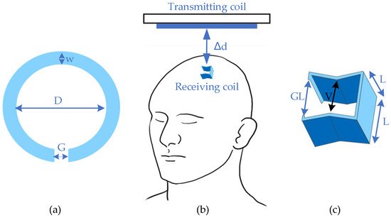
Figure 1. Design of deep brain stimulator. (a) Transmitter; (b) general view; (c) receiver.
In addition, other related designs of recent deep brain implants are given in Table 1, which summarizes the current development trends and opportunities. For the wireless power link itself, the crucial parameters are the power transfer efficiency (PTE) and output power. These two criteria illustrate the sufficiency of power supply, which is the cornerstone of the feasibility of the system. When applying WPT in implants, safety issues including radiation and heating effects are also essential. However, not all studies of evaluations include these two parameters, especially heating impact. Here, only specific absorption rate (SAR) is summarized as the factor for safety assessment. In addition, it should be noted that the other parameters, such as size, weight, etc., might be the key parameters to evaluate the system in practical situations. However, this paper mainly uses PTE and output power as the key parameters due to easy evaluation. Only a few studies have discussed SAR impacts due to the lack of in vivo testing and human body simulation. There is therefore no detailed summary of safety issues in this section. In addition, the encapsulation material and media simulation are also discussed here to demonstrate the current safety concerns and mitigation strategies. According to Table 1, the PTE for deep implants is relatively low but the output power sufficiently supplements the implanted battery, which is generally designed with a relative size [16,17].
Actually, there are two studies that show a high PTE, and their testing scenarios include the air as the transmitting media. In fact, the power loss caused by electronics devices in small implants is quite significant, which greatly leads to the large difference for different transfer systems. Moreover, the WPT design, the distance involved, the coils used, the material of the implant, the size, the power level, the transfer frequency, etc. all greatly affect the PTE of the prototype. Additionally, the power requested in a regular period of stimulus is lower than the power input. Furthermore, in vivo or in vitro tests are adopted by most of the researchers to enhance the reliability of safety evaluation.
Based on the abovementioned parameters, WPT in deep brain therapy obtains great research potential.
- (1)
-
Convenience enhancement: Analyzing deep brain activities can be easier than before. With two transmission strategies, namely a wearable energy supplier or a recharge cage, it can allow the object to move freely during the charging period.
- (2)
-
Potential for full implantation: Fully embedded devices have become the mainstream of the brain research field. Due to the difficulties in plug-in charging and minimization, WPT offers an efficient alternative for practical applications.
- (3)
-
Possibility for stretchable implants: Flexibility of coil structure ensures the possibility of applying the stretchable optogenetics system [18].
However, there are also several limitations of WPT applications in deep brain therapy.
- (1)
-
Minimization difficulty: In order to protect other parts of the brain, the overall size of the implants needs to be small enough. Aside from difficulties in minimizing the functional parts of devices, materials and techniques for downsizing powering sections are still under development.
- (2)
- (3)
-
Complicated transmitting gap characteristics: It is difficult to align the results of simulations and in vitro and in vivo tests, since the characteristics of biological tissues are hard to determine, especially when these characteristics vary between individuals.
The future development is also draw as below:
- (1)
-
Development of new materials and energy storage techniques will accelerate WPT application in implants: Nano super-capacitors and GaN-based capacitors can be used to store energy from a harvesting source, such as piezoelectric nanowires [23].
- (2)
-
Combination of wireless communication and power transfer: Brain implants generally aim for activity analysis, and the combination of two main functions could downsize these devices.
- (3)
-
Some new topologies of WPT can be adopted in deep brain therapy, which could significantly improve the PTE and the output power, as well as the therapy effect.
2. Peripheral Stimulation
The principle of peripheral stimulation is similar to the cortical spur, while it focuses on recovering the dysfunctional limbs and sensors. This section classifies the peripheral stimulation into three parts, based on the nerve category.
2.1. Vagus Nerve Stimulation
General peripheral nerve implants refer to the devices that rebuild the dysfunctional motor and sensory functions in the limbs with patterned stimulation [6]. This kind of application requires precise data collection and long-term operation in order to avoid further damage to nerves and muscles [24]. In order to meet these requirements, the implanted system adopts the analogous characteristics of deep brain stimulators, although the locations are different. Similarly, the chargers are designed to be wearable and tolerant of misalignment.
Table 1. Comparison of wireless power transfer (WPT) in deep brain stimulation.
| Category | Frequency | Input 1 | Output 2 | Efficiency 3 | Transmitting Distance | Transmitting Coil | Receiving Coil | Material/Encapsulation 4 | Media | ||
|---|---|---|---|---|---|---|---|---|---|---|---|
| Cortical [25] | 907.5 MHz | 20.1 mW | 15.6 µW | ~0.04% | 16 mm = 11benearth+ 5air | Annulus: Douter = 41.3 mm Dinner = 10 mm | Cubic: L = 1 mm | PDMS | Head equivalent phantom | ||
| Cortical [25] | ISM band | 26.8 mW | 15.6 µW | ~0.05% | 32 mm = 20bone+5fat+2skin+5air | Annulus: Douter = 41.3 mm Dinner = 10 mm | Cubic: L = 1 mm | PDMS | Porcine measurement | ||
| Cortical [25] | 907.5 MHz | ~29 mW | 118 µW | ~0.4% | 16 mm = 11benearth+ 5air | Annulus: Douter = 41.3 mm Dinner = 10 mm | Planar square: L = 6.5 mm | PDMS | Man’s Head model | ||
| Cortical [15] | 400 MHz | 19 mW (SAR1g), 82 mW (SAR10g) | 100 mW | 0.1% | 15 mm = 12benearth+ 3air | Annulus: Dmean = 12 mm | Approx. cubic L ~ 1 mm | medical grade silicone & Parylene C | Porcine tissue & Mice back | ||
| Optogenetic [26] | 13.56 MHz | N/A | N/A | 0.56% | Movable 6 | Cuboid: 40 cm × 40 cm × 20 cm | Planar square: L = 10 mm | medical grade silicone & Parylene C | Porcine tissue & Mice back | ||
| Optogenetic [27] | 7.2 MHz | N/A | N/A | 3.16% | 15 mm = 12benearth+ 3air | Planar square: L = 10.5 mm | Planar square: L = 10.5 mm | medical grade silicone & Parylene C | Porcine tissue & Mice back | ||
| Cortical [14] | 400 MHz | 19 mW (SAR1g), 82 mW (SAR10g) | 100 mW | 0.1% | 15 mm = 12benearth+ 3air | Annulus: Dmean = 12 mm | Approx. cubic L ~ 1 mm | medical grade silicone & Parylene C | Porcine tissue & Mice back | ||
| Cortical [28] | 400 MHz | 18 mW | 57 µW | 0.32% | 10 mm | Annulus: Douter = 18 mm Dinner = 12 mm | Approx. cubic L ~ 1 mm | medical grade silicone & Parylene C | Man’s Head model & CSF | ||
| Deep brain [7] | 403 MHz | ~99 mW | 10.52 mW | 10.62% 7 | 5 mm = 3benearth+ 2skin | Annulus: Dmean = 19.86 mm | Annulus: Dmean = 15.94 mm | N/A | N/A | ||
| Deep brain [26] | 13.56 MHz | 0.5 A | 8.5 mW | 0.56% | Movable 6 | Cuboid: 40 cm × 4 0 cm × 20 cm | Approx. cubic L ~ 1 cm | LTPS TFTs | 1X PBS | ||
| General [29] | 120 kHz | 9 V | 16V/250 mW | N/A | Movable 6 | Annulus: Douter = 44 mm Dinner = 8 mm Thickness = 1 mm | Annulus: Douter = 22 mm Dinner = 18 mm Thickness = 0.5 mm | N/A | Air | ||
| General 5 [30] | 160 MHz | N/A | 60 mW | 60% 8 | Movable 6 | Annulus: Douter = 35 mm Dinner = 34.4 mm | Annulus: Douter = 15 mm Dinner = 14.8 mm | Annulus: Douter = 10 mm Dinner = 9.8 mm | N/A | Air | |
| General [31] | 13.56 MHz | 12 W | 50 mW/mm2 | N/A | Up to 30 cm | Two Planar squares: L = 30cm Distance = 9 cm | Annulus: Douter = 9.8 mm Thickness = 18 µm | Uniform bilayer of parylene; PDMS | In vivo test (mice) | ||
1 Input unit is changed due to the information provided from related research works. 2 Output power is defined as the activation power of micropump or metal melting. 3 Due to the ambiguous input and output power, the power transfer efficiency of most links cannot be calculated. 4 Coating refers to the material used to separate tissue and implanted devices, while encapsulation refers to the material used to envelope the circuits. 5 This design obtains an intermediate antenna for the high power-transfer efficiency. 6 “Movable” refers to a patient or research target that can move freely with receiving coils during charging. 7 This design uses a stretchable wire for receiving coil. 8 The efficiency is for wireless links but not for the overall systems. The high values are equal to l.
Figure 2 demonstrates the research work [24] that developed a system containing a bio-electronic interface that links the injured muscle/nerve and the peripheral muscle in order to restore dexterous function. This process is achieved by connecting the proximal end of the injured part to the distal end of the peripheral nerve with an electromyography (EMG) signal. The telemetry is maintained by a wireless system with power offered from another coil. For WPT, the primary and secondary coils have a square design with a side length (L) of 16 mm. The link can provide 5 V to power the implanted amplifier with a frequency of 13.56 MHz. This design can control stimulation with data feedback. Other mature systems, such as ReStore, provide the pulse with pre-designed programs [32,33,34].
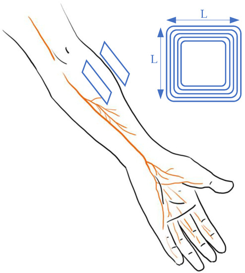
Figure 2. Design of vagus nerve stimulation in arms.
2.2. Retinal Nerve Stimulation
Retinal prostheses are widely adopted and promising therapies for eye-handicapped patients with common outer retinal degenerative issues, including age-related macular degeneration (AMD) and retinitis pigmentosa (RP) [29,35,36]. These problems are the dominant causes of most retinal blindness, especially in developed countries with an aging population [37]. For patients, visual function is maintained through an electrical stimulus on intact neural cells. Incitement is provided by implanted electrodes that deliver the surrounding images captured by a miniature digital camera mounted on eyeglass frames [37,38,39]. Due to the structure and characteristics of subretinal and epiretinal areas and nerve systems, both power and data are transmitted wirelessly to minimize the size of implanted devices and hazardous impacts. Generally, retinal recovery is categorized into two methods based on the implanted location; subretinal access ensures a better alignment, while the epiretinal approach is easier to be implanted [36]. The major consequence of the different locations of the wireless system is the change of media material, which could affect the coil coefficient and further dwindle the PTE.
Wong et al. [31] proposed an innovative retinal implanted device. It replaced a traditional primary power supply with a photo-sensing circuit that adopted a phototransistor and a ring oscillator to provide stable power for wireless telemetry and power transfer. The design of the WPT system, which is shown in Figure 3, is different from previous studies on antenna design. The primary antenna is a circular Litz coil with a diameter of 3.0 cm (D1) and four windings, while the secondary coil is a thin aluminum film consisting of 100 windings with a total length of 2.8 m. The power is transmitted through magnetic resonance coupling with a frequency of 160 MHz. According to the study’s outcomes, the maximum power transfer efficiency was around 25% based on the energy requirement as 320 µW of a photo-sensing circuit that is integrated with receiver antenna and other receiving-side elements in the eyeball. The system was also tested via an in vitro experiment in phosphate-buffered saline (PBS). It turned out that the artificial units could provide the same stimulus as a living retina.
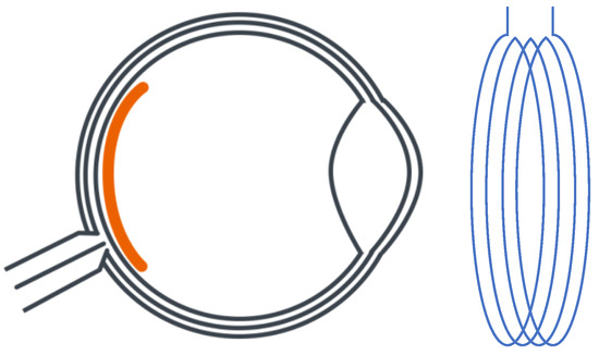
Figure 3. Planning design of retinal neurostimulator.
In addition to improvements in energy resources, the overall system has been updated in recent years, especially for the circuit design. To further illustrate current research emphasis and future development directions, a summary of WPT for retinal devices is presented in Table 2, below.
From Table 2, in order to follow the trend of transmission efficiency and safety improvement, several research groups [36,39,40,41] enlarged the receiver coil by relocating the secondary antenna from the back to the anterior. Meanwhile, hermetic packaging was used to coat for the encapsulation with biocompatible materials. Due to this relocation, the coil design changed to fulfill minimization requirements, as the implanted coil was wound as a spiral for the curvature of the eyeball. Additionally, current research also seeks to enhance the efficiency and safety aspects of misalignment tolerance [29] and converter improvements [28]. Another study focuses on recovering the sense of dark and bright (instead of regaining vision) with the wireless system to power up the artificial retina [42].
Table 2. Comparison of wireless power transfer in retinal prosthesis.
| Category | Frequency | Input 1 | Output 2 | Efficiency 3 | Transmitting Distance | Transmitting Coil | Receiving Coil | Material/Encapsulation 4 | Media | ||
|---|---|---|---|---|---|---|---|---|---|---|---|
| Subretinal [40,41] | 125 kHz | ~100 mW | 0.76 mC/cm2 for 16 pulses/s | N/A | 20 mm | Annulus: Douter = 41.3 mm Dinner = 33.7 mm | Annulus: Douter = 10.3 mm Dinner = 8.3 mm | Flexible polyimi-de substrate & Silicon | Air & phosphate buffered saline solution & minipig | ||
| Subretinal [36,37,39] | 125 kHz | ±2.5 V | N/A | N/A | 30 mm | Annulus: Dmean = 19 mm | Spherical D = 19 mm T = 2 mm | Polydimethylsiloxane (PDMS) & Titanium | Air & phosphate buffered saline solution & minipig | ||
| Subretinal [35] | 160 MHz | N/A | 320 µW | N/A | 1 cm | Dmean = 60 mm 4 windings | Tot. Length = 100 m 100 windings | LTPS TFTs | 1X PBS | ||
| General [28] | 1 MHz | 9V | 16V/250 mW | N/A | 7 mm | Annulus: Douter = 44 mm Dinner = 8 mm Thickness = 1 mm | Annulus: Douter = 22 mm Dinner = 18 mm Thickness = 0.5 mm | N/A | Air | ||
| General 5 [29] | N/A | N/A | 60 mW | 60% | 7 mm | Annulus: Douter = 35 mm Dinner = 34.4 mm | Annulus: Douter = 15 mm Dinner = 14.8 mm | Annulus: Douter = 10 mm Dinner = 9.8 mm | N/A | Air | |
| General 5 [43] | 10 MHz | N/A | 25 mW | 36% | 21 (outside)+4 (inside) mm | Annulus: Douter = 42 mm Dinner = 34.4 mm | Annulus: Douter = 20 mm Dinner = 14.8 mm | Annulus: Douter = 10 mm Dinner = 9.8 mm | N/A | Air & saline | |
1 Input unit is changed due to the information provided from related research works. 2 Output power is defined as the activation power of the micropump or metal melting. 3 Due to the ambiguous input and output power, the power transfer efficiency of most of the links cannot be calculated. 4 Coating refers to the material used to separate the tissue and implanted devices, while encapsulation refers to the material used to envelope the circuits. 5 This design obtains an intermediate antenna for high power-transfer efficiency.
From the above analysis, WPT shows a great potential in retinal prosthesis from the following three aspects:
- (1)
-
Minimization can be maintained with the flexible design of coils, while the wireless system obtains the functions of both power transfer and data telemetry;
- (2)
-
The duration can be extended with the current photo-sensing circuit by the consistent power input;
- (3)
-
Safety is guaranteed with the hermetic design and biocompatible materials.
Also, due to the special conditions of retinal use, the application of WPT has the following difficulties:
- (1)
-
Difficult implantation surgery: The non-planar structures of the target organs indicate a possible bending of receiving antenna, which would lead to relatively low power transfer efficiency.
- (2)
-
Misalignment concerns: For devices designed to recover vision, it is hard to ensure alignment due to the 360° rotation ability of eyeballs, as the primary coil is fixed on wearable glasses while the receiving antenna is implanted inside the body. However, symmetry can be maintained with a secondary coil located with a certain degree and spot, while the regained vision is limited.
- (3)
-
Change in transmission gap: Subretinal implantation is adopted for the majority of devices, as this ab externo surgery obtains a minimally invasive influence. However, the structure and composite of the retina could change with external impacts and age, which would lead to unexpected changes in electromagnetic permittivity and permeability.
Based on the previous analysis, the future of WPT in retinal implants can be indicated as follows:
- (1)
-
Alignment improvement: Techniques with a high tolerance for misalignment and rotation will be developed. A combination of different coils to replace a singular receiver might be adopted. The strategies are also requested to maintain the low hazardousness and high convenience.
- (2)
-
Self-powered design: Reuse the received light to power up the system.
- (3)
-
Minimization of implanted electrodes: To increase the preciseness of stimulation and data analysis, the number of electrodes would increase under the constraints of mass and size.
2.3. Cochlear Nerve Stimulation
As a mature implant technology [44,45,46,47,48], the cochlear implant has experienced a long development path [49] as the first commercial wireless powered implantable device [50]. Generally, cochlear implants require both wireless communication for auditory information transmission and wireless power transfer to extend operation duration [50]. In order to meet all these requirements, implanted coils can realize all functions within a small space. For information transmission, the outside components, which are usually attached behind the ear, can capture the sound with microphones and transfer the information to electrical signals with a signal processor. Then, the signals can be transmitted to inner implants through wireless telemetry. After that, the implanted coil generates the electricity that stimulates the existing auditory nerve fibers to deliver the information to brain [51,52]. The implanted stimulator unit, which interprets the sound to electrical signals, is powered by a battery located outside the ear. This battery can be designed with rechargeable characteristics to continuously supply energy via WPT [53]. According to the commercial design, the coil distance is several millimeters, as they are merely separated by skin [54]. With this relatively small transmitting distance and simple gap texture, the coil link can maintain a high power-transfer efficiency with near-field magnetic resonance or inductive coupling [49]. As the power requirement ranges from 20mW to 40mW [49,55,56], the relatively small coils are sufficient for the power input. The general design for the WPT link for cochlear implants is presented in Figure 4.
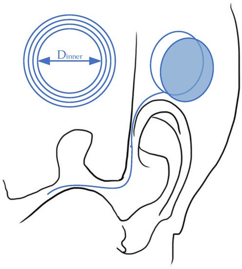
Figure 4. Wireless power transfer for a cochlear implant system.
For cochlear implants, there is no table summary for WPT development focuses over the last 10 years. Currently, this kind of biomedical device has been promoted to the market, while the major developments with regard to WPT are illustrated by patents rather than research papers [8]. Moreover, the wireless link for the cochlea nerve emphasizes more on telecommunication rather than power transmission [57]. For WPT technology, the parameters are similar to the example above, as the structure of support devices is highly restricted. For the health impacts, long-term exposure to radiation can lead to unpredictable hazardous effects due to changes in DNA or gene scale [58]. The potential ramifications are the degradation of the neuroendocrine system [59], fertility decrease, and muscle stiffness with loss of protein [22].
3. Spinal Stimulation
Similar to nerve stimulation, spinal nerve stimulation aims to assuage pain or dysfunction due to spinal cord injury. To be more specific, epidural spinal cord stimulation (ESCS) focuses on locomotor recovery for patients with incomplete spinal cord injury and multiple sclerosis [60]. Although the biochemical principles are different from previous therapies, the wireless link is designed with high similarity. To avoid redundancy, spinal stimulation is investigated without a table summary, due to there being relatively fewer applications than the other nerve therapies.
One high-efficient magnetic resonant WPT for spinal cord stimulation [61] utilized the unconventional multi-sine (MS) transmission waveform, which achieves an overall system efficiency of 50.7% with 6.78 MHz. The wireless link is designed with a four-coil system, with two planar circular coils at each side. For the transmitter, the inner length and width of the driven coil are 18 mm (D2) and 6 mm (w2), respectively, while the primary coil with 21 mm (D1) inner diameter and 27 mm (w1). For the receiver side, the parameters of the load coil are 18 mm inner and 20 mm outer, while the secondary coil is 8 mm inner and 20 mm outer. The transmitting distance is set as 18 mm, which is simulated as fat and skin in an in vitro test. Generally, the wireless link is located with a pulse generator placed in a pelvic or thoracic cavity [62]. This research work is designed to charge right after the spine, which is shown in Figure 5.
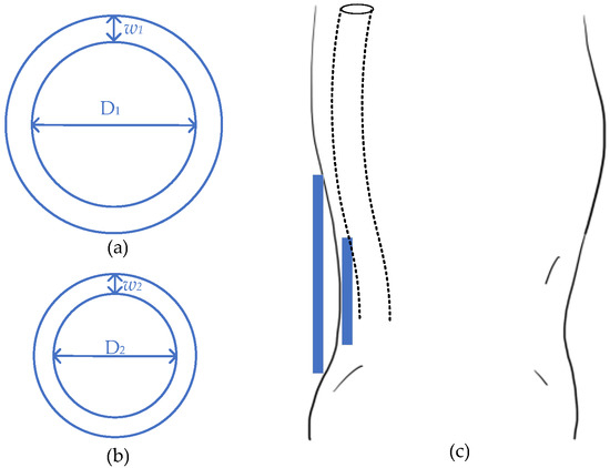
Figure 5. Design of spinal stimulator. (a) Transmitter; (b) receiver; (c) general view.
Compared to other stimulations, the spinal cord spur illustrates a flexible WPT location, especially compared to deep brain stimulation. The spinal cord, which is across the whole back, has plenty of options to locate the implant, while the pulse generators can be set near to the skin to achieve high energy-transfer efficiency. However, the healing targets of this stimulus are duplicated by brain implants, while the latter can maintain more functions. The current research of this kind of spur is still limited, but it will likely flourish in the future.
For WPT application, various location choices assure efficiency enhancement. The unconventional MS transmission [61] waveform could be utilized to enhance efficiency without considering a high increase in specific heat absorption. Duplex amplitude-shift keying (ASK) [63] and load-shift keying (LSK) [60] communication can also be applied to improve the power and data transmission efficiency, respectively. Additionally, the soft and stretchable coils are also attractive for muscle movement concerns [18].
This entry is adapted from the peer-reviewed paper 10.3390/en13112837
This entry is offline, you can click here to edit this entry!