Your browser does not fully support modern features. Please upgrade for a smoother experience.
Please note this is an old version of this entry, which may differ significantly from the current revision.
Offshore structures exist in a variety of forms, and they are used for a variety of functions in varied sea depths. These structures are tailored for certain environments and sea depths and other design considerations.
- offshore structure
- offshore platform
- fixed platform
- floating platform
1. Introduction
Oil and gas facilities include offshore structures and onshore structures, onshore oil tanks, as well as both downstream and upstream assets [1,2,3]. Although offshore wind farm facilities are renewable energy facilities, while Very Large Floating Structures (VLFS) could have offshore applications, they are sometimes classified as offshore structures. However, the main categories include fixed and floating offshore structures [4,5,6]. Fixed offshore structures, monopods, and guyed wire caissons are examples of offshore structures. In the same vein, complex deep water assets such as Floating Production and Storage Offloading (FPSO), Mobile Offshore Production Unit (MOPU), Tension Leg Platform (TLP), and semi-submersible structures, are also examples of offshore structures. Advances in ocean engineering are currently being undertaken, with a variety of new offshore structure designs spanning from fixed platforms to floating platforms [6,7,8,9,10]. These offshore platforms can also be used for dynamic positioning, exploratory activities, drilling/production, navigation, ship (un)loading, fluid transport, and bridge support [11,12,13,14,15,16]. Hence, the facilities on the offshore structures require project management, asset/facilities management, and general maintenance. In addition, there are supporting attachments for these offshore installations that are used for a variety of functions and in a variety of water depths and environments globally. These components included drilling/production marine risers [17,18,19,20,21,22,23], composite risers [24,25,26,27,28,29,30], mooring lines [31,32,33,34,35,36,37,38,39], and marine hoses [40,41,42,43,44,45,46,47,48,49]. Figure 1 depicts some offshore platform installations.
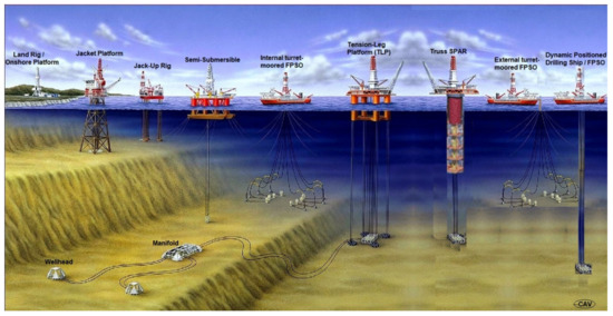
Figure 1. Different types of deep-water offshore facilities for drilling and production, showing land rig/onshore platform {10–100 m}, conventional fixed platforms{150–412 m}, jacket platform {150–412 m}, semisubmersibles {457–1920 m}; floating production, storage and offloading (FPSO) unit {1345–1500 m}; tension leg platform (TLP) {457–2134 m}; Truss SPAR {610–3048 m}; subsea wellhead, completion and tieback to a host facility, and subsea manifold.
Offshore platforms have been employed in a variety of aquatic situations and could be used as artificial reefs for many years. As a result, designing and maintaining them is incredibly challenging. Hence, careful consideration should be given to the design and maintenance of offshore structures in order to avoid early decommissioning, significant corrosion hazards, oil spillage, and other permanent environmental damage. Different activities for proper equipment selection [50,51,52,53,54,55,56,57], design of platform types [58,59,60,61,62,63,64], engineering management of well bores [65,66,67,68,69,70,71,72,73], and other drilling/production procedures [74,75,76,77,78,79,80] are required for the uses of these off-shore structures. One of the most obvious of these applications is offshore oil production, which presents a substantial challenge to the product designer or offshore engineer [81,82,83]. Environmental loadings [84,85,86,87,88], hydrodynamics [89,90,91,92,93,94,95,96], hydroelasticity [97], corrosion [98], failure analysis [99], ocean wave mechanics [100,101,102,103,104,105,106,107,108], fluid content loadings [109,110,111,112,113,114,115], fatigue limits [116,117,118,119,120], reliability [121,122,123,124,125,126,127,128], and so on are all factors to consider during the design process. As a result, the designer must ensure that the product is safe, stable, has a high fatigue resistance, has a long service life, and is cost-effective for the customer. Secondly, it is important that these offshore structures have high service life to ensure sustainability and durability, so that the oil producers can produce enough oil and gas products to meet the global demand. Figure 2 shows the daily demand for crude oil globally, showing dependence on fossil fuels.
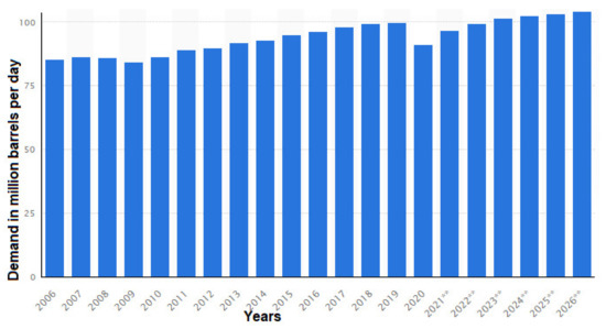
Figure 2. Daily demand for crude oil worldwide from 2006 to 2020, with a forecast until 2026 (in million barrels per day) {** shows the predicted daily demand from the forecast} (Courtesy: IEA & Statista, data retrieved in 2021).
Since offshore structures are exposed to extremely harsh marine environments and changing sea depths, these offshore assets must generally run securely for at least twenty-five (25) years. As a result, the designs are carried out using peak loads generated by hurricane wind and waves during the platform design life [129,130,131,132,133,134,135]. In addition, fatigue loads induced by waves over the platform’s lifetime, as well as platform motion, are all essential design challenges addressed by standards [136,137,138,139,140,141,142,143,144,145,146,147,148,149,150,151,152]. Strong currents can occasionally impact the platforms, putting the integrity of the entire system at a threat, hence the need for designing offshore structures against harsh weather conditions [153,154,155,156,157]. To ensure the integrity of the structure is maintained, monitoring is essential for the design [158,159]. Furthermore, the scale of an offshore structure is considered during the design for its stability and hydrodynamics [159,160,161,162,163]. The material density is also taken into account in the design. The majority of offshore platforms are built in shipyards using enormous steel or in-situ using concrete, as is the case with gravity-based structures. These fixed and floating offshore constructions are mostly utilised for energy generating or oil production, while some are used as breakwater devices and wave-energy converters (WECs) [164,165,166,167,168,169,170,171,172,173]. Offshore platforms can be small or massive, depending on the functionality. However, offshore structures are recorded as among the world’s highest man-made structures built. Also, the material grade must have high corrosion resistance to be used in ocean environments, such as high-grade steel [174,175,176,177,178,179]. The oil and gas are separated on the platform and transported to shore via pipelines or tankers [180,181,182,183,184,185,186,187,188,189,190,191,192]. The lifting, transportation, installation, design, fabrication, and commissioning of these offshore platforms must all be carefully planned to meet these goals [193,194,195,196,197,198,199,200,201,202,203]. The foundation of this semi-submersible in deeper waters requires excellent payload integration [204,205,206,207,208,209,210,211,212] for minimal motion responses across all degrees of freedom (DoF) due to the direction of the superstructure [213,214,215].
2. Design Considerations
The development and design of floating and fixed platforms are based on some design criteria. All operating considerations and environmental data that potentially affect the platform’s detailed design are included in the design parameters discussed here.
2.1. Operational Factors
2.1.1. Location
Before the design is finished and the work is completed on the engineering design layout, the platform’s position should be determined. Environmental circumstances vary by location; within a particular geographic area, foundation conditions, as well as design wave heights, periods, and tides, will differ. Figure 3 shows some floating structures like the drilling barge used during early explorations in the Gulf of Mexico (GoM), USA. The details of some platforms are given in Table 1.
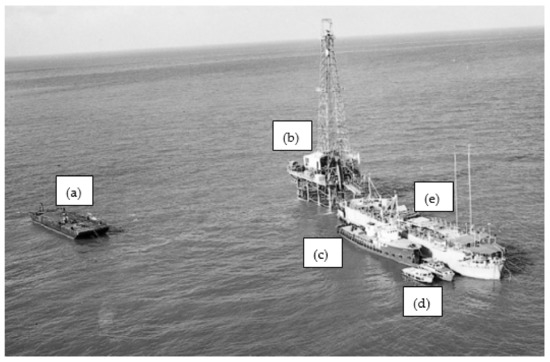
Figure 3. Drilling structures used during early explorations in the Gulf of Mexico (GoM) showing (a) floating barge, (b) typical offshore drilling rig, (c) service vessel, (d) tugboat, and (e) FPSO vessel.
Table 1. Some deep sea facilities with installation details.
| Platforms | Sea Depths | Installed Years | Platform Type | Oil Field |
|---|---|---|---|---|
| Perdido | 2450.0 m | 2010 | SPAR | GoM |
| Thunder Horse | 1841.0 m | 2010 | SemiSubmersible | GoM |
| Magnolia | 1400.0 m | 2003 | ETLP | GoM |
| Mad dog | 1311.0 m | 2005 | SPAR | GoM |
| Bonga | 1000.0 m | 2005 | FPSO | Nigeria |
| Marlin | 988.0 m | 1999 | TLP | GoM |
| Ram-Powell | 980.0 m | 1997 | TLP | GoM |
| Olympus | 914.0 m | 2014 | TLP | GoM |
| URSA | 1204.0 m | 1999 | TLP | GoM |
| Mars | 896.0 m | 1996 | TLP | GoM |
| Auger | 872.0 m | 1993 | TLP | GoM |
| Jolliet | 536.0 m | 1989 | TLP | GoM |
| Bullwinkle | 412.0 m | 1988 | Fixed Platform | GoM |
| Appomattox | 2195.0 m | 2019 | Semisubmersible | GoM |
| Na Kika | 1829.0 m | 2003 | Semisubmersible | GoM |
| Atlantis | 2134.0 m | 2007 | Semisubmersible | GoM |
| Heidrun | 351.0 m | 1995 | TLP | GoM |
| Snorre | 310.0 m | 1992 | TLP | North Sea |
| Cognac | 304.0 m | 1978 | Fixed Platform | GoM |
| Hutton | 148.0 m | 1984 | TLP | North Sea |
| Vito | 1189.0 m | 2022 | Semisubmersible | GoM |
| Argos | 1311.0 m | 2022 | Semisubmersible | GoM |
2.1.2. Function
Drilling, producing, storing, materials processing, living quarters, or a combination of these are the most common functions for which a platform is created. A study of the layouts of equipment to be located on the decks should be used to decide the platform configuration. Before deciding on final dimensions, the clearances and spacing of equipment should be carefully considered. Function determines the classification of the offshore structure. The function of jack-ups could be for drilling or decommissioning or the installation of wind turbines. Figure 3 shows the floating drilling barge used in early explorations in the Gulf of Mexico (GoM), USA.
2.1.3. Orientation
The platform’s orientation refers to its location in the design with respect to a fixed axis, such as true north. The direction of prevailing seas, winds, and currents, as well as operational requirements, are frequently used to determine orientation.
2.1.4. Water Depth, Waves and Current
Following the increased need for energy, fossil fuels have recently gained market share from various energy sources. However, both renewable energy sources and non-renewable energy sources have competed fairly based on the use of onshore and offshore platforms. To choose the right oceanographic design parameters, information on sea depth, ocean waves, current and tides is required. The water depth should be as precise as is feasible so that elevations for fenders, decks, boat landings, and corrosion protection may be set. Floating offshore wind turbines (FOWTs) are also designed by considering the water depth, waves and current. Some of the newer offshore platforms contain advanced technologies derived from existing offshore platforms employed in oil and gas development. Some wind turbines have foundations designed based on other platforms like semisubmersibles [213,214,215,216,217,218,219,220]. For breakwater and wave energy devices, they require shallower water depths. However, these devices have been able to operate under a diverse range of wave environments as seen in the diverse range of technologies, and devices such as the single column and multi-column wave energy converters (WECs) [164,165,166,167,168,169,170,171,172,173].
2.1.5. Deck Elevation
When waves contact a platform’s bottom deck and equipment, they produce large forces and overturning moments. Unless the platform is intended to withstand these forces, the deck’s height should be sufficient to offer appropriate clearance above the design wave’s crest. Additionally, an “air gap” should be considered to allow for the passage of waves greater than the design wave. There are some guidelines for the air gap.
2.2. Environmental Factors
API and other relevant industry standards include general meteorological and oceanic factors such as in API WSD 2000 Cl. No. 1.3.1 and API RP-2MET-INT [153,154,155,156]. When establishing the relevant meteorological and oceanographic parameters impacting a platform location, experienced specialists should be engaged. The sections that follow provide a broad overview of the information that may be necessary. After consulting with both the platform designer and a meteorological oceanography specialist, the information needed at a place should be chosen. Data from measurements and/or models should be statistically examined to provide the necessary descriptions of typical and extreme environmental conditions.
All relevant information on the environmental data used should be meticulously documented. The estimates on the structural reliability, fatigue life prediction and the source for all design data should be noted for validation, verification, trustworthiness, and dependability. Lastly, both the parameters used and the methodology listing all the procedures used to convert existing data into desired environmental values should be recorded. Typical environmental conditions are seen in the North Sea’s weather conditions where the Transocean Enabler semisubmersible drilling rig operates (see Figure 4).
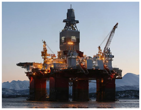
Figure 4. Transocean Enabler semi-submersible drilling rig built in 2016 and designed to operate in harsh environments (Courtesy: Transocean).
2.3. Loading Factors
In ocean engineering, the term “environmental load conditions” is used in the design of offshore structures and other marine structures to include wind, waves, currents, and tides, depending on the environment under consideration. Operating environmental load conditions are the forces placed on the structure by a minor occurrence that is not severe enough to obstruct normal operations as stipulated by operators. The forces imposed on the structure by minor events that are not harsh enough to hinder any normal operation, as prescribed by the operators, are known as operating environmental load conditions. The forces placed on the platforms by the selected design scenario are known as design environmental load conditions. Design loading conditions are introduced as seen in industry standards, such as API-WSD 2000 Cl. No. 1.3.1 and API 2MET-INT, to design these structures.
The platform should be built to withstand the loads that will have the most severe consequences for the construction. The following loading conditions should be included in the loading conditions: environmental conditions, as well as appropriate dead and live loads:
-
Operating environmental parameters, including dead loads and maximum live loads, that are appropriate for the platform’s usual operations;
-
Operating environmental parameters, including dead loads and minimum live loads that are adequate for the platform’s usual operations;
-
Establish environmental factors in the design with maximum live loads and dead loads that can be combined with extreme conditions;
-
Establish environmental conditions in the design with a minimum of dead loads and a maximum of live loads that can be combined with harsh conditions;
-
Environmental loads should be factored in according to the likelihood of any simultaneous occurrences in the loading scenario under consideration, except seismic loading. Where applicable, a seismic (or earthquake) load should be applied to the platform as a distinct environmental loading condition;
-
The operating environment should be realistic of the platform’s relatively severe weather conditions. They do not have to be hard and fast rules that cause the platform to shut down if they’re broken. In the Gulf of Mexico, a 5-year winter storm from 1-year weather is typically employed as an operational condition, however recent designs have longer design times as seen in API 2MET-INT;
-
Both production and drilling platforms should have a maximum live load that takes into account production, drilling, and work over mode loadings, as well as any acceptable combinations of drilling or work over operations with production;
-
To maximise design stress in the platform members, consider variability in supply weights and the positions of mobile equipment such as a drilling derrick.
2.4. Structural Attachments: Mooring lines and Marine Risers
The design of an offshore structure is usually dependent upon the function of the structure. For offshore structures that are used in drilling and production purposes, there are structural attachments, particularly mooring lines and marine risers. It is important to state that a typical offshore production platform could have up to 35 risers, each with up to 90 large diameter tube segments (riser joints) that run the length of the platform. Production risers made of high-grade steel are currently used in the offshore oil and gas industry, and their weight limits the ability of offshore operations to move into deeper seas. With rising depths of the sub-sea wellhead, the weight of a riser and, as a result, the top tension required to retain it in the desired position increases. At the same time, the offshore platform’s top-tensioning capacity limits the number of risers that may be attached to it. As a result, if the weight of a single riser can be lowered, it will be able to utilize natural resources in deeper waters or incorporate more risers to existing platforms, increasing their production capacity. A tension application is supplied to the top of a top-tension riser (TTR) to remove compressive stresses and maintain the vertical position of the riser, and sometimes strakes are used to suppress vortex-induced vibrations (VIV) on the risers. However, steel risers are heavy and add to the weight called the deck load, as such there is the need to have a weight-optimised riser. Thus, the need for other structures like flexible risers, hybrid composite risers, and steel catenary risers (SCR) [204,205,206,207,208,209,210,211,212]. A typical hydrodynamic model developed using environmental data for a floating semisubmersible platform in Orcaflex 10.3d is given in Figure 5.
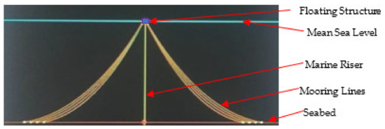
Figure 5. A labelled 3D hydrodynamic model of a semisubmersible platform showing the moorings and marine riser, designed in OrcaFlex 10.3d.
This entry is adapted from the peer-reviewed paper 10.3390/jmse10070973
This entry is offline, you can click here to edit this entry!