CubeSat Missions and Their Antenna Designs: History
Please note this is an old version of this entry, which may differ significantly from the current revision.
Contributor: , , , , , , , ,

CubeSats are a class of miniaturized satellites that have become increasingly popular in academia and among hobbyists due to their short development time and low fabrication cost. Their compact size, lightweight characteristics, and ability to form a swarm enables them to communicate directly with one another to inspire new ideas on space exploration, space-based measurements, and implementation of the latest technology. CubeSat missions require specific antenna designs in order to achieve optimal performance and ensure mission success. Over the past, a plethora of antenna designs have been proposed and implemented on CubeSat missions. Several challenges arise when designing CubeSat antennas such as gain, polarization, frequency selection, pointing accuracy, coverage, and deployment mechanisms.

  • antenna arrays
  • CubeSat missions
  • CubeSat antennas
  • Low Earth Orbit
  • Satellite communications

1. Introduction

CubeSats are a type of spacecraft called miniaturized satellites that are categorized based on their size, namely minisatellites, microsatellites, nanosatellites, picosatellites, and femtosatellites [1]. CubeSats belong to the class of nanosatellites having the smallest dimensions of 10 cm × 10 cm × 10 cm (1U) and a mass of 1.3 kg. As shown in Figure 1, other available sizes range from 2U up to 12U with a mass of 15.6 kg.
Figure 1. Different CubeSat standards.
Having such small and light features enables developers to provide a time- and cost-effective solution to designing fully functional satellites. The development cost is significantly less than standard satellite missions, as CubeSats can be launched as a secondary payload from standardized ejection modules such as the Poly-Picosatellite Orbital Deployer (P-POD) [2] or being deployed from the International Space Station [3]. The original reference of CubeSat design specifications dates back to 1999, when it was proposed by professors Jordi Puig-Suari from California Polytechnic State University and Bob Twiggs from Stanford University. These specifications, including mechanical, electrical, operational, and testing requirements, set the foundations for CubeSat design [4][5]. By referring to the maturing standards gradually developed over the years, a CubeSat mission can be finished within a few years.
The primary goal of introducing this new class of satellites was to educate graduate students on developing skills for designing, building, testing, and operating small satellites in low Earth orbit (LEO) and developing new scientific research methods, as well as advancing new space technologies. Meanwhile, the first CubeSat mission was launched in 2003, and only a handful of CubeSats were launched every year before 2013. As mentioned, this is because most CubeSats were developed by universities or research institutions. The number of CubeSat missions increased rapidly only when commercial applications joined the field [6]. To date, many CubeSats have been designed, launched, and operated successfully at low Earth orbit (LEO). Examples include CanX-1, CUTE-1, and AUU [7]. Very few CubeSats are designed, launched, and operated for deep space communications, such as those in [8][9]. On the other hand, CubeSats have limited functionality compared with other larger in size satellites. For instance, fitting an on-board propulsion system [10], large solar panels [11], radiators [12], as well as high-gain antennas [13] has proven to be a series of challenging tasks due to the limited room on the CubeSat [14]. However, the advancements in printed circuit board (PCB) technology [15][16] and the availability of off-the-shelf components (COTS) alongside the development of more powerful processors such as Field Programmable Gate Arrays (FPGAs) [17] have enabled researchers to develop cost-effective CubeSats for various challenging missions.

2. Background on CubeSats and Their Subsystems

Compared with conventional large and medium satellites, CubeSats weigh less and require less time for development (e.g., 1 year) [18]. Because of their limited size and weight, several restrictions should be considered in the design of a CubeSat system. The development of CubeSats has enabled the study and testing of novel ideas in the field of low-power microelectronics, digital signal processing, and communication protocols in space without spending millions of dollars.

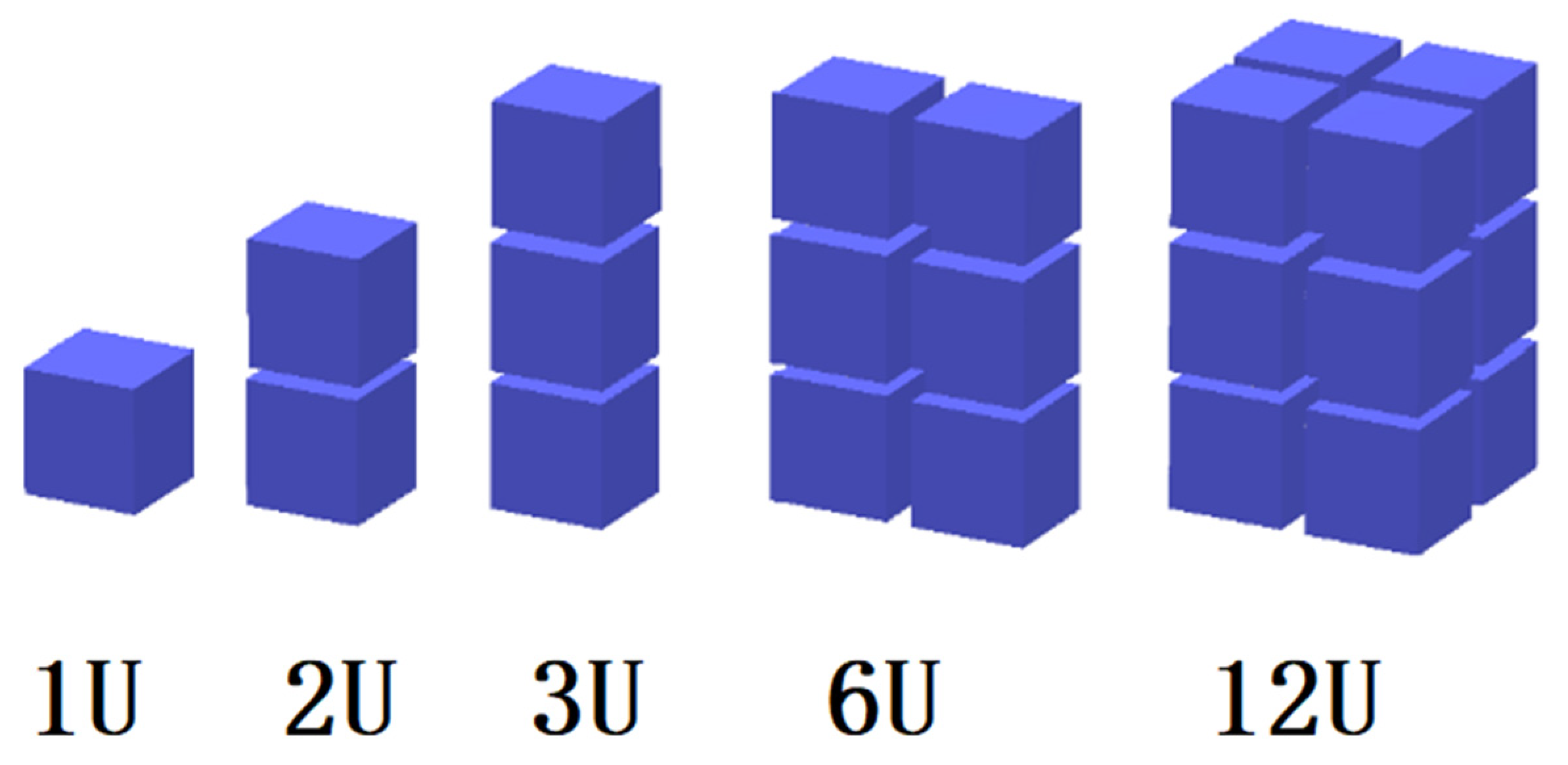
2.1. Mass and Volume

A small satellite often has limited room for the installation of electronics, antennas, payload, and solar panels. More specifically, large-volume antennas that generally have complex deployable systems are more likely to be excluded from a CubeSat mission. Thus, smaller antennas are preferable as they occupy small space on the CubeSat. Another important factor that influences the antenna’s choice and design for CubeSat missions is the mass. A typical CubeSat should weigh around 1.3 kg. Therefore, the weight of the antenna should be considered along with the different major weight contributions from the payloads, solar panels, core processors, batteries, and the chassis of the CubeSat. Failure to meet the CubeSat standards in terms of mass limitations would result in failure to launch.

2.2. Low Earth Orbit (LEO)

Most CubeSat missions take place on LEO, which ranges from about 150 km up to approximately 600 km and is below the ionosphere. Within this region, there are many science satellites and the International Space Station (ISS) [19]. When orbiting in LEO, a CubeSat undergoes different heat inputs and passes through different light ranges. The antenna might be designed to radiate certain amounts of power, but it should also be designed accordingly to reject any power received from unwanted sources. The noise temperature is a parameter which should be considered and modelled properly when designing an antenna for space missions where the thermal environment is harsh. For example, Earth can be considered an ideal blackbody in equilibrium that absorbs all the electromagnetic energy and emits energy at the same rate, which implies that Earth is an unwanted power source for the antenna. These fluctuations in the external space environment should be considered when designing a CubeSat.

2.3. Electrical Power Subsystem (EPS)

Another essential part for the satellite subsystems is the power subsystem, which constantly supplies the required power during the operation of the CubeSat. Power budgeting is one of the primary objectives of the CubeSat’s design, and it must follow accurate calculations and obey certain limitations. Solar power is the main source of CubeSat power, since sunlight is the only available energy source in space. Other extra energy sources such as fuel cells and radioactive decay units are not practical for CubeSats. The expected power usage of the CPU, the radio, and the sensors need to be predictable and tightly defined. An optimized scheme of power budgeting needs to be developed accordingly.
Many CubeSats use 5-V buses as their core components of the power system, as a 5-V microcontroller is common and popular. A voltage of 3.3 V is becoming increasingly popular for CubeSats as well. According to [20], the capacity of space-grade lithium polymer batteries in CubeSat applications can range from 1.1 Ah to 1.4 Ah among different suppliers. The researchers of [21] presented a design for a CubeSat bus that can provide 1.3 W of power to support some kinds of Earth observation missions and makes an allocation of the power budget to each subsystem.

2.4. Command and Data Handling Subsystem (C&DH)

The main processor subsystem, also known as Command and Data Handling (D&DH), coordinates complex actions taken by different parts within the system and provides stable and synchronized operation. The main processor of a CubeSat needs to be small and consume a low amount of power. Most current CubeSat missions use microcontrollers, but microprocessors are being considered for future missions. Some common processors such as ARMA, PC-104, and H8S-2674R have been chosen for some CubeSat missions [22][23][24]. Processors such as the PIC series and AT91SAM series are also available from providers, namely Pumpkin and Tyvak, and have also been applied in this kind of small satellite project. Additionally, applications of BasicX-24 and Arduino as the main processors of CubeSats are compared in [25]. FPGAs are also an attractive solution for CubeSat C&DHs as they offer in-obit reconfiguration, and their fabric can be designed to be tailored to specific mission requirements [16].

2.5. Propulsion Subsystem

CubeSats may use propulsion systems to realize active attitude control, reaction wheel desaturation, drag recovery, orbit changes and proximity operations [26]. In addition, a proper propulsion system can help a CubeSat slow down orbital decay and extend its lifetime. Because of the restrictions on CubeSats, their propulsion systems can only be used on specific occasions. The following technologies have been applied on current CubeSat missions: solar sail, cold gas, electric propulsion systems, and chemical propulsion systems [27]. The design of propulsion systems is still being developed to push the capabilities of CubeSats even further.

2.6. Attitude Determination and Control Subsystem (ADCS)

The ADCS for CubeSats is responsible for controlling the orientation of the spacecraft from the current attitude to a desired one. Various sensors or gyroscopes are used to record the orientation. For example, magnetic coils and reaction wheels are applied to provide necessary torques to reorient the satellite. Generally, two types of stabilization methods are utilized, namely spin stabilization and three-axis stabilization. Spin-stabilization requires one of the satellite axes to be fixed toward a specific direction, and then the body of the satellite is rotated accordingly. For this method, an initial force will be applied to the body of the satellite around an axis, and then the satellite will keep rotating because of the moment of inertia in space. Secondly, with three-axis stabilization, a satellite can be reoriented and stabilized in three different orthogonal axes instead of spinning around one axis, which results in maintaining a fixed attitude relationship with Earth or a successful inter-satellite link, respectively [28].

3. Single-Element CubeSat Antenna Designs

Single-element antennas vary from monopole and dipole antennas to planar, conical, and helical antennas, as well as guided wave structures like the bull’s eye antenna and metasurfaces. They are easier to construct than the antenna arrays but do not achieve such a high radiation performance compared with the antenna arrays. In 2001, monopole and dipole antennas were initially chosen and used for the communication subsystem of the CubeSat [29]

3.1. Monopole and Dipole Antennas

CubeSats operating at low frequencies such as VHF or UHF are equipped with wire antennas. In most cases, a wire antenna needs to be deployed after a CubeSat is launched into space. Deployment usually involves a composite tape spring [30][31][32]. In addition, wire antennas in dual-band operation can be used to transmit and receive data at the same time, similar to the 3 λ/4 dual band monopole antenna in [33]. Instead of simply employing the monopole antenna in the form of a straight wire, the researchers in [34] proposed a design for a monopole G-shaped antenna that is mounted on a CubeSat. It consists of two rectangular wire loops. The size of the antenna was smaller than the size of the CubeSat’s surface, so it could be mounted and stowed within the CubeSat body and did not need a deployment mechanism. Three structures were available based on three different frequencies of 150 MHz, 180 MHz, and 330 MHz. In [35], the researchers proposed four monopoles, which were combined to form a circular polarized isotropic antenna that established communication at the initial stages of CubeSat deployment. Similar to the monopole antenna, in many instances, the length of dipole antenna is a restriction for CubeSat missions to be solved. For example, in [30], a deployable dipole antenna using a curved, bi-stable composite tape spring was outlined. The dipole antenna operated at 250 MHz, and its total length was 55.88 cm, around five times larger than a CubeSat’s edge.
In some designs, monopole and dipole antennas can also be combined and used together to achieve the goals of a mission. In 2002, one of the first CubeSats, namely “XI-IV”, was launched and presented, where a 56-cm monopole antenna was used for the uplink at 144 MHz and placed vertical to a 35-cm (tip to tip) dipole antenna used for downlink communication (telemetry and beacon) at 430 MHz. Crucial health data were broadcasted constantly via a beacon signal at 430 MHz [29]. The researchers in [36] proposed a combined VHF/UHF (144/435 MHz) system. Both a dual-band dipole as well as a dual-band monopole were presented with the monopole configuration, acting as a fallback solution. An LC circuit was used as a notch filter in the UHF band to decide whether the dipole or monopole configuration was to be activated. Moreover, the researchers in [37] presented a communication system consisting of an S-band transmitter along with a UHF dipole as a backup transmitter. The downlink operated at 437 MHz and the uplink at 145 MHz, and these were implemented using a VHF monopole antenna. A dual-band folded-end dipole antenna was proposed in [38] for plastic CubeSats. The folded dipole does not require any deployment mechanism as it has a low profile and wraps around the CubeSat’s body. The dipole operates at 2.5 and 4.7 GHz and is fed by a microstrip line, which is placed inside the CubeSat’s body. The proposed antenna achieved one of the highest gains that could be found on wire antennas of 7.55 and 4.9 dBi at 4.7 and 2.5 GHz, respectively.

3.2. Planar Antennas

One of the main objectives of wireless communications and especially satellite communications is to use multiband or wideband low-profile antennas [39]. Patch antennas are good alternatives to wire antennas, as they have a low profile, do not require a deployment mechanism, are easy to fabricate, and have relatively low costs. Patch antennas are ideal for S-band communication, which is one of the international amateur satellite frequency ranges for high bit rates. They are characterized by higher gain than the wire antennas but suffer from narrow bandwidths. An interesting use of patch antennas can be found in [40]. A standard patch antenna was used as a feed for a parabolic reflector placed inside an inflatable volume. The patch antenna had dimensions of 9 cm × 9 cm, which complied with the CubeSat standards, and its gain was 8 dBi at 2.4 GHz. By adding the parabolic reflector, the antenna gain was increased to 16 dBi at 2.4 GHz. Researchers showed that a patch antenna can be used as a feed to a parabolic reflector instead of the traditional choice of a horn feed.
Another novel patch antenna design is proposed in [41], where an F-shaped patch antenna was under investigation. The results show that the patch antenna could achieve a gain of 8.5 dBi at 2.45 GHz. Furthermore, in [42] a dual-feed, L/S dual-band-stack patch antenna design is presented. This antenna operated in the L-band at 1.57 GHz for receiving the position signals from GPS satellites and in the S-band at 2.2 GHz for downlink transmission to the ground station. Even though the antenna consisted of 3 layers, it weighed less than 120 g and maintained a low profile of 11 mm, which conforms to the CubeSat standards. A Koch curve microstrip fractal antenna was presented which efficiently utilized the available space by maintaining a wide bandwidth [43]. The antenna was attached on a FR-4 substrate with dimensions of 3.5 cm × 4.5 cm and had an operating frequency range from 2.25 GHz to 2.45 GHz.

3.3. Antenna Integrated with Solar Panels

Solar panels represent the main source of power for a CubeSat, and thus it is important to reserve available space for their installation on the satellite’s body. On the other hand, the antenna is another subsystem of the CubeSat that requires instalment space and is also of great importance when it comes to mission success in terms of communication. Consequently, integrating antennas with solar panels was proven to be a very efficient approach to using a CubeSat’s available space while at the same time avoiding the requirement of a deployment mechanism [44]. An integrated solar panel-antenna system must keep the received solar energy loss to low levels. Four types of integration between solar panels and antennas are presented in [45]:
  • Place patch antennas under the solar cells;
  • Create slot antennas and deposit solar cells directly on top of them [44];
  • Place transparent antennas directly on top of solar cells [44];
  • Integrate transparent antennas on solar cells [46].
Thus, solar cells with patch antennas and slot antennas where the transparency is kept high are two possible solutions for space missions.

3.4. Conical Spiral Helix Antenna

Conical spiral and helix antennas can easily change from a 2D structure while stowed to a 3D structure during deployment. When compressing the conical spiral into a panel, it is possible to mount the antenna on one of the CubeSat’s surfaces. Once the CubeSat is launched into space, the conical spiral antenna can be easily released and flick up to its functional 3D shape. The challenges for this kind of antenna are usually related to feeding mechanisms. Designers need to avoid any impedance mismatch and provide a stable deployable mechanism. Furthermore, feeding from the top or bottom of the conical spiral shows different radiation performance. The maximum gain direction of this kind of antenna is from the smallest element to the biggest one. In [47], a deployable helical UHF antenna is presented. The antenna can be stowed in a 10 cm × 10 cm × 5 cm package, and when deployed, it can reach up to 137.16 cm in length and 35 cm in diameter. A 5-turn helix contributes to a gain of 10 dBi, while a 2-turn taper helps to improve the axial ratio to less than 2 dB. The conductive element of the antenna is made of copper adhesive tape. Another design that employs a similar deployment concept is described in [48].

3.5. Other Antenna Designs

As shown in Table 1, the “bull’s eye” antenna, as demonstrated in [49], has grooves in the shape of a bullseye. It is useful for inter-CubeSat communications, and it is possible to be employed and used for a CubeSat swarm. In addition, it also has a low profile and high gain. Another special design presented in [50] is that of a dual-band cylindrical dielectric resonator antenna (DRA). In general, a DRA presents some interesting features, such as a small size, wide bandwidth, high radiation efficiency, and low loss, making them a good alternative for CubeSat integration. The proposed DRA utilizes a microstrip line as a feed and a rotated plus-shaped slot placed on an FR4 epoxy sheet to excite the cylindrical dielectric resonator. The resonator has a height of 5 mm and a diameter of 10 mm. The modes of operation of the resonator determine the resonant frequency of the antenna, which in this case is at 7.7 GHz and at 11.4 GHz. The simulated and measured results of this design verify the feasibility of using DRAs for CubeSat missions. Researchers of [51] presented a novel S-band antenna design that provides good radiation performance and occupies a small area on a CubeSat. The antenna consists of 4 balanced inductive exciters (BIEs) placed at the top surface of a 1U CubeSat. The main idea is to transform the 1U CubeSat platform into an efficient radiator by employing characteristic mode analysis. The proposed antenna has the capability to steer the radiation beam at both principle planes as well as the capability of changing its polarization between CP and LP. Recently, metasurface antennas have been considered for deep space CubeSat missions [52]. More specifically, a metal-only modulated metasurface antenna excited by surface waves from a circular waveguide was proposed. The antenna operates at 32 GHz and achieves a gain of 24.4 dBi without needing a deployment mechanism.

3.6. Recommendation for Single-Element Antennas and CubeSat Missions

Most of the current existing CubeSats employed single-element antennas. Dipole, monopole, and patch antennas are widely chosen as they are easy to design and deploy. The deployment mechanisms of whip antennas have been successfully implemented on many CubeSat missions. It is recommended to operate whip antennas at a lower frequency band such as UHF or VHF, as their wide signal coverage enables tracking and telemetry on these bands. However, considering the lengths of whip antennas might be too long, a CubeSat mission can deploy multiple dipole or monopole antennas to avoid complex deployment issues. Whip antennas operating on frequencies higher than S-band will have lengths several times smaller than those operating at UHF and VHF. An interesting alternative is to utilize the CubeSat body as an efficient radiator, which may provide beam steering and polarization agility benefits. More challenging applications of CubeSats where the data rates are considerably higher than 9.6 kbps require the use of higher frequency bands, such as L-, S-, Ka-, or V-band. In these cases, more sophisticated antenna structures are needed, such as the metasurface or bull’s eye antenna.
The higher potential of single-element antennas is still being explored, and many new structures other than patch and whip antennas have been developed for several CubeSat missions. However, they all aim at optimizing the antenna characteristics within the available space and weight limitations. In other words, the design of single-element antennas becomes a task of balancing the antenna performance and the limitations imposed by the CubeSat standard. Thus, flexible materials for supporting the deployment mechanism need to be investigated for specific antenna designs. A typical example is a design of membrane antennas [53] that employs a foldable membrane plated with conductors.

This entry is adapted from the peer-reviewed paper 10.3390/electronics11132021

References

  1. Shimmin, R.; Agasid, E.; Burton, R.; Carlino, R.; Defouw, G.; Perez, A.; Karacaliglu, A.; Klamm, B.; Rademacher, A.; Schalkwyck, J. Small Spacecraft Technology State of the Art; NASA Mission Design Division Ames Research Center, Moffett Field: Santa Clara, CA, USA, 2015; Volume NASA/TP–2015–216648/REV.
  2. Puig-Suari, J.; Turner, C.; Ahlgren, W. Development of the standard CubeSat deployer and a CubeSat class PicoSatellite. In Proceedings of the 2001 IEEE Aerospace Conference Proceedings (Cat. No.01TH8542), Big Sky, MT, USA, 10–17 March 2001; Volume 1, pp. 347–353.
  3. Wuerl, A.; Wuerl, M. Lessons learned for deploying a microsatellite from the International Space Station. In Proceedings of the 2015 IEEE Aerospace Conference, Big Sky, MT, USA, 7–14 March 2015; pp. 1–12.
  4. Twiggs, B.; Puig-Suari, J. CUBESAT Design Specifications Document; Stanford University: Stanford, CA, USA; California Polytechnical Institute: San Luis Obispo, CA, USA, 2003.
  5. ESA. First P-Pod Integration. Available online: http://www.esa.int/spaceinimages/Images/2012/02/First_P-POD_integration2 (accessed on 30 December 2021).
  6. Swartwout, M. The first one hundred CubeSats: A statistical look. J. Small Satell. 2013, 2, 213–233.
  7. Klofas, B.; Anderson, J.; Leveque, K. A Survey of Cubesat Communication Systems. In Proceedings of the 5th Annual CubeSat Developers Workshop, San Luis Obispo, CA, USA, 9–11 April 2008.
  8. Chahat, N.; Decrossas, E.; Gonzalez-Ovejero, D.; Yurduseven, O.; Radway, M.J.; Hodges, R.E.; Estabrook, P.; Baker, J.D.; Bell, D.J.; Cwik, T.A.; et al. Advanced cubesat antennas for deep space and earth science missions: A review. IEEE Antennas Propag. Mag. 2019, 61, 37–46.
  9. Malphrus, B.K.; Freeman, A.; Staehle, R.; Klesh, A.T.; Walker, R. 4—Interplanetary CubeSat missions. In Cubesat Handbook; Cappelletti, C., Battistini, S., Malphrus, B.K., Eds.; Academic Press: Cambridge, MA, USA, 2021; pp. 85–121.
  10. Tummala, A.R.; Dutta, A. An overview of cube-satellite propulsion technologies and trends. Aerospace 2017, 4, 58.
  11. Santoni, F.; Piergentili, F.; Donati, S.; Perelli, M.; Negri, A.; Marino, M. An innovative deployable solar panel system for Cubesats. Acta Astronaut. 2014, 95, 210–217.
  12. Bunce, D.T.; Bassett, K.P.; Ghosh, A.R.; Barnett, P.R.; Haken, D.M.; Coverstone, V.L.; Yost, B.D.; Feller, J.R.; Agasid, E.F. Microvascular Composite Radiators for Small Spacecraft Thermal Management Systems. In Proceedings of the 30th Annual AIAA/USU Conference on Small Satellites, Logan, UT, USA, 6–11 August 2016.
  13. Gao, S.; Brenchley, M.; Unwin, M.; Underwood, C.I.; Clark, K.; Maynard, K.; Boland, L.; Sweeting, M.N. Antennas for small satellites. In Proceedings of the 2008 Loughborough Antennas and Propagation Conference, Loughborough, UK, 17–18 March 2008; pp. 66–69.
  14. Selva, D. A survey and assessment of the capabilities of Cubesats for Earth observation. Acta Astronaut. 2012, 74, 50–68.
  15. Schaffner, J. The Electronic System Design, Analysis, Integration, and Construction of the Cal Poly State University CP1 CubeSat. In Proceedings of the 16th Annual AIAA/USU Conference on Small Satellites, Logan, UT, USA, 12–15 August 2002.
  16. Theoharis, P.I.; Raad, R.; Tubbal, F.; Khan, M.U.A.; Liu, S. Software-Defined Radios for CubeSat Applications: A Brief Review and Methodology. IEEE J. Miniat. Air Space Syst. 2020, 2, 10–16.
  17. Olivieri, S.J.; Aarestad, J.; Pollard, L.H.; Wyglinski, A.M.; Kief, C.; Erwin, R.S. Modular FPGA-based software defined radio for CubeSats. In Proceedings of the 2012 IEEE International Conference on Communications (ICC), Ottawa, ON, Canada, 10–15 June 2012; pp. 3229–3233.
  18. Sweeting, M.N.; Underwood, C.I. Small Satellite Engineering and Applications. In Spacecraft Systems Engineering; John Wiley & Sons, Ltd.: Hoboken, NJ, USA, 2011; pp. 575–605.
  19. Wilson, J.; Cucinotta, F.; Golightly, M.; Nealy, J.; Qualls, G.; Badavi, F.; De Angelis, G.; Anderson, B.; Clowdsley, M.; Luetke, N.; et al. International space station: A testbed for experimental and computational dosimetry. Adv. Space Res. 2005, 37, 1656–1663.
  20. Navarathinam, N.; Lee, R.; Chesser, H. Characterization of Lithium-Polymer batteries for CubeSat applications. Acta Astronaut. 2011, 68, 1752–1760.
  21. Waydo, S. CubeSat design for LEO-based Earth science missions. In Proceedings of the IEEE Aerospace Conference, Big Sky, MT, USA, 9–16 March 2002; pp. 435–445.
  22. Wells, J.; Stras, L.; Jeans, T. Canada’s Smallest Satellite: The Canadian Advanced Nanospace Experiment (CanX-1). In Proceedings of the 16th Annual AIAA/USU Conference on Small Satellite, Logan, UT, USA, 12–15 August 2002.
  23. Schmidt, M.; Zeiger, F.; Schilling, K. Design and implementation of in-orbit experiments on the pico-satellite UWE-1. In Proceedings of the 57th International Astronautical Congress, IAC-06-E2, Valencia, Spain, 2–6 October 2006; Volume 1.
  24. Long, M.; Lorenz, A.; Rodgers, G.; Tapio, E.; Tran, G.; Jackson, K.; Twiggs, R.; Bleier, T.; Solutions, S. A cubesat derived design for a unique academic research mission in earthquake signature detection. In Proceedings of the 16th Annual AIAA/USU Conference on Small Satellite, Logan, UT, USA, 12–15 August 2002.
  25. Antunes, S. DIY Satellite Platforms: Building a Space-Ready General Base Picosatellite for Any Mission; O’Reilly Media, Inc.: Sebastopol, CA, USA, 2012.
  26. Lemmer, K. Propulsion for CubeSats. Acta Astronaut. 2017, 134, 231–243.
  27. Mueller, J.; Hofer, R.; Ziemer, J. Survey of Propulsion Technologies Applicable to Cubesats; Jet Propulsion Laboratory, National Aeronautics and Space Administration: Pasadena, CA, USA, 2010.
  28. Falbel, G.; Puig-Suari, J.; Peczalski, A. Sun oriented and powered, 3 axis and spin stabilized CubeSats. In Proceedings of the IEEE Aerospace Conference, Big Sky, MT, USA, 9–16 March 2002; Volume 1, pp. 447–455.
  29. Tsuda, Y.; Sako, N.; Eishima, T.; Ito, T.; Arikawa, Y.; Miyamura, N.; Tanaka, A.; Nakasuka, S. University of Tokyo’s CubeSat Project-Its Educational and Technological Significance. In Proceedings of the 15th Annual AIAA/USU Conference on Small Satellites, Logan, UT, USA, 13–16 August 2001.
  30. Costantine, J.; Tawk, Y.; Christodoulou, C.G.; Banik, J.; Lane, S. CubeSat Deployable Antenna Using Bistable Composite Tape-Springs. IEEE Antennas Wirel. Propag. Lett. 2012, 11, 285–288.
  31. Murphey, T.; Jeon, S.; Biskner, A.; Sanford, G. Deployable Booms and Antennas Using Bi-Stable Tape-Springs. In Proceedings of the 24th Annual AIAA/USU Conference on Small Satellite, Logan, UT, USA, 9–12 August 2010.
  32. Murphey, T.W.; Sanford, G.E.; Jeon, S. Deployable Space Boom Using Bi-Stable Tape Spring Mechanism. U.S. Patent No. 8,770,522 B1, 8 July 2014.
  33. Leao, T.F.C.; Mooney-Chopin, V.; Trueman, C.W.; Gleason, S. Design and Implementation of a Diplexer and a Dual-Band VHF/UHF Antenna for Nanosatellites. IEEE Antennas Wirel. Propag. Lett. 2013, 12, 1098–1101.
  34. Yousuf, H.J.; Haider, M.M.; Siddique, M.K.; Amin, M. Analysis of G-shape antennas mounted on a CUBESAT. In Proceedings of the 2008 2nd International Conference on Advances in Space Technologies, Islamabad, Pakistan, 29–30 November 2008; pp. 28–32.
  35. Tatomirescu, A.; Pedersen, G.F.; Christiansen, J.; Gerhardt, D. Antenna system for nano-satelite mission GOMX-3. In Proceedings of the 2016 IEEE-APS Topical Conference on Antennas and Propagation in Wireless Communications (APWC), Cairns, QLD, Australia, 19–23 September 2016; pp. 282–285.
  36. Schraml, K.; Narbudowicz, A.; Chalermwisutkul, S.; Heberling, D.; Ammann, M.J. Easy-to-deploy LC-loaded dipole and monopole antennas for cubesat. In Proceedings of the 2017 11th European Conference on Antennas and Propagation (EUCAP), Paris, France, 19–24 March 2017; pp. 2303–2306.
  37. Wilke, R.; Reiffenrath, M.; Parow-Souchon, K.; Heberling, D. S-Band, UHF and VHF Communication System for Cubesats including Ground Station Software. In Proceedings of the 8th Pico- and Nanosatellite Workshop, Würzburg, Germany, 15–16 September 2015.
  38. Liu, S.; Raad, R.; Theoharis, P.I.; Tubbal, F. Dual-Band Folded-End Dipole Antenna for Plastic CubeSats. IEEE J. Miniat. Air Space Syst. 2020, 1, 172–178.
  39. Balanis, C.A. Antenna Theory: Analysis and Design; John Wiley & Sons: Hoboken, NJ, USA, 2016.
  40. Babuscia, A.; Corbin, B.; Knapp, M.; Jensen-Clem, R.; van de Loo, M.; Seager, S. Inflatable antenna for cubesats: Motivation for development and antenna design. Acta Astronaut. 2013, 91, 322–332.
  41. Tubbal, F.E.; Raad, R.; Chin, K.W. A wideband F-shaped patch antenna for S-band CubeSats communications. In Proceedings of the 2016 10th International Conference on Signal Processing and Communication Systems (ICSPCS), Surfers Paradise, QLD, Australia, 19–21 December 2016; pp. 1–4.
  42. Yao, Y.; Liao, S.; Wang, J.; Xue, K.; Balfour, E.A.; Luo, Y. A New Patch Antenna Designed for CubeSat: Dual feed, L/S dual-band stacked, and circularly polarized. IEEE Antennas Propag. Mag. 2016, 58, 16–21.
  43. Palacios, O.F.G.; Vargas, R.E.D.; Perez, J.A.H.; Erazo, S.B.C. S-band koch snowflake fractal antenna for cubesats. In Proceedings of the 2016 IEEE ANDESCON, Arequipa, Peru, 19–21 October 2016; pp. 1–4.
  44. Yekan, T.; Baktur, R. Conformal Integrated Solar Panel Antennas: Two effective integration methods of antennas with solar cells. IEEE Antennas Propag. Mag. 2017, 59, 69–78.
  45. Mahmoud, M.N. Integrated Solar Panel Antennas for Cube Satellites; Utah State University: Logan, UT, USA, 2010.
  46. Lim, E.H.; Leung, K.W. Transparent Dielectric Resonator Antennas for Optical Applications. IEEE Trans. Antennas Propag. 2010, 58, 1054–1059.
  47. Ochoa, D.; Hummer, K.; Ciffone, M. Deployable Helical Antenna for nano-Satellites. In Proceedings of the 28th Annual AIAA/USU Conference on Small Satellites, Logan, UT, USA, 2–7 August 2014.
  48. Muri, P.; Challa, O.; McNair, J. Enhancing small satellite communication through effective antenna system design. In Proceedings of the Milcom 2010 Militar Communications Conference, San Jose, CA, USA, 31 October–3 November 2010; pp. 347–352.
  49. Vourch, C.J.; Drysdale, T.D. V-Band Bull’s Eye Antenna for CubeSat Applications. IEEE Antennas Wirel. Propag. Lett. 2014, 13, 1092–1095.
  50. Borthakur, M.; Khan, T.; Dash, S.K.K. Circularly polarized dual-band cylindrical dielectric resonator antenna for Cubesat applications. In Proceedings of the 2017 XXXIInd General Assembly and Scientific Symposium of the International Union of Radio Science (URSI GASS), Montreal, QC, Canada, 19–26 August 2017; pp. 1–4.
  51. Dicandia, F.A.; Genovesi, S. A compact CubeSat antenna with beamsteering capability and polarization agility: Characteristic modes theory for breakthrough antenna design. IEEE Antennas Propag. Mag. 2020, 62, 82–93.
  52. González-Ovejero, D.; Chahat, N.; Sauleau, R.; Chattopadhyay, G.; Maci, S.; Ettorre, M. Additive Manufactured Metal-Only Modulated Metasurface Antennas. IEEE Trans. Antennas Propag. 2018, 66, 6106–6114.
  53. Warren, P.A.; Steinbeck, J.W.; Minelli, R.J.; Muller, C. Large, deployable S-band antenna for 6U CubeSat. In Proceedings of the 29th Annual AIAA/USU Conference on Small Satellites, Logan, UT, USA, 8–13 August 2015.
More
This entry is offline, you can click here to edit this entry!