Your browser does not fully support modern features. Please upgrade for a smoother experience.
Please note this is an old version of this entry, which may differ significantly from the current revision.
Demanding materials like hardened steel confront issues during machining owing to their poor heat conductivity, resulting in focalized high temperatures. This issue has a substantial impact on tool life because it causes an elevated incidence of tool wear, which lowers machining quality and yield. The chemical interaction of difficult-to-cut materials with tool materials culminates in tool failure that is sudden and unexpected, as well as a poor surface finish.
- hard turning
- self-propelled rotary tools
- flank wear
- genetic programming
1. Introduction
Various strategies were used in the previous research to diffuse the accumulated heat. Coolant (or lubricants) have, for example, been frequently utilized to disperse and lessen the influence of induced heat, allowing the cutting domain temperature to be maintained inside a tolerable range [1][2][3][4]. The oils and liquids applied in the machining region function as a lubricant, reducing the degree of engagement amongst the chip and the tool and forming a thin layer [5]. The benefits of machining with coolant/lubricant are evident, but the usage of a coolant/lubricant has major consequences for humans and the environment [6]. Researchers have explored machining materials without using cutting fluids, often known as dry machining, to avoid deleterious cutting fluids during machining processes [7]. The most prevalent machining processes for difficult-to-cut materials have been hard turning and grinding [8]. As reported in [9], grinding has poor throughput and restricted capabilities in terms of flexibility and machined geometries. Turning difficult-to-cut machine materials instead of grinding, on the other hand, produces a high-quality machined surface at a lower cost [10]. The adoption of turning instead of grinding and without cutting fluids for hardened steel and other hard-to-machine materials has attracted industrial interest in recent years [11].
Dry hard turning lowers processing time and specific cutting energy consumption, as well as the healthcare and ecological problems associated with typical coolant-based machining processes [12]. Hard turning, on the other hand, has been impeded by significant tool wear [13][14]. As a result, regulating tool wear and its impact on the consistency of the workpiece surface has been a substantial technical dilemma.
2. Self-Propelled Rotary Carbide Tool
Hard turning necessitates tool materials featuring adequate wear and temperature resilience due to the tremendous specific forces and temperatures in the narrow interface zone across the tool and the machining surface. Furthermore, as established in [15], the indentation hardness of the tool must be thrice that of the machining surface. Ceramics and cubic boron nitride (cBN) tools are typically considered for hard turning since tool wear and plastic deformation of the cutting edge degrade the quality and consistency of the machining surfaces [16][17][18]. Many researchers have investigated the chip removal and wear mechanisms of hard turning employing cBN, polycrystalline cubic boron nitride (PcBN), and ceramic cutting tools. Sobiyi, et al. [19] explored the deterioration of ceramic and PcBN cutting tools during machining AISI 440B stainless steel under various machining settings. The cutting speed seemed to have the greatest impact upon the flank wear rate in the experiments, and it surged as the cutting speed grew for two cutting tools. With mixed ceramic tools, flank wear increased as feed increased, but with cBN cutting tools, the converse was truly attributable to severe tool vibration. The cBN tool also had a greater metal removal rate because of its rigidity and tendency to sustain its toughness at greater cutting speeds and feed rates. The primary wear mode for ceramic cutting tools was abrasive wear, while the primary wear modes for cBN tools were adhesive wear and abrasive wear. At reduced machining rates, both tools generated long, continuous, serrated cutting chips, but when the cutting speed rose over 150 m/min, the cutting chips become serrated and segmented. When turning hardened steel beyond 50 HRC, there was a propensity for increased tool wear intensity and exacerbated abrasion and diffusion wear processes, as documented [20]. It has also been reported that raising the hardness of the workpiece to 50 HRC reduced surface roughness, but raising the hardness of the workpiece between 50 to 65 HRC enhanced surface roughness [21]. The result of expanding workpiece hardness was thermal softening, substantial material lateral flows around the feed markings, and a compressing action on the tool flank face and the workpiece surface [22]. Tang, et al. [23] found that when the workpiece’s hardness level increased, so did the cutting forces. Tang, et al. [24] also studied the wear profiles and mechanics of PcBN tools in dry hard machining of AISI D2 hardened steel at varied hardness grades (40–60 HRC). The findings revealed that the hardness of the workpiece had a significant impact on flank wear. The primary wear modes in the flank wear of PcBN tools comprised abrasive wear in instances of 40–55 HRC, plus abrasive and delamination wear in scenarios of 60 HRC because of a sudden rise in resistance at tool-workpiece junctions, whereas the crater was the predominant wear in the rake surface of PcBN tools. One of the most important aspects of dry machining is the selection of the right cutting tool and its material [25]. The use of traditional tools and materials raises the cutting temperature in the cutting zone, resulting in rapid tool wear, which compromises the dimensional precision, surface roughness, and tool life of the workpiece. Carbides, for example, are not typically utilized for hard turning; instead, they are employed at low speeds for regular turning operations to maximize tool life [26]. In the same way, when doing hard machining, a single cutting point tool with only one main cutting edge has drawbacks. It has the downside of a rapid rate of wear and a high temperature at the cutting tool’s tip, which causes the tool to break prematurely. During machining, the tool is constantly in physical contact with the work material, causing a rapid rise in tool temperature, which accelerates tool wear and causes thermal damage to the machined surface. Furthermore, high-temperature fluctuations often plastically distort the tooltip, resulting in poor cutting accuracy. In the case of a single-point cutting tool, the material removal rate (MRR) is generally quite low. The ability of rotary cutting tools, as well as the properties of advanced cutting tool materials such as cBN, PcBN, and ceramic, to keep a viable cutting edge at high temperatures, has rendered them the most preferred alternative for machining hardened materials.
Rotary tools provide a cost-effective option to the conundrum of severe heat accumulation as well as maintain good tool performance during machining challenging materials in dry settings [27]. For example, Kishawy, et al. suggested in [11][28], that rotary tools significantly extended tool life, reduced cutting temperature, and enhanced MRR. Ezugwu [29] corroborated that which was described in [11][28], and maintained that rotary tools provided even surfaces, especially in the event of difficult-to-cut materials. As a result of its superior performance for difficult-to-machine materials, rotary tools have attracted a lot of attention from the machining community.
A rotary cutting tool is a disk-shaped cutting tool that revolves around its axis, as shown in Figure 1. In industry and research, two types of rotary tools are commonly used: driven and self-propelled. The insert’s rotating motion is generated by an independent source for the actively driven rotary tool (ADRT), whereas the chip progression across the tool rake surface forces the insert to revolve for self-propelled rotary tools (SPRT) [11]. Because the tool rotates, each segment of the cutting tip is involved in cutting over a minimal length of time, enabling every portion of the cutting surface to cool down after contact. When contrasted to standard tools, this results in intrinsically excellent cooling capabilities, allowing for the employment of cost-effective carbide inserts while hard turning. Exceptional wear tolerance and extended tool life have also been reported in earlier investigations, thus emphasizing rotary tools for hard machining. Ahmed, et al. [30] studied and evaluated the SPRT’s functionality in the dry machining of hardened steel alloy. The results confirmed that the SPRT provided smaller cutting forces, fairly low flank tool wear and extremely low machining temperature than conventional tools. When machining with SPRT, flank tool wear was curbed by 22 and 37% in the finest and harshest cutting circumstances, respectively. Similarly, when the cutting tool temperature was at its highest, it was discovered that the temperature was lowered by roughly 13%. Furthermore, when the tool temperature was at its lowest, the tool temperature was reduced by roughly 37%. As opposed to traditional tools, the use of SPRT can result in a significant decrease in power usage and a 20 times increase in tool life [31][32]. Dessoly, et al. [27] also noticed that a rotating tool had a 50 °C lower cutting temperature than a fixed tool. A hybrid model was demonstrated in [33] to precisely replicate and study the machining process using SPRT. An average cutting temperature drop of 65 °C was observed between the customary and rotating tools. In the case of the rotary tool, the highest temperature was found in the chip’s core and did not spread to the secondary shear zone. The maximal temperature in addition to the tool bulk temperature reduced as the tool rotational speed increased, but the temperature rose afterward above 900 rpm rotational speed. Umer, et al. [34] proposed a model for evaluating SPRT performance during hardened steel machining. A finite element (FE) model was conceived to analyze the hard turning of AISI 51200 and estimate cutting forces with greater precision and accuracy. The tool-chip engagement span for the rotary tool case was recorded as shorter because of the differences in chip flow angles. Temperatures were greater in the fixed tool, and the rotating tool’s surface temperature was assessed to be around 35% lower than that of the fixed tools. Kishawy and Wilcox [35] investigated the efficacy of rotary tools while hard turning AISI 4340 steel with a hardness of 54–56 HRC. In both fixed and rotating scenarios, the effectiveness of carbide and TiN coated carbide inserts were examined. When rotary tools were assessed against fixed tools at the identical cutting settings, there was no indication of crater wear, and they demonstrated significant tool flank wear endurance. Subsequently, Kishawy, et al. [28] investigated the efficacy of SPRT and the consistency of workpiece surfaces when processing waspaloy and titanium alloys. In rotary tools, equally disseminated flank wear was noticed to be the primary cause of tool collapse, whereas in regular non-rotary tools, crater wear was discovered to be the leading trend. The cutting edge’s rotating movement was responsible for this. Because the cutting edge is continuously replenished by rotation, thermally stimulated degradation was less of a concern than the insert’s morphological viability.
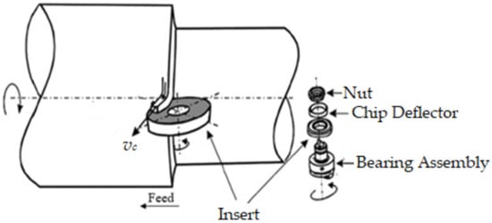
Figure 1. Characteristic rotary tool machining [11].
A variety of models have been presented to approximate the tool flank wear rate during machining. Li, et al. [36], for example, devised a theoretical model that encompasses both abrasive and adhesive wear in order to explore the mechanism of flank wear for tools constructed of various polycrystalline diamond (PCD) materials. The width of flank wear was estimated by computing the differential equation established to represent the rate of flank wear and its interaction with cutting parameters, tool characteristics, and the workpiece material. Choudhury, et al. [37] developed a tool wear model that quantitatively described the progression of tool wear in turning operations using parameters such as the index of diffusion, wear coefficient, and tool/workpiece hardness ratio. A prediction model was implemented in a work by Xiaoliang, et al. [38] to evaluate the depth of plastic deformation at various tool flank wear states. Bombiński, et al. [39] also designed a method for quickly diagnosing gradual tool wear (GTW) and catastrophic tool failure (CTF). This approach depended on analyzing the waveforms of the cutting force sensor signal in sequential time periods. Cutting forces increased when the flank wear area increased according to a study by Sikdar and Chen [40]. They constructed a mathematical model for a deeper insight into the correlation between flank wear region and cutting forces. Additionally, the mathematical model in [41] can be exploited to assess tool wear in a turning operation in real-time. The relation involving flank wear and the ratio of force components were derived for this purpose using data from several tests. FE models have also been used to investigate the wear mechanism in the machining of hard-to-cut materials in addition to analytical or mathematical models [42][43][44][45][46].
In the literature, SPRT has been demonstrated to be a very good alternative to hazardous cooling fluids and other techniques for minimizing extreme heat generation and preserving optimum tool operation. It does, in fact, offer a number of benefits, including superior cooling capabilities, less heat generation, increased tool life, improved MRR, lower cutting forces, higher wear tolerance, reduced power consumption, etc. When compared to ADRT, SPRT is a more cost-effective and feasible option for cutting difficult-to-machine materials. Although ADRT can provide more control, it requires an additional power supply, making it complicated and costly. A multitude of research has been published in the literature focusing on the wear mechanism for turning operations using typical single-point cutting tools. Likewise, a lot of analytical and FE models have been established to comprehend the wear mechanism in single-point cutting tools.
This entry is adapted from the peer-reviewed paper 10.3390/ma15124059
References
- Courbon, C.; Sajn, V.; Kramar, D.; Rech, J.; Kosel, F.; Kopac, J. Investigation of machining performance in high pressure jet assisted turning of Inconel 718: A numerical model. J. Mater. Process. Technol. 2011, 211, 1834–1851.
- Mia, M.; Dhar, N.R. Effect of high pressure coolant jet on cutting temperature, tool wear and surface finish in turning hardened (Hrc 48) steel. J. Mech. Eng. 2015, 45, 1–6.
- Al Bashir, M.; Mia, M.; Dhar, N.R. Investigations on Surface Milling of Hardened AISI 4140 Steel with Pulse Jet MQL Applicator. J. Inst. Eng. Ser. C 2018, 99, 301–314.
- dos Santos, F.A.; de Pinto, M.A.C.; dos Santos, R.O.B.; Bimestre, T.A.; Gama, R.P. Comparative analysis of the application of lubricant coolant by the MQF technique in the face milling machining process of hardened D2 steel alloy. Braz. J. Dev. 2021, 7, 10349–10370.
- Krolczyk, G.M.; Maruda, R.W.; Krolczyk, J.B.; Wojciechowski, S.; Mia, M.; Nieslony, P.; Budzik, G. Ecological trends in machining as a key factor in sustainable production—A review. J. Clean. Prod. 2019, 218, 601–615.
- Mia, M.; Dhar, N.R. Effects of duplex jets high-pressure coolant on machining temperature and machinability of Ti-6Al-4V superalloy. J. Mater. Process. Technol. 2018, 252, 688–696.
- Goindi, G.S.; Sarkar, P. Dry machining: A step towards sustainable machining—Challenges and future directions. J. Clean. Prod. 2017, 165, 1557–1571.
- Abbas, A.T.; El Rayes, M.M.; Luqman, M.; Naeim, N.; Hegab, H.; Elkaseer, A. On the Assessment of Surface Quality and Productivity Aspects in Precision Hard Turning of AISI 4340 Steel Alloy: Relative Performance of Wiper vs. Conventional Inserts. Materials 2020, 13, 2036.
- Astakhov, V.P. Machining of Hard Materials–Definitions and Industrial Applications. In Machining of Hard Materials; Davim, J.P., Ed.; Springer: London, UK, 2011; pp. 1–32. ISBN 978-1-84996-450-0.
- Afteni, M.; Terecoasa, I.; Afteni, C.; Paunoiu, V. Study on Hard Turning Process Versus Grinding in Manufacturing Some Bearing Inner Rings. In Proceedings of the 5th International Conference on Advanced Manufacturing Engineering and Technologies, Online, 23 April 2017; Majstorovic, V., Jakovljevic, Z., Eds.; Springer International Publishing: Cham, Switzerland, 2017; pp. 95–111.
- Kishawy, H.A.; Pang, L.; Balazinski, M. Modeling of tool wear during hard turning with self-propelled rotary tools. Int. J. Mech. Sci. 2011, 53, 1015–1021.
- Samantaraya, D.; Lakade, S. Hard Turning Cutting Tool Materials used in Automotive and Bearing Manufacturing Applications–A review. IOP Conf. Ser. Mater. Sci. Eng. 2020, 814, 012005.
- Zhao, J.; Liu, Z. Influences of coating thickness on cutting temperature for dry hard turning Inconel 718 with PVD TiAlN coated carbide tools in initial tool wear stage. J. Manuf. Process. 2020, 56, 1155–1165.
- Şap, E.; Usca, U.A.; Gupta, M.K.; Kuntoğlu, M. Tool wear and machinability investigations in dry turning of Cu/Mo-SiCp hybrid composites. Int. J. Adv. Manuf. Technol. 2021, 114, 379–396.
- Nakayama, K.; Arai, M.; Kanda, T. Machining Characteristics of Hard Materials. CIRP Ann. 1988, 37, 89–92.
- Karthik, M.S.; Raju, V.R.; Reddy, K.N.; Balashanmugam, N.; Sankar, M.R. Cutting parameters optimization for surface roughness during dry hard turning of EN 31 bearing steel using CBN insert. Mater. Today Proc. 2020, 26, 1119–1125.
- Seleznev, A.; Pinargote, N.W.S.; Smirnov, A. Machinability of Nickel-Based Superalloys Using Ceramic Tools. Automot. Eng. 2021.
- Bag, R.; Panda, A.; Sahoo, A.K.; Kumar, R. Cutting tools characteristics and coating depositions for hard part turning of AISI 4340 martensitic steel: A review study. Mater. Today Proc. 2020, 26, 2073–2078.
- Sobiyi, K.; Sigalas, I.; Akdogan, G.; Turan, Y. Performance of mixed ceramics and CBN tools during hard turning of martensitic stainless steel. Int. J. Adv. Manuf. Technol. 2015, 77, 861–871.
- Boing, D.; Schroeter, R.B.; de Oliveira, A.J. Three-dimensional wear parameters and wear mechanisms in turning hardened steels with PCBN tools. Wear 2018, 398–399, 69–78.
- Heydari, B.; Mahdi, M.A.; Reza, K.Z.H. The Effect of Workpiece Hardness and Cutting Parameters on Surface Roughness in Dry Hard Turning of X210Cr12 Cold Tool Steel. Modares Mech. Eng. 2017, 17, 241–247.
- Tang, L.; Gao, C.; Huang, J.; Shen, H.; Lin, X. Experimental investigation of surface integrity in finish dry hard turning of hardened tool steel at different hardness levels. Int. J. Adv. Manuf. Technol. 2015, 77, 1655–1669.
- Tang, L.; Cheng, Z.; Huang, J.; Gao, C.; Chang, W. Empirical models for cutting forces in finish dry hard turning of hardened tool steel at different hardness levels. Int. J. Adv. Manuf. Technol. 2015, 76, 691–703.
- Tang, L.; Sun, Y.; Li, B.; Shen, J.; Meng, G. Wear performance and mechanisms of PCBN tool in dry hard turning of AISI D2 hardened steel. Tribol. Int. 2019, 132, 228–236.
- Shihab, S.K.; Khan, Z.A.; Mohammad, A.; Siddiquee, A.N. A review of turning of hard steels used in bearing and automotive applications. Prod. Manuf. Res. 2014, 2, 24–49.
- Olgun, U.; Budak, E. Machining of Difficult-to-Cut-Alloys Using Rotary Turning Tools. Procedia CIRP 2013, 8, 81–87.
- Dessoly, V.; Melkote, S.; Lescalier, C. Modeling and verification of cutting tool temperatures in rotary tool turning of hardened steel. Int. J. Mach. Tools Manuf. 2004, 44, 1463–1470.
- Kishawy, H.A.; Becze, C.E.; McIntosh, D.G. Tool performance and attainable surface quality during the machining of aerospace alloys using self-propelled rotary tools. J. Mater. Process. Technol. 2004, 152, 266–271.
- Ezugwu, E.O. Improvements in the machining of aero-engine alloys using self-propelled rotary tooling technique. J. Mater. Process. Technol. 2007, 185, 60–71.
- Ahmed, W.; Hegab, H.; Mohany, A.; Kishawy, H. On machining hardened steel AISI 4140 with self-propelled rotary tools: Experimental investigation and analysis. Int. J. Adv. Manuf. Technol. 2021, 133, 3163–3176.
- Da Silva, R.H.L.; Hassui, A. Cutting force and surface roughness depend on the tool path used in side milling: An experimental investigation. Int. J. Adv. Manuf. Technol. 2018, 96, 1445–1455.
- Chen, P.; Hoshi, T. High-Performance Machining of SiC Whisker-Reinforced Aluminium Composite by Self-Propelled Rotary Tools. CIRP Ann. 1992, 41, 59–62.
- Ahmed, W.; Hegab, H.; Kishawy, H.A.; Mohany, A. Estimation of temperature in machining with self-propelled rotary tools using finite element method. J. Manuf. Process. 2021, 61, 100–110.
- Umer, U.; Kishawy, H.; Abidi, M.H.; Mian, S.H.; Moiduddin, K. Evaluation of Self-Propelled Rotary Tool in the Machining of Hardened Steel Using Finite Element Models. Materials 2020, 13, 5092.
- Kishawy, H.A.; Wilcox, J. Tool wear and chip formation during hard turning with self-propelled rotary tools. Int. J. Mach. Tools Manuf. 2003, 43, 433–439.
- Li, G.; Li, N.; Wen, C.; Ding, S. Investigation and modeling of flank wear process of different PCD tools in cutting titanium alloy Ti6Al4V. Int. J. Adv. Manuf. Technol. 2018, 95, 719–733.
- Choudhury, S.K.; Srinivas, P. Tool wear prediction in turning. J. Mater. Process. Technol. 2004, 153–154, 276–280.
- Liang, X.; Liu, Z.; Wang, B.; Hou, X. Modeling of plastic deformation induced by thermo-mechanical stresses considering tool flank wear in high-speed machining Ti-6Al-4V. Int. J. Mech. Sci. 2018, 140, 1–12.
- Bombiński, S.; Kossakowska, J.; Jemielniak, K. Detection of accelerated tool wear in turning. Mech. Syst. Signal Process. 2022, 162, 108021.
- Sikdar, S.K.; Chen, M. Relationship between Tool Flank Wear Area and Component Forces in Single Point Turning. J. Mater. Process. Technol. 2002, 128, 210–215.
- Choudhury, S.; Kishore, K. Tool wear measurement in turning using force ratio. Int. J. Mach. Tools Manuf. 2000, 40, 899–909.
- Tooptong, S.; Park, K.-H.; Kwon, P. A comparative investigation on flank wear when turning three cast irons. Tribol. Int. 2018, 120, 127–139.
- Nooraie, R.Y.; Safari, M.; Pak, A. Tool wear estimation in machining based on the flank wear inclination angle changes using the FE method. Mach. Sci. Technol. 2020, 24, 425–445.
- Equeter, L.; Ducobu, F.; Rivière-Lorphèvre, E.; Abouridouane, M.; Klocke, F.; Dehombreux, P. Estimation of the influence of tool wear on force signals: A finite element approach in AISI 1045 orthogonal cutting. AIP Conf. Proc. 2018, 1960, 070012.
- Jiang, L.; Wang, D. Finite-element-analysis of the effect of different wiper tool edge geometries during the hard turning of AISI 4340 steel. Simul. Model. Pract. Theory 2019, 94, 250–263.
- Liu, C.; Zhang, Z.; Yang, G.; Zhou, A.; Wang, G.; Qin, S.; Wang, A.; Wang, W.; Zhang, X. Finite element analysis and wear mechanism of B4C–TiB2 ceramic tools in turning AISI 4340 workpieces. Ceram. Int. 2021, 48, 5459–5467.
This entry is offline, you can click here to edit this entry!