Due to the excessive consumption of fossil fuels and the growing problem of climate change caused by environmental pollution, renewable energy research and development, such as solar, wind, and tidal energy, has attracted worldwide attention [
1,
2,
3,
4]. However, renewable energy power generation is often intermittent and unpredictable, which requires large-scale energy storage systems to effectively buffer such fluctuations to achieve stable energy output for smart grid [
5,
6,
7]. As an efficient and flexible energy storage device, lithium-ion batteries (LIBs) have not only been successfully applied in electronic consumer products such as cellphones and laptops, but are also expanding their range to electric vehicles and other fields [
8,
9,
10,
11]. However, the high production cost, limited lithium resource reserves, and the use of toxic and flammable organic electrolytes make lithium-ion batteries expensive, hazardous, and environmentally polluting, strongly impeding their further development and application in grid-scale energy storage [
12,
13,
14]. Therefore, researchers are seeking new energy storage battery systems to replace LIBs in terms of cost, safety, and sustainability.
Among those energy storage devices, aqueous electrolytes have been widely employed in secondary battery systems for Na, K, Mg
++2+, Al
3+, Ca
2+, Zn
2+, etc. in recent years because of their safety, high ionic conductivity, and ease of operation [
15,
16]. Among aqueous multivalent ion batteries, ZIBs stand out due to the following characteristics: (1) Zn metal reserves are abundant and the manufacture process of ZIBs occurs in an air environment, making it cost-effective; (2) Zn metal anode has a low redox potential of −0.76 V with respect to a standard hydrogen electrode and high theoretical gravimetric/volumetric capacity (820 mAh·g
−1/5855 mAh·cm
−3); (3) Zn metal can be directly applied as an anode due to its excellent electrochemical stability and reversibility in water; (4) ZIBs are highly safe because of the application of nontoxic aqueous electrolyte [
17,
18]. However, considering the large ionic radius of hydrated zinc (5.5 Å vs. 0.74 Å for Zn ion), the intercalation of hydrated zinc ions would either require large spacing to accommodate the large ions or withstand a large desolvation penalty for smaller dehydrated ions to intercalate, imposing a great challenge in the development of suitable cathode materials [
19]. At present, manganese-based oxides, vanadium-based oxides, and Prussian blue analogs are mainly developed as cathode materials for ZIBs [
20]. Among them, manganese-based oxides are widely recognized as candidates for the commercialization of ZIBs because of their mature synthesis process, abundant resources, lack of pollution, high specific capacity, and high operating voltage [
21]. However, the further application of Mn-based cathodes is hindered by two major issues. The redox reaction involving Mn
4+ is usually accompanied by the Jahn–Teller effect and leads to the formation of Mn
2+, which tends to dissolve into the electrolyte and lead to irreversible capacity loss. On the other hand, the poor ion/electric conductivity of the transition metal oxide would sacrifice the rate capability of the zinc battery [
9,
22,
23]. At present, various strategies such as nanostructure engineering [
24,
25,
26], conductive agent coating [
27], and ion doping are widely adopted to tackle the above problems [
21,
28,
29]. Among the various strategies, ion doping involves a small number of guest ions being preinserted into the manganese-based oxide framework and interacting with the host atoms to achieve an inherent structure optimization, which significantly enhances the electrochemical performance from a fundamental thermodynamics and dynamics aspect. This approach is recognized as an efficient and straightforward optimization strategy, breaking through the limitations of the inherent crystallographic structure [
30].
2. Synthesis Strategy for Ion-Doped Manganese-Based Oxides
Manganese oxides are highly dependent on dopant ions due to their effect on the crystalline phase, crystal structure, and average valence of the manganese oxides [
31,
32,
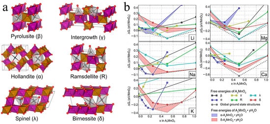
33]. Daniil et al. built an ab initio model using the SCAN function to reveal the effect of doping different guest ions on the formation of manganese dioxide with different phases, as depicted in
Figure 1a [
31]. As shown in
Figure 1b, the doping of Na, K, and Ca
++2+ was more likely to form α-MnO
2, whereas Li and Mg
+2+ favored the formation of γ-MnO
2, and δ-MnO
2 was easily stabilized by Na. The mechanistic basis was that distinct metal ion doping resulted in varied formation free energies required for the different phases of manganese dioxide. Hu et al. demonstrated that partial Mg
+2+ intercalation resulted in tunnels of various sizes, such as 3
× 3, 4
× 3, and 5
× 3 tunnels in T-MnO
2, not just 3
× 3 tunnels [
32]. Furthermore, the synthesis methods and synthesis circumstances also have a significant impact on the electrochemical performance of manganese oxides. Up to now, various synthesis methods have been widely applied in ion doping, including the hydrothermal method, ion penetration/exchange method, electrodeposition method, and calcination treatment.
Figure 1. (
a) Crystal structures of various manganese-based oxides [
31]. (
b) The formation free energies for A
xMnO
2·H
2O when doping with Li, Na, K, Mg
+++2+, and Ca
2+ [
31].
2.1. Hydrothermal Method
Because of its simple controllability over the diverse crystal phases of manganese-based oxides, hydrothermal synthesis is the most frequently used approach for ion doping. Ion doping can be controlled by the addition of the different ions in the raw solutions before hydrothermal treatment. Zhang et al. prepared α-K
0.19MnO
2 nanotubes via decomposition of KMnO
4 combined with carbon nanofibers as templates in 2019 [
34]. Under the hydrothermal conditions of 140 °C for 10 h, a typical K-doped tunnel structure was achieved. The reaction mechanism was as follows: K + MnO
++4− + C + H
2O → δ-K
0.19MnO
2·nH
2O + CO
32− + HCO
3−. Through a similar route, MnO
2H
0.16(H
2O)
0.27 nanolayers were synthesized via the reaction of KMnO
4 with acetylene black at 120 °C for 24 h by Pan et al. [
35]. Interestingly, this new phase exhibited excellent rate capability (115.1 mAh·g
−1 at 10 °C) with robust structural stability even with an interlayer spacing of less than 0.3 nm. Moreover, they developed a layered K
0.36H
0.26MnO
2·0.28H
2O via the neutralization reaction of KMnO
4 and MnSO
4 with K
2SO
4 additive as an excellent cathode in ZIBs [
36]. The layer-type structure of monoclinic birnessite phase was obtained following a hydrothermal reaction of 120 °C for 12 h with a large interlayer spacing (7.12 Å). Shi et al. synthesized a cathode (K
0.29MnO
2·0.67H
2O) with a larger interplanar spacing (7.4 Å) through a hydrothermal potassium insertion strategy [
37]. Peng et al. developed a Na-incorporated layered δ-MnO
+2 by subjecting K-containing δ-MnO
+2 to hydrothermal treatment using a 0.5 mol·L
−1 Na
2SO
4 solution at 180 °C for 3 h [
38]. Layered Ca
0.28MnO
2·0.5H
2O was synthesized by Tao et al. through a hydrothermal method at 160 °C for 12 h using CaCl
2, KMnO
4, and MnSO
4 as reactants with a molar ratio of 1:6:1 [
39]. This work demonstrated that divalent alkaline earth metal ions could also support layered manganese oxides, resulting in excellent electrochemical performance. Li et al. successfully incorporated Ni
2+ into α-MnO
2 for boosting the diffusion kinetics of protons in the tunnels, which proved the substitution of divalent metal ions for Mn sites in tunnel-type manganese based oxides [
40]. Du et al. found that the addition of Ce
3+ ions during hydrothermal synthesis could induce a phase transition of MnO
2 from β to α, which resulted in a larger tunnel structure (2.3
× 2.3 Å
2 vs. 4.6
× 4.6 Å
2) [
41]. Wang et al. developed a Bi
3+-doped α-MnO
2 cathode with an enlarged lattice spacing [
42]. First, Bi(NO
3)
3 and MnSO
4 were mixed uniformly; then, KMnO
4 was added and stirred for 2 h, before being transferred to a 100 mL autoclave and reacting at 120 °C for 12 h. Yan at al. also designed Al-intercalated α-MnO
2 using a hydrothermal approach with a narrower electronic bandgap [
43]. Interestingly, Al-doped MnO
2 exhibited a sea urchin-like morphology with a size of 4.5–5.0 µm and an enlarged interlayer spacing (0.24 nm vs. 0.29 nm). Xiong et al. reported that Al-doped α-MnO
2 coated with lignin was formed through a hydrothermal reaction involving KMnO
4, NH
4F, Al
2(SO
4)
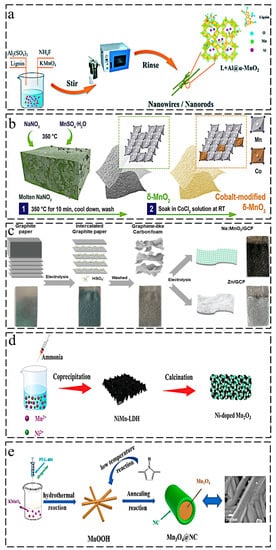
3, and lignosulfonate at 200 °C, as illustrated in
Figure 2a [
44].
Figure 2. Synthesis methods of ion-doped manganese-based oxides: (
a) hydrothermal synthesis of Al-doped α-MnO
2 coated with lignin [
44]; (
b) ion penetration method for cobalt-modified δ-MnO
2 [
47]; (
c) electrodeposition method for Na-doped δ-MnO
+2@GCF [
48]; (
d) calcination treatment for Ni-doped Mn
2O
3 [
52]; (
e) schematic illustration of the synthesis of Mn
3O
4@NC cathode [
63].
2.2. Ion Penetration/Exchange Method
The use of manganese oxides as precursors and the subsequent introduction of guest ions through a post-treatment process are more straightforward ideas for the ion doping strategy. Dai et al. developed a porous H
xMn
2O
4 cathode using a cation exchange strategy, which exhibited a novel crystal structure with an excellent cycle stability (1000 cycles at 1 A·g
−1) [
45]. First, they used ZnSO
4 as the zinc source, MnSO
4 as the manganese source, and NH
4HCO
3 for the coprecipitation reaction to obtain ZnCO
3-MnCO
3 composites, followed by high-temperature treatment at 600 °C for 3 h to obtain the ZnMn
2O
4 precursor, which was finally dispersed into 0.5 M H
2SO
4 ion exchange solution for 12 h to get H
xMn
2O
4. The mechanism of zinc-ion extraction by H was the disproportionation of Mn
+3+ and [ZnO
4] tetragonal distortion. This distinctive spinel-type cathode offered new opportunities for long-life span ZIBs. Banerjee et al. reported that a Cu-intercalated MnO
2 layered cathode was attained by mixing the prepared MnO
2 powder with a 1 M CuSO
4 solution for 48 h [
46]. The penetration of Cu
2+ into δ-MnO
2 resulted in an enlarged lattice spacing, thereby lowering the charge transfer resistance. Furthermore, they exploited the redox potential of Cu for full capacity using two electrons. A cobalt-modified δ-MnO
2 with a redox-active surface showed superior self-recovery capability, as reported by Shao et al. [
47]. As shown in
Figure 2b, a molten-salt method was adopted to synthesize δ-MnO
2 using MnSO
4·H
2O and NaNO
3 as the reactants, and then δ-MnO
2 powder was mixed with 1 M CoCl
2 aqueous solution by constant stirring for 8 h at room temperature. The deposition–dissolution mechanism was proven by the electrochemical performance (over 500 mAh·g
−1), and Co
2+ played a catalytic role in the electrochemical deposition of Mn
2+. In addition, a Mn
2+ additive was introduced into the electrolyte for enhanced cycle-stability.
2.3. Electrodeposition Method
Electrodeposition methods often involve depositing an electrolyte onto a conductive substrate by applying a certain current or voltage, which has the advantage of outstanding conductivity because of the highly conductive substrate. Dai et al. prepared a Na-doped MnO
+2@GCF cathode via the electrodeposition of 0.1 M Na
2SO
4 and 0.05 M MnSO
4·H
2O onto a graphene-like carbon film (GCF) [
48]. The cathode was synthesized through a two-step procedure. As illustrated in
Figure 2c, they first transformed the raw graphite paper into GCF by electrodepositing it into H
2SO
4 electrolyte, which had a 2D–3D hybrid network composed of graphene sheets. Then, the H
2SO
4 electrolyte was replaced by NaSO
4 and MnSO
4·H
2O to obtain Na-doped MnO
+2@GCF. The prepared cathode achieved excellent energy density (511.9 Wh·kg
−1 at 137 W·kg
−1). A Co–MnO
2 membrane was electrodeposited onto N-decorated carbon cloth (N-CC) by Nakayama et al. [
49] in 2020, using an electrolyte consisting of MnSO
4, ZnSO
4, and CoSO
4. Furthermore, the cathode delivered an impressive capacity of 280 mAh·g
−1, even at 1.2 A·g
−1. Wang et al. reported the electrodeposition synthesis of multivalence cobalt-doped Mn
3O
4 (Co-Mn
3O
4) [
50]. Similarly, a pretreated carbon cloth was applied as the substrate, while the cobalt and manganese sources were Co(CH
3COO)
2·4H
2O and Mn(CH
3COO)
2·4H
2O, respectively. Moreover, cobalt was present in multiple valence forms in the manganese oxides and played different roles, resulting in improved charge/ion transport and enhanced structure stability.
2.4. Calcination Treatment
Calcination treatment can provide high kinetics for guest ion intercalation, which is also applicable for manganese-based oxide doping strategies. Low-bandgap Ni
xMn
3−xO
4 nanoparticles were synthesized by Guo et al. through different calcination processes using manganese acetate as the manganese source and nickel acetate as the additive [
51]. A Ni–Mn-layered double hydroxide-derived Ni-doped Mn
2O
3 (NM) was developed by Huang et al. [
52]. First, the precursor Ni–Mn-LDH was formed by adding ammonia to a mixture of Ni(NO
3)
2·6H
2O, MnSO
4·H
2O, and NH
4F for coprecipitation at room temperature, and then Ni-doped Mn
2O
3 was obtained by calcining the precursor at 450 °C, as depicted in
Figure 2d. A metal–organic framework template strategy was adopted by Sun et al. to synthesize a N-doped Mn-based cathode (MnO
x@N-C) [
53]. Firstly, MnO
2 was generated by decomposing potassium permanganate under an acidic environment, and then MnO
2 was mixed with PVP, Zn(NO
3)
2·6H
2O, and 2-methylimidazole at room temperature to produce PVP-modified MnO
2@ZIF-8. Finally, MnO
x@N-C was obtained via calcination of MnO
2@ZIF-8 at 700 °C. Xia et al. fabricated a N-doped MnO
2–x cathode by calcining MnO
2 at 200 °C under an NH
3 atmosphere [
54]. MnO
2 was deposited on TiC/C via KMnO
4 decomposition, while N doping was processed by NH
3 treatment at low temperature. Li et al. designed a N-doped Na
2Mn
3O
7 (N-NMO) in combination with sodium pre-intercalation and nitrification strategies [
55]. In the first step, they used a chemical reaction involving KMnO
4, C
6H
12O
6, and NaKC
4H
4O
6 to synthesize rugby-type MnCO
3 particles as precursors. Next, Na
2Mn
3O
7 (NMO) was obtained by calcining MnCO
3 and NaNO
3 with a molar ratio of 3:2 at 600 °C for 4 h. Finally, N was introduced into NMO via further calcination under an ammonia atmosphere. Sun et al. reported that sulfur-doped MnO
2 (S-MnO
2) nanosheets were obtained using a two-zone furnace for application as a high-performance cathode [
56]. The S powder was placed on the upstream side under a temperature of 450 °C, while MnO
2 was placed on the downstream side under a temperature of 250 °C. This process was maintained for 1 h under Ar atmosphere.
3. Optimization Mechanism of Ion Doping in Zinc–Manganese Battery
Ion doping alters the behavior of electrode materials in a variety of ways. It is vital to produce a complete overview to develop better electrode materials and identify knowledge gaps for in-depth research in the future. As far as the current research progress is concerned, the positive effects of ion doping can be roughly divided into three categories: (1) enlarged interlayer spacing for improved ion diffusion kinetics, (2) defect engineering for enhanced electrical conductivity, and (3) pillar effect for enhanced stability of the host structure.
3.1. Enlarged Interlayer Spacing for Improved Ion Diffusion Kinetics
Theoretically, Zn
2+ ions have a small ionic radius (0.74 Å) and high ionic conductivity in aqueous solution (~1–10 mS·cm
−1) [
80]; however, in practice, due to their high charge density, Zn
2+ ions combine with water molecules to form hydrated [Zn(H
2O)
6]
2+, leading to an increment in ionic radius to 5.5 Å, slowing down the diffusion of Zn
2+. Furthermore, the solid electrostatic effect between Zn
2+ and the host structure of the cathode material also causes sluggish Zn
2+ intercalation [
81,
82]. The diffusion rate of carriers has a linear negative relationship with the electrostatic repulsion (ƒ) between the carriers and the host structure. According to the formula
ƒ∝1εrr20, where
εr is the permittivity and r
0 is the distance between Zn
2+ and the closest ions, a larger value of r
0 means faster diffusion kinetics [
21,
83]. In other words, a larger layer spacing leads to better diffusion dynamics. Ion doping is an efficient strategy to expand the layer spacing of the cathode material, thus enhancing performance.
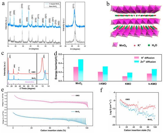
Kim et al. reported that V-doped MnO
2 (VMO) could enhance zinc storage properties by expanding the layer spacing [
74]. The (211) peak in the X-ray diffraction (XRD) patterns of VMO showed a minor shift toward lower scanning angles, as shown in
Figure 6a, confirming anisotropy of the unit cell parameters, which would facilitate the insertion of zinc ions. Lu’s group obtained a cathode with a larger interlamellar spacing by doping La
3+ into δ-MnO
2 (LMO), which showed lower resistance of Zn
2+ (de)insertion and better structural stability [
71]. The rate performance of LMO was significantly improved (121.8 mAh·g
−1 at 1.6 A·g
−1) compared to pristine δ-MnO
2 (only 3.4 mAh·g
−1 at 1.6 A·g
−1). Zheng et al. reported that phosphate ion-doped MnO
2 could expand the interlayer spacing of the (001) plane from 0.68 nm to 0.70 nm, accelerating ion transfer. Simultaneously, oxygen vacancies were introduced via phosphorization, enhancing the electrical conductivity of MnO
2 [
79]. Wang’s work revealed that the pre-intercalation of Bi
3+ into α-MnO
2 could effectively enlarge the lattice spacing and have a positive effect on the ion diffusion rates, resulting in a superior rate performance with a capacity retention of 150 mAh·g
−1 at 5 A·g
−1 [
42]. K
0.29MnO
2·0.67H
2O (KMO) with an interplanar spacing of 7.4 Å was synthesized via a simple hydrothermal strategy by Shi et al. [
37], as shown in
Figure 6b, exhibiting high capacity (300 mAh·g
−1 at 0.2 A·g
−1) and an ultralong cycle performance (158 mAh·g
−1 after 12,000 cycles at 2 A·g
−1). According to the XRD pattern in
Figure 6c, this work calculated that the interlayer spacing corresponding to the (001) plane increased from 6.8 Å to 7.4 Å according to Bragg’s rule. The diffusion energy barriers of H and Zn
+2+ in MnO
2 and KMO were explored using density functional theory (DFT)-based first-principles calculations, and the results revealed a lower value of KMO (0.11 eV and 0.19 eV) than MnO
2 (0.32 eV and 0.49 eV), as shown in
Figure 6d, indicating that the increased interlayer spacing indeed accelerated ion transfer. The kinetic behavior of the KMO sample was further investigated using the galvanostatic intermittence titration technique (GITT). As shown in
Figure 6e,f, KMO displayed a smaller overpotential and higher diffusion coefficient than MnO
2 during the discharge process, which indicated that the doping of K indeed promoted ion diffusion kinetics.
+
Figure 6. Enlarged interlayer spacing and faster ion diffusion kinetics: (
a) XRD patterns of V-doped MnO
2 [
74]; (
b) structure schematic of KMO [
37]; (
c) XRD patterns of KMO and MnO
2 [
37]; (
d) calculation results of H and Zn
+2+ diffusion energy barriers for KMO and MnO
2 electrodes using DFT [
37]; (
e) GITT image of KMO and MnO
2 electrodes [
37]; (
f) results of ion diffusion coefficients for KMO and MnO
2 electrodes [
37].
3.2. Defect Engineering for Enhanced Electrical Conductivity
For secondary batteries, electron transfer between the cathode and anode is an integral part of completing the whole electrochemical reaction; hence, the electrical conductivity of the cathode plays an important role in the electrochemical performance [
84]. However, manganese-based oxides are usually semiconductors with poor electrical conductivity [
85]. The strategy of complexing with conductive agents is generally adopted to accelerate electron transfer, while ion doping is another method to enhance the electronic conductivity of cathode materials [
86]. For example, a distinctive N-doped MnO
2−x cathode with numerous oxygen defects was prepared through NH
3 treatment at 200 °C by Xia et al. in 2019 [
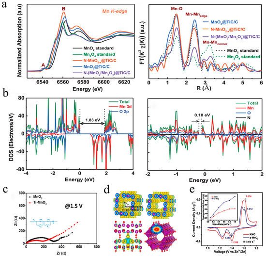
54]. Oxygen vacancies were introduced at the same time as N doping, which increased the electron density and lowered the bandgap of manganese dioxide, resulting in a better electronic conductivity and activity. As shown in
Figure 7a, the position of the absorption edge corresponding to the oxidation of N-doped MnO
2−x in the XANES spectrum presented a shift toward a lower energy, indicating higher average electron density. On the other hand, the FT spectrum implied that N-doped MnO
2 did not change phase but increased its level of disorder. The DFT calculation results (
Figure 7b) showed that N-doped MnO
2–x possessed a much smaller bandgap (0.12 eV) than pure MnO
2 (1.83 eV), revealing a significant enhancement of electronic conductivity. Excellent electrochemical performance was achieved that 285 mAh·g
−1 at 0.2 A·g
−1 with 85.7% retention after 1000 cycles at 1 A·g
−1. In the same year, Ti–MnO
2 with oxygen vacancies was reported by Mai’s group [
60], indicating that the replacement of manganese with titanium and the introduction of oxygen vacancies could break through the manganese–oxygen octahedral walls, resulting in heterogeneous charge distribution. As revealed by the EIS spectrum (
Figure 7c), Ti-doped MnO
2 exhibited lower charge migration resistance, confirming that the unbalanced local electric field in the host structure could boost the mobility of ions/electrons. Furthermore, according to the DFT calculations (
Figure 7d), the electron cloud of Ti substitution and its derived oxygen vacancies could balance the disordered interfacial electric field, allowing electron transit through the [MnO
6] octahedral walls. Liang et al. proposed a K-stabilized Mn-based cathode with rich oxygen defects (K
+0.8Mn
8O
16 with oxygen defects), which exhibited impressive stability over 1000 cycles with no obvious fading [
68]. As described in
Figure 4d,e, oxygen defects could accelerate H diffusion by opening the [MnO
+6] octahedral walls from the
ab-plane. Moreover, the oxygen defects could reduce the energy for electron and charge transfer during the redox reaction, as illustrated in
Figure 7e, KMO showed smaller overpotential gaps than pure MnO
2 (1.399/1.614 V vs. 1.389/1.612 V). More recently, Zhang et al. designed a cathode (O
cu–Mn
2O
3) by replacing sites of trivalent manganese with divalent copper ions to create oxygen defects in Mn
2O
3 for better electronic conductivity [
70]. Long et al. fabricated a low-bandgap cathode (Ni
xMn
3−xO
4) via the replacement of Mn with Ni. The DOS indicated that Ni-doped Mn
3O
4 exhibited a narrower bandgap than pure Mn
3O
4 (1.20 eV), thereby significantly enhancing the electronic conductivity [
51].
Figure 7. Defect engineering for improved electrical conductivity: (
a) XANES and FT spectra of N–MnO
2−x and MnO
2 [
54]; (
b) density of states results of MnO
2 and N–MnO
2−x [
54]; (
c) schematic illustration of charge density differences and charge transfer behavior in Ti–MnO
2 and MnO
2 electrodes [
60]; (
d) GITT profile of Ti–MnO
2 and MnO
2 electrodes; (
e) CV curves of KMO and α-MnO
2 [
68].