Your browser does not fully support modern features. Please upgrade for a smoother experience.
Please note this is an old version of this entry, which may differ significantly from the current revision.
In electrical machines, there are numerous negative phenomena of a destructive nature. The constructors of electrical machines try to limit these phenomena and/or minimize their negative effects. One such phenomenon in electrical machines is the occurrence of bearing voltages and currents. Despite their simple structure, the bearings are susceptible to damage to the raceway surface and rolling elements. Even small traces and imperfections of these surfaces may cause a serious failure resulting in the bearing being excluded from further operation.
- permanent magnet synchronous machine
- bearing voltage
- bearing current
- common-mode-voltage
- Finite Element Method
- calculation of capacitances
1. Introduction
Electric machines are among the largest consumers of electricity. They are widely used in many industries as components of drive systems for the entire power spectrum. Depending on the type of an electric machine and its application, its failure rate varies, as well as the nature and frequency of damage. The most common damages in electrical machines are: damage to bearings, insulation of stator windings, and defects of the rotor [1][2].
In electrical machines, as in any other devices, there are numerous negative phenomena of a destructive nature. The constructors of electrical machines try to limit these phenomena and/or minimize their negative effects. One such phenomenon in electrical machines is the occurrence of bearing voltages and currents. Despite their simple structure, the bearings are susceptible to damage to the raceway surface and rolling elements. Even small traces and imperfections of these surfaces (e.g., in the form of pits, stripes, abrasions, corrosion, etc.) [3][4] may cause a serious failure resulting in the bearing being excluded from further operation. The consequence of high temperatures during point sparking between the raceways of the bearing and the rolling elements is pitting. If an electric machine operates together with another mechanical device, e.g., a gearbox, the bearing current may close through the shaft [5] and other bearings included in the drive system; this contributes to premature failure of the bearings during operation. Examples of damage to motor components caused by the flow of bearing and shaft currents are presented for the bearing in Figure 1 and the shaft journal in Figure 2. The intensity of damage to bearings and shaft journals depends, among others, on the strength of the bearing current, its flow time, and the type of lubricant used [6]. The failure-free operation time of bearings strongly depends on the current density at the point where the oil film breaks. Accelerated wear of bearings is caused by local smelting of the raceway material and rolling elements when the local heat energy is too high. Shaft voltages and bearing currents occur to a greater or lesser extent in almost every rotating electric machine: both in AC machines and in DC machines [7].
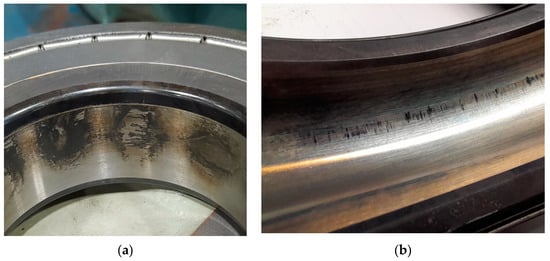
Figure 1. Irregular pitting of the bearing caused by the flow of bearing currents on the inner surface of the bearing (a) and the inner surface of the outer race of the bearing (b).
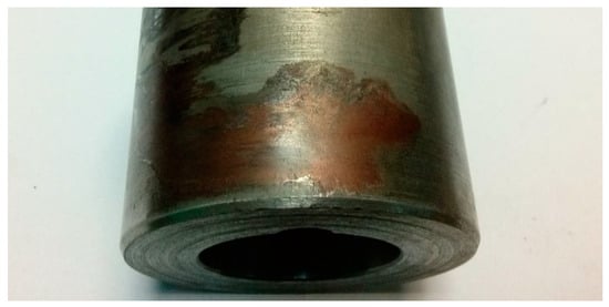
Figure 2. Damage to the outer surface of the shaft journal.
The available scientific and technical studies quite broadly describe the potential causes of shaft voltages in electrical machines and categorize their nature. The basic criterion for classifying the causes of generating shaft voltages in electric machines is the method of their power supply. There are different mechanisms of generating bearing voltages and currents if the machine is supplied with sinusoidal voltage or if it is supplied from a power electronic converter. Therefore, subsequent text, the causes, and methods of eliminating this phenomenon are presented separately for different power supplies of the machine.
2. Reasons for the Occurrence of Bearing Currents in Electric Machines with Sinusoidal Voltage Supply and Methods of Their Elimination
In the case of supplying an electric machine from the mains, the main reason for the generation of shaft voltage is the asymmetry of the electromagnetic circuit. It can result from both the technological tolerances of the machine as well as from the damages that are the consequence of the operation. Among the most important reasons are [5]: asymmetry of the air gap (dynamic or static), uneven air gap along the axis of the machine caused by the bending of the rotor (the primary cause is, for example, uneven magnetic tension along the shaft), inaccuracies in the execution of the stator and/or rotor iron core, anisotropy of the stator/rotor package sheets, ventilation channels in the stator and/or rotor package, stator sheets segmentation, asymmetry caused by short-circuit of a stator or rotor sheets, turn short-circuits in the windings, as well as cracks in the bars of the induction machine cage or its end rings.
The above reasons lead to the appearance of a circular flux in the stator’s yoke, which is the effect of the asymmetry of the main flux in the electromagnetic circuit [8]. This time-varying magnetic flux surrounding the machine shaft induces a shaft voltage which is the source of the current flowing through the shaft and the machine bearings. The publication [9] presents the idea of limiting shaft voltages based on the damping of this flux. For this purpose, an auxiliary winding was used, which was wound around the stator yoke. Magnetic flux asymmetry in the machine circuit results in inducing voltage at the terminals of the open auxiliary winding. When this winding is short-circuited, a current flows, which compensates the circular flux in the stator yoke, thus limiting the voltage on the machine shaft.
One of the methods of eliminating shaft currents in electric machines is the use of ceramic bearings (in which both raceways and rolling elements are ceramic) or hybrid bearings (only the rolling elements are made of a ceramic material) [3]. In such bearings, we obtain a large dielectric barrier along the path: shaft—bearings—bearing shields—frame.
3. Reasons for the Occurrence of Bearing Currents with Inverter Power Supply
The development of power electronic converters supplying electric motors contributed to the overall development of drive systems, enabling their operation at high supply frequencies, up to 1000 Hz [10]. One of the main sources of disturbances in drive systems is circuits with IGBT and MOSFET transistors. The issues mainly result from the high steepness (rise rate) of voltage and current growth that are present in the input and output circuits of the inverter. Fast switching of transistors in inverters contributes to the emergence of many unintentional phenomena, which include, among others: imbalance voltage caused by feeding the machine windings with distorted voltage, bearing voltages and currents, shaft voltages and currents, earth currents in grounded motors, decrease in motor efficiency, as well as the emission of electromagnetic disturbances. Due to the rapid development of technology, ever-newer methods of counteracting negative phenomena are currently being sought, not only through the use of appropriate filters but also through their elimination at the stage of designing the drive system. In order to improve the control conditions of AC electric machines powered by inverters, high control frequencies (up to several kHz) are used. Controlling the transistors with such high switching frequencies significantly reduces the noise generated in the drive system and makes it possible to obtain a sinusoidal shape of the current consumed by the motor. Nevertheless, if the switching frequency of the inverter power transistors is too high, it contributes to the excessive dissipation of power losses caused by the increased share of dynamic losses in relation to the static losses in the inverter while reducing the power losses generated in the electric machine.
Most of the frequency converters working with asynchronous and synchronous machines with permanent magnets work with the use of the space vector modulation (SVM) method, which enables independent regulation of speed and electromagnetic moment. Unlike machines powered by the sinusoidal voltage, the use of semiconductor power electronic systems is associated with the presence of non-zero voltage at the neutral point of the machine winding related to the earth’s potential. This voltage, referred to as common-mode voltage, is the average sum of the instantaneous voltage values (1) (asymmetric, rectangular voltage waveforms) at the converter output resulting from the use of pulse width modulation. The most frequently used inverters in drive systems with induction and synchronous machines are the three-branch two-level voltage inverters with adjustable amplitude and frequency. The scheme of the inverter is shown in Figure 3. In such inverters, the DC-link voltage is switched via the two-state power elements of the inverter (S1–S6). Each branch of the three-phase inverter can assume two different operating states while one of the two power valves of the inverter branch is turned on at a given moment. Thus, the three branches of the inverter can generate eight possible state combinations, represented by eight separate voltage vectors at the inverter power outputs.
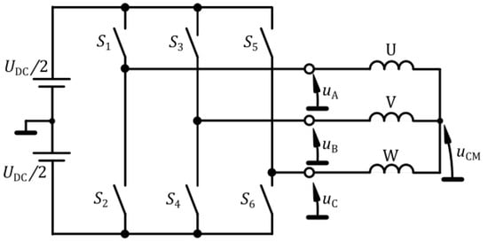
Figure 3. Schematic diagram of a two-level three-phase frequency converter with specified common-mode voltage uCM.
The basic control algorithm of the two-level power electronic converter consists of the appropriate control of six power electronic switches S1–S6, as shown in Table 1, which leads to the generation of the space vector of the output voltage. Figure 4 shows examples of phase voltages uA, uB and uC created with the use of the available operating states of the inverter switches. In each of them, there is an asymmetry of the output voltages, which results in the formation of common-mode voltage uCM (Figure 3). Thus, the resultant voltage uCM appears at the neutral point of the stator winding, which is expressed by the Formula (1):
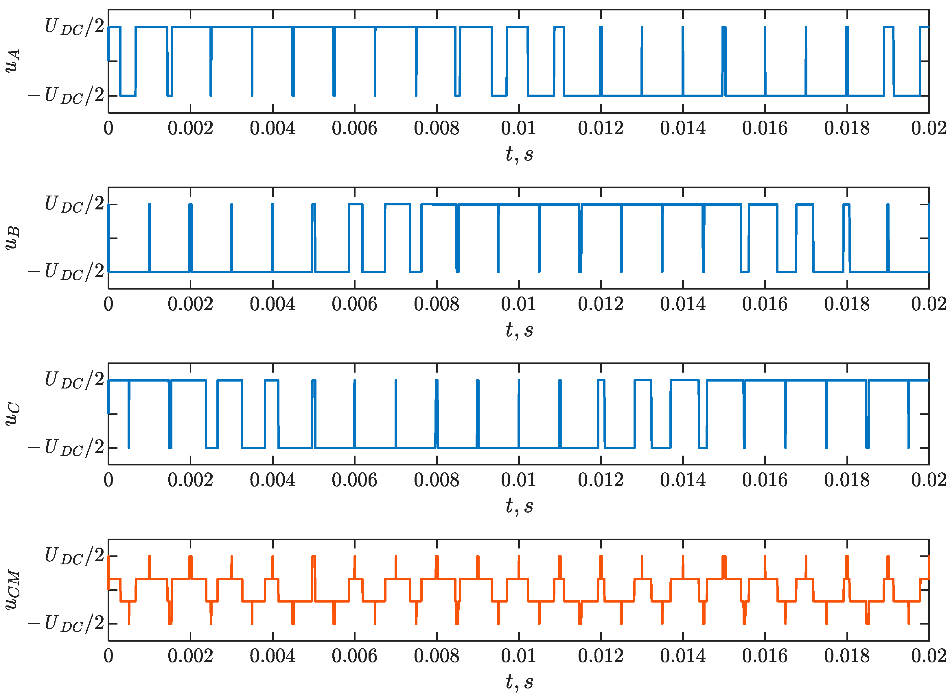
Figure 4. Sample waveforms of the phase output voltages of a two-level frequency converter uA, uB, uC and the common-mode voltage uCM.
Table 1. Summary of the common-mode voltage uCM values for individual control vectors.
| Vector | uA | uB | uC | uCM |
|---|---|---|---|---|
| 000 | −UDC/2 | −UDC/2 | −UDC/2 | −UDC/2 |
| 100 | UDC/2 | −UDC/2 | −UDC/2 | −UDC/6 |
| 110 | UDC/2 | UDC/2 | −UDC/2 | UDC/6 |
| 010 | −UDC/2 | UDC/2 | −UDC/2 | −UDC/6 |
| 011 | −UDC/2 | UDC/2 | UDC/2 | UDC/6 |
| 001 | −UDC/2 | −UDC/2 | UDC/2 | −UDC/6 |
| 101 | UDC/2 | −UDC/2 | UDC/2 | UDC/6 |
| 111 | UDC/2 | UDC/2 | UDC/2 | UDC/2 |
The common-mode voltage has the form of a step function of time with a maximum value equal to half of DC-link voltage UDC. The value of the voltage change on individual steps is 1/3 UDC; this is alternating voltage, with a frequency dependent on the switching frequency. The use of switches with short switching times (e.g., IGBT transistors) results in voltage rise rates in the inverter output voltages and the common-mode voltage, up to 10 kV/μs [11], especially in the case of using converters based on the SiC technology [12].
Rapid voltage increase duCM/dt at the neutral point of the stator winding stimulates the occurrence of capacitive couplings in the electrical machine and plays an important role in the mechanism of generating bearing currents. The stator windings of the electric machine are isolated from the stator core, and at the same time, the rotor is practically isolated from other structural elements due to the presence of an oil film in the bearings. As a consequence, a capacitance system is created between the structural elements of the motor, which in the subsequent text are referred to as the internal capacitances of the machine. The electrodes of these internal capacitances are the stator winding, stator and rotor cores, and their dielectrics are, among others, slot insulation, air gap, and oil film in the bearings. In the simplified model of the electric machine, the following capacitances can be distinguished: Cws—capacitance between the stator winding and the grounded stator; Cwr—capacitance between the stator winding and the rotor; Csr—capacitance between the rotor and the grounded stator; Cb1 and Cb2—bearing capacitances on the drive and non-drive end. The spatial location of the above-mentioned capacitances is illustrated in the cross-section of the electric machine in Figure 5. The topology and connection of these capacitances in the form of an equivalent circuit with lumped parameters are shown in Figure 6a [13].
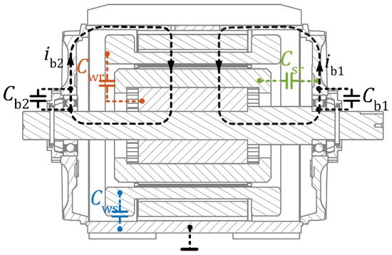
Figure 5. Internal capacitances in the electric machine.
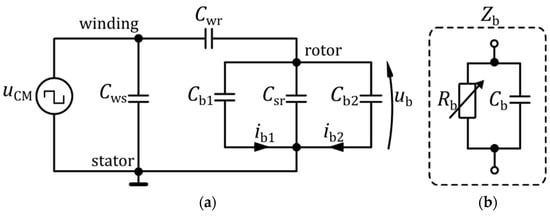
Figure 6. (a) Equivalent circuit diagram for the flow of the bearing current; uCM—common-mode voltage, ub—bearing voltage, description of other parameters in the text, (b) equivalent circuit of the bearing impedance Zb, composed of: bearing resistance Rb and capacitance Cb.
The value of the Cws capacitance depends on the geometrical dimensions of the machine and the configuration of the windings, as well as on the dielectric parameters of the used stator slot insulation, while the value of the capacitance Cwr depends on the shape and dimensions of the electromagnetic circuit. In terms of the electrical circuit, bearings are represented by impedance Zb that consists of a parallel connection of resistance Rb and capacitance Cb (Figure 6b).
The values of these parameters depend on the bearing structure, temperature, and the operating condition of the machine. During the normal operation of the machine, an oil film forms dielectric insulation between the rolling elements and raceways of the bearing. If lubricant is of poor quality or altogether missing, then if a voltage higher than the breakdown voltage appears, the impedance Zb is short-circuited. In the case of a stopped rotor, the bearing raceways are short-circuited by the rolling elements (no oil filter present), which causes a significant decrease in the resistance Rb. This condition is especially dangerous for the bearing when the motor is started. When the impedance Zb is short-circuited, a bearing current ib flows under the bearing voltage ub. The values of the equivalent circuit parameters can be determined by measurement, analytically [14][15] or using the finite element method. The bearing resistances are omitted here; an equivalent diagram that consists only of internal capacitances is used.
The equivalent diagram (Figure 6) shows that the common-mode voltage uCM is the source of the voltage between the bearing raceways ub. The ratio of these voltages (BVR—Bearing Voltage Ratio) is given by the Equation (2) [16]:
It is worth emphasizing that when the motors are supplied with sinusoidal voltage with the mains frequency f = 50 Hz, the internal impedances/reactances of the machine are very high (Xc = 1/ωC), and they are not significant in generating bearing voltages. The values of internal capacities are at the level of a few nF. They are important only when the machine windings are supplied from inverters, where voltage rise rates are high; therefore, the knowledge of their values is of fundamental importance from the point of view of determining, e.g., the values of bearing voltages.
This entry is adapted from the peer-reviewed paper 10.3390/en15124475
References
- Kudelina, K.; Asad, B.; Vaimann, T.; Rassõlkin, A.; Kallaste, A.; Khang, H.V. Methods of Condition Monitoring and Fault Detection for Electrical Machines. Energies 2021, 14, 7459.
- Deekshit Kompella, K.C.; Venu Gopala Rao, M.; Srinivasa Rao, R. Bearing Fault Detection in a 3 Phase Induction Motor Using Stator Current Frequency Spectral Subtraction with Various Wavelet Decomposition Techniques. Ain Shams Eng. J. 2018, 9, 2427–2439.
- SKF. SKF Bearing Maintenance Handbook; SKF: Göteborg, Sweden, 2011; ISBN 978-91-978966-4-1.
- Timken Bearing Damage Analysis with Lubrication Reference Guide; The Timken Company: North Canton, OH, USA, 2015.
- Costello, M.J. Shaft Voltages and Rotating Machinery. IEEE Trans. Ind. Appl. 1993, 29, 419–426.
- Zhou, Y.; Bosman, R.; Lugt, P.M. An Experimental Study on Film Thickness in a Rolling Bearing for Fresh and Mechanically Aged Lubricating Greases. Tribol. Trans. 2019, 62, 557–566.
- Plazenet, T.; Boileau, T.; Caironi, C.; Nahid-Mobarakeh, B. An Overview of Shaft Voltages and Bearing Currents in Rotating Machines. In Proceedings of the 2016 IEEE Industry Applications Society Annual Meeting, Portland, OR, USA, 2–6 October 2016; pp. 1–8.
- Chapter 2 Shaft voltages and their origin in rotating machines and flow of electric current through bearings. Tribol. Interface Eng. Ser. 2006, 49, 15–23.
- Berhausen, S.; Jarek, T. Method of Limiting Shaft Voltages in AC Electric Machines. Energies 2021, 14, 3326.
- Wolnik, T.; Styskala, V.; Mlcak, T. Study on the Selection of the Number of Magnetic Poles and the Slot-Pole Combinations in Fractional Slot PMSM Motor with a High Power Density. Energies 2021, 15, 215.
- Turzyński, M.; Musznicki, P. A Review of Reduction Methods of Impact of Common-Mode Voltage on Electric Drives. Energies 2021, 14, 4003.
- Collin, R.; Yokochi, A.; von Jouanne, A. Novel Characterization of Si- and SiC-Based PWM Inverter Bearing Currents Using Probability Density Functions. Energies 2022, 15, 3043.
- Muetze, A.; Binder, A. Calculation of Motor Capacitances for Prediction of the Voltage Across the Bearings in Machines of Inverter-Based Drive Systems. IEEE Trans. Ind. Appl. 2007, 43, 665–672.
- Stockbrügger, J.O.; Ponick, B. Analytical Determination of the Slot and the End-Winding Portion of the Winding-to-Rotor Capacitance for the Prediction of Shaft Voltage in Electrical Machines. Energies 2020, 14, 174.
- Muetze, A.; Binder, A. Calculation of Circulating Bearing Currents in Machines of Inverter-Based Drive Systems. IEEE Trans. Ind. Electron. 2007, 54, 932–938.
- Ahola, J.; Muetze, A.; Niemela, M.; Romanenko, A. Normalization-Based Approach to Electric Motor BVR Related Capacitances Computation. IEEE Trans. Ind. Appl. 2019, 55, 2770–2780.
This entry is offline, you can click here to edit this entry!