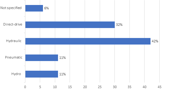
The overview of the types of wave energy converters (WECs) are classified through operational principle, absorbing wave direction, location, and power take-off.
- ocean wave energy
- wave energy converter
Note:All the information in this draft can be edited by authors. And the entry will be online only after authors edit and submit it.
1. Introduction
The sea surface waves provide a large amount of green energy and could make an enormous difference to global energy demands going toward the sustainable world. One of the factors that makes waves desirable for harvest is that they have tremendous power density compared to many renewable energy sources [1]. Wave energy seems to have the second-highest potential of all ocean clean energy sources [2,3]. The theoretical potential of wave energy is shown in Table 1. Wave energy sources have been evaluated at global [4–6] and regional [7–10] levels and the volume of wave energy available is high enough to stimulate significant interest in exploitation. The estimated worldwide demand in 2014 for electrical energy reached 19,800 TWh/year [11] with a worldwide wave energy reserve of the same extent [12]. However, estimates of theoretically usable wave energy capacity on a worldwide scale are widely recorded between 2000 and 4000 TWh/year [13]. Environmental problems, including air pollution, global warming, and severe weather, due to colossal fossil oil use are gradually being discussed. For electricity generation in 2040, fossil fuels are expected to account for greater than 35% of the total energy consumption [14]. In this sense, it is much more essential to harness renewable energy sources such as wind, solar, and ocean wave energy.
China, America, India, and European countries are on the frontline of establishing strategies for incorporating the wave energy of the ocean into their systems [15]. Government agencies within these countries funded studies to carry out resource assessments [16] and provided test sites and laboratories for the development and planning of energy conversion systems [17–19]. Apart from state-funded studies, some studies are conducted by universities [20], private organizations [21], research centers [22], and individuals who are all involved in an attempt to promote ocean energy into the public consciousness of a renewable energy sector. Due to the immense potential of wave energy [1], a wide range of wave energy converter (WEC) ideas has been formed to capture energy from waves. It is noted that now there are more than 1000 WEC prototypes [23,24]. Different studies have identified challenges resulting from the volatility of the properties of ocean waves and the sustainability of energy converters of the waves in a severe ocean environment [25].
The stability of the wave energy converter requires a mooring system. Present mooring systems and design specifications cannot completely fulfill the demands of the offshore WECs. It is according to the four properties of the wave energy converters which place them apart from the other offshore installations: function, operation, investment/revenue relationship, and the consequences in the event of failure. In the case of offshore WECs, the failures of a mooring system seem to be minor compared to offshore platforms. As such, strict safety requirements are not required. However, recommended offshore standards are needed for the implementation, and this results in the total investment between 18% [26] to 30% [27] in mooring systems. To optimize the energy efficiency of the wave energy converters, they need to be deployed to high-energy zones. Those are areas where the wave condition is high and, as a result, where a converter and also its mooring mechanism would be under extreme loading. Some of the WEC types are motion-dependent that require oscillations in waves, mostly in resonance, to obtain energy. Such oscillations will cause a mooring system to make high amplitude motions at a high frequency, causing higher dynamic tensions in mooring lines, mainly when it is in resonance. The performance of the motion-dependent devices is affected by the mooring system, because as mooring lines adding their mass (added mass), damping, and stiffness it changes the dynamic responses of WECs. The mooring system mass and stiffness are not detrimental and may also increase the performance of the converter, as stated in reference [28]. In addition, the additional mooring damping, contributing to the stabilization of floating structures [29], dissipates energy that may be exploited by WECs that are motion dependent.
An excellent mooring system for floating WECs will consider not only the possible consequences of the power take-off and device motions and but also ensure stability, be easy to maintain and monitor, and reduce installation and material costs. In this paper, the overview of the types of WECs and their mooring configurations, components, requirements, modeling approach, design consideration, suitable software, and challenges are discussed.
Table 1. Global resources of wave energy [30].
|
World Regions |
Wave Energy Potential (TWh/y) |
|
Asia |
6200 |
|
New Zealand, the Pacific Islands, and Australia |
5600 |
|
South America |
4600 |
|
North America and Greenland |
4000 |
|
Africa |
3500 |
|
Western and Northern Europe |
2800 |
|
Central America |
1500 |
|
The Mediterranean Sea and Atlantic Archipelagos |
1300 |
|
Total |
29,500 |
2. WECs
The conversion of wave energy into useful energy, such as electricity, is performed through WECs.
2.1. Historical Background
The prospect of conversion of wave energy to useful energy has encouraged various inventors: by 1980, more than 1000 patents were already registered [31] and since then, the number had risen considerably. In 1799, Girard filed the earliest best known such patent in France [32]. By the late-twentieth century, several patents relating to the conversion of wave energy were in existence [33]. Former Japanese naval chief Yoshio Masuda can be called the founder of advanced wave energy development. He developed a navigation buoy equipped with a wave-driven air turbine. Such buoys are the components of the oscillating water column (OWC) [34]. The revival of wave energy work within the 1970s–1980s was mainly a result of oil crises in 1973, and the crises generated recognition of the spatial and temporal importance of the reserves of fossil fuel to policymakers and governments [35,36]. Governments [37,38] and intergovernmental associations, thus, spearheaded several developments and research activities. The 1973 oil crisis sparked a significant shift in the scenario of renewable energies and increased interest in wave energy generation on a full scale. In 1974, Stephen Salter introduced wave energy to the community of researchers and had become a landmark [39].
Several articles on the conversion of wave energy were written as books, journal papers, reports, and conference papers, such as McCormick's pioneering book [31], released in 1981, and the books of Shaw [40], Justus and Charlier [41] (finished wave energy long chapter in 1986), Cruz [42], Ross [32], and Brooke [43]. In 1999, a report prepared by the Energy Department of the UK [2] and final report on wave energy (2003) [44] from the Thematic Network of European (European-Commission-funded project) provide a wide variety of data. Shorter reviews are available [45–47].
2.2. Wave Energy Converter Classifications
To date, numerous different methods have been developed to convert the wave energy to electrical energy. Around 53 different technologies of wave energy were reported in reference [48] in 2006. Typically, they are classified as per conversion type. The classifications of WECs are more in detail in references [49–51].
2.2.1. Operational Principle
The operating principle describes how the wave energy converter interacts and absorbs energy from incoming waves. Falcão has proposed classification by operating principle [52].
Oscillating water column (OWC): The OWC is a floating hollow or fixed device that compresses and decompresses compressed air using the change in wave induced in the water level within the chamber [53], as shown in Figure 1. The pressure difference in the chamber forces air to move via a turbine that is coupled with the generator. If built near the shore, OWCs will act like breakwater structures to secure the coastline [54]. Some OWC devices have a natural installation advantage when installed close to the shore. Some examples are Energetech [55], OceanLinx [56], WaveGen Limpet [57], Yongsoo Power Plant [53], and Pico OWC [58]. Some examples of floating OWCs include Mighty Whale [59], the Spar Buoy [60], and Backward Bent Duct Buoy [61].
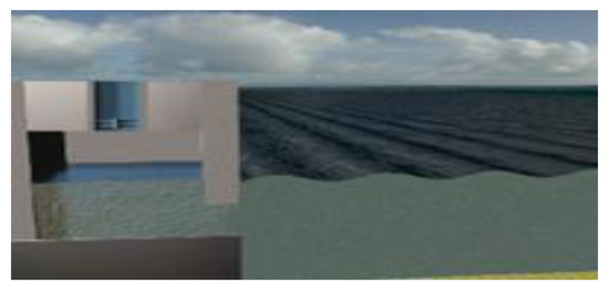
Figure 1. Oscillating water column [62].
Oscillating bodies: Oscillating body is a generic term used to identify WECs that derive power from wave-induced oscillations of submerged or floating structures primarily in surge or heave.
Heaving type devices are commonly constructed as axisymmetric buoys just below or on the surface of the water, extracting power from the wave's vertical motion. A total of 74 listed companies of wave energy by the Marine Energy Centre in Europe [63] concentrate on the production of heaving type point absorbers. These include Cor Power WEC (floating WEC of bottom-referenced connected to pneu-mechanical drive) [64], Power Buoy [65] (floating system of two-body self-referenced with hydraulic power take-off (PTO), as shown in Figure 2), the CETO system [66] (submerged converter of bottom-referenced with hydraulic PTO), and Sea-based wave energy converter [67] (floating system of bottom-referenced coupled with linear generator).
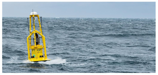
Figure 2. Power buoy [65].
Oscillating wave surge (OWSC) converters are made up of the flapping structure, for example, as a plate, hinged on the seafloor or submerged reference base, as shown in Figure 3. There are currently 14 different oscillating wave surge converters developed around the world [63], including BioWare, Langlee, and Oyster. The (OWSC) power output is lower compared to bottom-fixed because the reference base that is built to be stable always tends to pass in waves and often does not have an appropriately high reaction point of impedance [68].
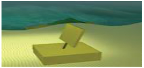
Figure 3. Oscillating wave surge converter concept [62].
Submerged pressure differential: In general, this device's position is near the shore and anchored to a seabed [62]. They usually are submerged point absorbers fixed and located near shore [69] and are Comprised of one or more chambers that are air-filled in which the pressure fluctuates based on the incident wave phase (trough or crest). The changing pressure in the presence of deformable chambers results in a continuous airflow within the device, which is converted by air turbine into electricity. This concept is found in the Bombora WEC [70]. The air chamber for rigid structures consists of one constant and one rotating component where there is a variation for chamber volume due to the changing pressure. The moving component down and up motions transform into electricity by the linear generator; it is applied in Archimedes Wave Swing [71], as shown in Figure 4.
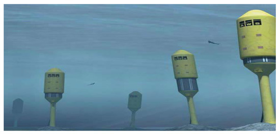
Figure 4. Archimedes Wave Swing [62].
Overtopping: The overtopping mechanism consists of a water reservoir above the surface level of the ocean, which causes the water of the reservoir to transfer to the sea through the turbine structure. The overtopping earliest devices in Norway are the wave power tapered channel devices (Tapchan) [72]. They have a 350kW nominal power. Wave Dragon is another conventional device and is a floating device designed in Denmark [73], as shown in Figure 5. The design of the slope Seawave Cone Generator [74] is similar to the Wave Dragon. Wave Dragon is a universal application that uses as overtopping devices, and the Wave Dragon structure is shown in references [73,75]. Wave Dragon is a multiple MW plant of production with maximum power take-off performance and fast maintenance. Moreover, because of its large size, it is costly. Wave Dragon covers a vast region of the ocean and has an environmental impact.
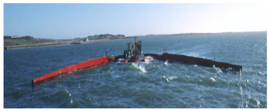
Figure 5. Wave Dragon [73].
Since these WECs have substantially different performances, the estimated hydrodynamic efficiency is shown in Table 2, and WECs’ breakdown by the principle of operation is shown in Figure 6.
Table 2. Different wave energy converters’ (WECs’) efficiencies [76,77].
|
WEC Device Type |
Efficiency % |
|
Pressure differential |
38 |
|
Oscillating water column (OWC) |
29 |
|
Overtopping |
17 |
|
Oscillating body—Heaving |
16 |
|
Oscillating body—Surging |
37 |
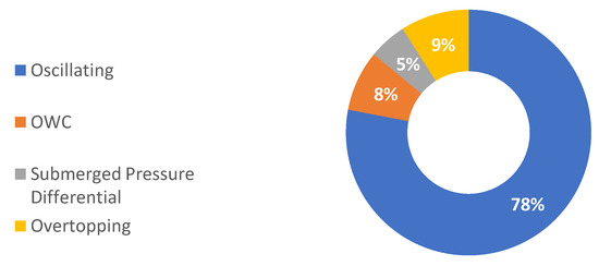
Figure 6. WECs, based on the operational principle [78].
2.2.2. Direction
The WECs, according to the wave propagation direction, are classified as follows:
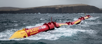
Attenuator: Usually, the attenuator is a flexing device, mounted parallel with the direction of propagation of the wave. An attenuator works by absorbing the energy from their two arms' relative motion when the wave moves through them. This device is also a floating-type device that acts in parallel with the path of the wave and drives the waves efficiently [62]. The Pelamis [79] is a typical example. Three Pelamis units formed the commercial world's first wave-farm of Portugal's coast in September 2008 [80], as shown in Figure 7.
Figure 7. Pelamis wave farm [81].
Terminator: This device intercepts waves by standing perpendicular to a prevailing direction of the wave [82,83]. The device Salter’s Duck, invented by Dr. Stephen Salter at Edinburgh University in 1978, is probably the most known of this kind, as shown in Figure 8.
Figure 8. Salter's Duck [65].
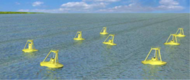
Point absorber: Point absorber has considerably smaller dimensions than a wavelength and can produce power independently of the direction of the wave propagation. The buoy can oscillate to one degree of freedom or more, as shown in Figure 9. A motion of the buoy damping extracts energy, and a generator converts it into electricity. A pitching type point absorber is the example of the Salter’s Duck [39]. Wave Star [84], FO3 [85], and Manchester Bobber [86] are heaving type multipoint absorber devices.
Figure 9. Point absorber [62].
Quasi-point absorber: Presented by Hals and Falnes [87], quasi-point absorbers characterize axisymmetric WECs, which are unresponsive to the direction of wave (like point absorbers) but have fairly broad dimensions comparable to wavelengths (like terminators).
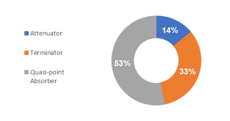
A summary of WECs based on orientation is shown in Figure 10.
Figure 10. WECs based on orientation [78].
2.2.3. Location
Wave energy converters are classified based on the location as offshore, nearshore, and onshore.
Offshore locations: A higher energy level of waves in deep water makes the offshore devices more impressive for the production of wave power [83]. Offshore devices, due to the severe climatic conditions, can sustain larger loads; however, they are much more challenging to deploy and operate.
Nearshore: These devices are referred significantly to as lower water in which converters are attached commonly to an ocean floor. The example of a nearshore type device is WaveRoller [88].
Onshore: Onshore devices are fixed on the shoreline, with the benefit of being easy to maintain and install. Furthermore, moorings of deep water are not required, and the risk of storm damage to onshore devices is minimal, but the wave regime is less efficient.
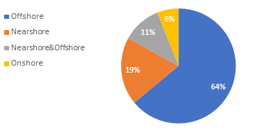
A summary of WECs based on location is shown in Figure 11.
Figure 11. WECs based on location [78].
2.2.4. Power Take-off
Typically, recognized power take-off (PTO) is the process where energy passed between the WEC and the waves, directly or subsequently, turns into a usable form [89]. The types of PTO include hydraulic, hydro, pneumatic, and direct-drive, and their efficiencies are shown in Table 3. The critical challenge of the development of PTO is that the machines must work at lower speeds and higher forces, whereas typical electrical generators are planned for low torque and higher speed motion. Although the efficiency of the hydraulic system is relatively low (see Table 3), it is most suitable for extracting wave energy, as seen in Figure 12 and further WEC examples with their (PTO) systems presented in Table 4.
Advancements and improvements continued in the wave energy sector, and a detailed assessment of power take-off is provided in reference [90].
Table 3. Power take-off (PTO) systems’ efficiencies [91].
|
WEC Device Type |
Efficiency % |
|
Hydro |
85 |
|
Pneumatic |
55 |
|
Hydraulic |
65 |
|
Direct mechanical drive |
90 |
|
Direct electrical drive |
95 |
Figure 12. WECs based on PTO principle [78].
Table 4. WEC examples with their (PTO) system.
|
Name of WEC |
Type of WEC |
PTO |
References |
|
Pelamis |
Pitching system |
Hydraulic system |
[92] |
|
Wavebob |
Heaving body |
Hydraulic system |
[93] |
|
SEAREV |
Pitching system |
Hydraulic system |
[94] |
|
REWEC3 |
OWC |
Wells turbine |
[95] |
|
Sakata |
OWC |
Wells turbine |
[96] |
|
AquaBuoy |
Heaving body |
Impulse turbine |
[97] |
References
- Clément, A.; McCullen, P.; Falcão, A.; Fiorentino, A.; Gardner, F.; Hammarlund, K.; Lemonis, G.; Lewis, T.; Nielsen, K.; Petroncini, S.; et al. Wave energy in Europe: Current status and perspectives. Sustain. Energy Rev. 2002, 6, 405–431.
- Thorpe, T.W. A Brief Review of Wave Energy; Harwell Laboratory, Energy Technology Support Unit: London, UK, 1999.
- Ilyas, A.; Kashif, S.A.R.; Saqib, M.A.; Asad, M.M. Wave electrical energy systems: Implementation, challenges and environmental issues. Sustain. Energy Rev. 2014, 40, 260–268.
- Mork, G.; Barstow, S.; Kabuth, A.; Pontes, M.T. Assessing the Global Wave Energy Potential. In Proceedings of the OMAE2010 29th International Conference on Ocean, Offshore Mechanics and Arctic Engineering, Shanghai, China, 6–11 June 2010.
- Izadparast, A.H.; Niedzwecki, J.M. Estimating the potential of ocean wave power resources. Ocean Eng. 2011, 38, 177–185.
- Mollison, D. Hydrodynamics of Ocean Wave-Energy Utilization; Springer: Berlin, Germany, 1986; pp. 133–156.
- Lenee-Bluhm, P.; Paasch, R.; Özkan-Haller, H.T. Characterizing the wave energy resource of the US Pacific Northwest. Energy 2011, 36, 2106–2119.
- Iglesias, G.; López, M.; Carballo, R.; Castro, A.; Fraguela, J.A.; Frigaard, P. Wave energy potential in Galicia (NW Spain). Energy 2009, 34, 2323–2333.
- Citiroglu, H.K.; Okur, A. An approach to wave energy converter applications in Eregli on the Western Black Sea Coast of Turkey. Energy 2014, 135, 738–747.
- Haces-Fernandez, F. Investigation on the Possibility of Extracting Wave Energy from the Texas Coast. Master’s Thesis, Texas A&M University Kingsville, Kingsville, TX, USA, 2014.
- IEA–International Energy Agency. Available online: https://www.iea.org/ (accessed on 20 July 2020).
- Cruz, J. Ocean Wave Energy Current Status and Future Perspectives; Springer: Berlin, Germany, 2008.
- IRENA–International Renewable Energy Agency. Available online: https://www.irena.org/ (accessed 20 July 2020).
- Jones, N. The Outlook for Energy: A View to 2040; Technical Report by Exxon Mobil Corporation: Spring, TX, USA, 2015.
- Annual Report Ocean Energy Systems. Available online: https://report2016.ocean-energy-systems.org/ (accessed on 20 July 2020).
- Jacobson, P.T.; Hagerman, G.; Scott, G. Mapping and Assessment of the United States Ocean Wave Energy Resource; Electric Power Research Institute: Palo Alto, CA, USA, 2011.
- Lawrence, J.; Kofoed-Hansen, H.; Chevalier, C. High-Resolution Metocean Modelling at EMEC’s (UK) Marine Energy Test Sites. In Proceedings of the 8th European Wave and Tidal Energy Conference, Uppsala, Sweden, 7–10 September 2009.
- Neary, V.S.; Lawson, M.; Previsic, M.; Copping, A.; Hallett, K.C.; LaBonte, A.; Murray, D. Methodology for Design and Economic Analysis of Marine Energy Conversion (MEC) Technologies; Sandia National Lab. (SNL-NM): Albuquerque, NM, USA, 2014.
- Cada, G.; Ahlgrimm, J.; Bahleda, M.; Bigford, T.; Stavrakas, S.D.; Hall, D.; Moursund, R.; Sale, M. Potential impacts of hydrokinetic and wave energy conversion technologies on aquatic environments. Fisheries 2007, 32, 174–181.
- Brekken, T.K.; Von Jouanne, A.; Han, H.Y. Ocean wave energy overview and research at Oregon State University. In Proceedings of the Power Electronics and Machines in Wind Applications, Lincoln, NE, USA, 24–26 June 2009.
- Ocean Power Technologies. Available online: https://oceanpowertechnologies.com/new-homepage-alt/ (accessed on 20 July 2020).
- Whittaker, T.; Collier, D.; Folley, M.; Osterried, M.; Henry, A.; Crowley, M. The Development of Oyster A Shallow Water Surging Wave Energy Converter. In Proceedings of the 7th European Wave and Tidal Energy Conference, Porto, Portugal, 1 September 2007.
- Pelc, R.; Fujita, R.M. Renewable energy from the ocean. Policy 2002, 26, 471–479.
- Czech, B.; Bauer, P. Wave energy converter concepts: Design challenges and classification. IEEE Ind. Electron. Mag. 2012, 6, 4–16.
- Lehmann, M.; Karimpour, F.; Goudey, C.A.; Jacobson, P.T.; Alam, M.-R. Ocean wave energy in the United States: Current status and future perspectives. Sustain. Energy Rev. 2017, 74, 1300–1313.
- Fitzgerald, J. Position Mooring of Wave Energy Converters. Ph.D. Thesis, Chalmers Univerisity of Technology, Gothenburg, Sweden, 2009.
- Martinelli, L.; Ruol, P.; Cortellazzo, G. On Mooring Design of Wave Energy Converters the Seabreath Application. In Proceedings of the 33rd International Conference Coastal Engineering, Padua, Italy, 1–6 July 2012.
- Fitzgerald, J.; Bergdahl, L. Including moorings in the assessment of a generic offshore wave energy converter: A frequency domain approach. Struct. 2008, 21, 23–46.
- Webster, W.C. Mooring-induced damping. Ocean Eng. 1995, 22, 571–591.
- Wave Energy Technology Brief. 2014. Available online: www.irena.org (accessed on 21 July 2020).
- McCormick, M.E. Ocean Wave Energy Conversion; Courier Corporation: North Chelmsford, MA, USA, 1981.
- Ross, D. Power from the Waves; Oxford University Press: New York, NY, USA, 1995.
- Falnes, J. A review of wave-energy extraction. Struct. 2007, 20, 185–201.
- Masuda, Y. An experience of wave power generator through tests and improvement. In Hydrodynamics of Ocean Wave-Energy Utilization; Springer: Berlin/Heidelberg, Germany, 1986; pp. 445–452.
- Masters, C.D.; Root, D.H.; Dietzman, W.D. Distribution and quantitative assessment of world crude-oil reserves and resources. In The Changing Carbon Cycle; Springer: New York, NY, USA, 1986; pp. 491–507.
- McGlade, C.; Ekins, P. The geographical distribution of fossil fuels unused when limiting global warming to 2 C. Nature 2015, 517, 187–190.
- Previsic, M.; Moreno, A.; Bedard, R.; Polagye, B.; Collar, C.; Lockard, D.; Rocheleau, R. Hydrokinetic Energy In The United States—Resources, Challenges and Opportunities. In Proceedings of the 8th European Wave Tidal Energy Conference, Uppsala, Sweden, 7–10 September 2009.
- Grove-Palmer, C.O.J. Wave Energy in the United Kingdom: A Review of the Programme June 1975 to March 1982. In Proceedings of the 2nd International Symposium on Wave Energy Utilization, Trondheim, Norway, 22–24 June 1982.
- Salter, S.H. Wave power. Nature 1974, 249, 720–724.
- Shaw, R. Wave Energy A Design Challenge; Ellis Horwood: Chichester, UK, 1982.
- Charlier, R.H.; Justus, J.R. Ocean Energies: Environmental, Economic and Technological Aspects of Alternative Power Sources; Elsevier: Amsterdam, The Netherlands, 1993.
- Cruz, J. Ocean Wave Energy Current Status and Future Prespectives; Springer: Berlin, Germany, 2007.
- Brooke, J. Wave Energy Conversion; Elsevier: Amsterdam, The Netherlands, 2003.
- WaveNet, Results from the Work of the European Thematic Network on Wave Energy. Available online: http://www.wave-energy.net/Main.htm (accessed on 21 July 2020).
- Salter, S.H. World Progress in Wave Energy—1988. J. Ambient Energy 1989, 10, 3–24.
- Thorpe, T.W. An Overview of Wave Energy Technologies: Status, Performance and Costs; Moving towards Commercial Viability: London, UK, 1999.
- Falcão, A.F.d.O. First-Generation Wave Power Plants Current Status and R&D Requirements. In Proceedings of the 22nd International Conference on Offshore Mechanics and Arctic Engineering, Cancun, Mexico, 8–13 June 2003.
- Murray, R. Review and Analysis of Ocean Energy Systems Development and Supporting Policies; Implementing Agreement on Ocean Energy Systems: Ireland, June 2006.
- Hagerman, G. Wave Energy Resource and Economic Assessment for the State of Hawaii; SEASUN Power System: Alexandria, VA, USA, June 1992.
- Magagna, D.; Uihlein, A. Ocean energy development in Europe current status and future perspectives. J. Mar. Energy 2015, 11, 84–104.
- Merigaud, A.; Gilloteaux, J.-C.; Ringwood, J.V. A Nonlinear Extension for Linear Boundary Element Methods in Wave Energy Device Modelling. In Proceedings of the ASME 31st International Conference on Ocean Offshore and Arctic Engineering, Rio de Janeiro, Brazil, 1–6 July 2012.
- Antonio, F.D.O. Wave energy utilization: A review of the technologies. Sustain. Energy Rev. 2010, 14, 899–918.
- Falcão, A.F.O.; Henriques, J.C.C. Oscillating-water-column wave energy converters and air turbines: A review. Energy 2016, 85, 1391–1424.
- Medina-Lopez, E.; Allsop, W.; Dimakopoulos, A.; Bruce, T. Conjectures on the Failure of the OWC Breakwater at Mutriku. In Proceedings of the Coastal Structures and Solutions to Coastal Disasters Joint Conference 2015, Boston, MA, USA, 9–11 September 2015.
- Bedard, R.; Hagerman, G. E2I EPRI Assessment Offshore Wave Energy Conversion Devices; Electricity Innovation Institute: Washington, DC, USA, 2004.
- Australian Renewable Energy Agency. Available online: https://arena.gov.au/ (accessed on 20 July 2020).
- Whittaker, T.J.T.; Beattie, W.; Folley, M.; Boake, C.; Wright, A.; Osterried, M.; Heath, T. The limpet wave power project—The first years of operation. Energy 2004, 1-8.
- Falcão, A.F.O. The Shoreline OWC Wave Power Plant at the Azores. In Proceedings of the 4th European Wave Energy Conference, Aalborg, Denmark, 4–6 December 2000.
- Lindroth, S.; Leijon, M. Offshore wave power measurements—A review. Sustain. Energy Rev. 2011, 15, 4274–4285.
- Falcão, A.F.O.; Henriques, J.C.C.; Cândido, J.J. Dynamics and optimization of the OWC spar buoy wave energy converter. Energy 2012, 48, 369–381.
- Masuda, Y.; Yamazaki, T.; Outa, Y.; McCormick, M. Study of Backward Bent Duct Buoy. In Proceedings of the OCEANS’87, Halifax, NS, Canada, 28 September–1 October 1987.
- European Marine Energy Centre. Available online: http://www.emec.org.uk/marine-energy/wave-devices/ (accessed on 20 July 2020).
- Wave developers European Marine Energy Centre. Available online: http://www.emec.org.uk/marine-energy/wave-developers/ (accessed on 20 July 2020).
- CorPower Ocean. Available online: https://www.corpowerocean.com/ (accessed on 20 July 2020).
- Ocean Power Technologies. Available online: https://oceanpowertechnologies.com/pb3-powerbuoy/ (accessed on 20 July 2020).
- Carnegie Clean Energy. Available online: https://www.carnegiece.com/technology/ (accessed on 20 July 2020).
- Available online: https://seabased.com/ (accessed on 20 July 2020).
- Babarit, A.; Hals, J.; Kurniawan, A.; Muliawan, M.; Moan, T.; Krokstad, J. The NumWEC Project: Numerical Estimation of Energy Delivery from a Selection of Wave Energy Converters; Final Report for Statkraft: Nantes, France, 2011.
- Polinder, H.; Damen, M.E.C.; Gardner, F. Design, modelling and test results of the AWS PM linear generator. Trans. Electr. Power 2005, 15, 245–256.
- Algie, C.; Ryan, S.; Fleming, A. Predicted power performance of a submerged membrane pressure-differential wave energy converter. J. Mar. Energy 2017, 20, 125–134.
- Valério, D.; Beirão, P.; da Costa, J.S. Optimisation of wave energy extraction with the archimedes wave swing. Ocean Eng. 2007, 34, 2330–2344.
- Evans, D. V; Falcao, A.F.O. Hydrodynamics of Ocean Wave-Energy Utilization, Springer: New York, NY, USA, 1985.
- Kofoed, J.P.; Frigaard, P.; Friis-Madsen, E.; Sørensen, H.C. Prototype testing of the wave energy converter wave dragon. Energy 2006, 31, 181–189.
- Margheritini, L.; Vicinanza, D.; Frigaard, P. Hydraulic Characteristics of Seawave Slot-Cone Generator Pilot Plant at Kvitsøy (Norway). In Proceedings of the 7th European Wave Tidal Energy Conference, Porto, Portugal, 11–13 September 2007.
- Wave Dragon. Available online: http://www.wavedragon.net/ (accessed on 20 July 2020).
- Babarit, A. A database of capture width ratio of wave energy converters. Energy 2015, 80, 610–628.
- Babarit, A.; Wendt, F.; Yu, Y.-H.; Weber, J. Investigation on the energy absorption performance of a fixed-bottom pressure-differential wave energy converter. Ocean Res. 2017, 65, 90–101.
- International Renewable Energy Agency (IRENA). Ocean Energy: Technologies, Patents, Deployment Status and Outlook; IRENA: Abu Dhabi, UAE, 2014.
- Pizer, D.J.; Retzler, C.H.; Yemm, R.W. The OPD Pelamis Experimental and Numerical Results from the Hydrodynamic Work Program. In Proceedings of the 4th EWTEC European Wave Energy Conference, Aalborg, Denmark, 4-6 December 2000.
- Mueller, M.; Wallace, R. Enabling science and technology for marine renewable energy. Energy Policy 2008, 36, 4376–4382.
- European Marine Energy Centre. Available online: http://www.emec.org.uk/about-us/wave-clients/pelamis-wave-power/ (accessed on 23 July 2020).
- López, I.; Andreu, J.; Ceballos, S.; De Alegría, I.M.; Kortabarria, I. Review of wave energy technologies and the necessary power-equipment. Sustain. Energy Rev. 2013, 27, 413–434.
- Drew, B.; Plummer, A.R.; Sahinkaya, M.N. A Review of Wave Energy Converter Technology; Sage Publications Sage UK: London, UK, 2009.
- Bjerrum, A. The Wave Star Energy Concept. In Proceedings of the 2nd International Conference on Ocean Energy, Brest, France, 15–17 October 2008.
- Taghipour, R.; Moan, T. Efficient Frequency-Domain Analysis of Dynamic Response for the Multi-Body Wave Energy Converter in Multi-Directional Wave. In Proceeding of the 18th International Offshore and Polar Engineering Conference, Vancouver, BC, Canada, 6–11 July 2008.
- REUK.co.uk. Available online: http://www.reuk.co.uk/wordpress/wave/manchester-bobber-wave-power/ (accessed on 23 July 2020).
- Falnes, J.; Hals, J. Heaving Buoys, Point Absorbers and Arrays. Trans. R. Soc. A Math. Phys. Eng. Sci. 2012, 370, 246–277.
- WaveRoller. Available online: https://aw-energy.com/waveroller/ (accessed on 23 July 2020).
- Henderson, R. Design, simulation, and testing of a novel hydraulic power take-off system for the pelamis wave energy converter. Energy 2006, 31, 271–283.
- Aderinto, T.; Li, H. Ocean wave energy converters: status and challenges. Energies 2018, 11, 1250.
- Pecher, A.; Peter Kofoed, J. Handbook of Ocean Wave Energy; Springer Nature: Berlin/Heidelberg, Germany, 2017.
- Yemm, R.; Pizer, D.; Retzler, C.; Henderson, R. Pelamis: Experience from concept to connection. Trans. R. Soc. A Math. Phys. Eng. Sci. 2012, 370, 365–380.
- Weber, J.; Mouwen, F.; Parish, A.; Robertson, D. Wavebob—Research & Development Network and Tools in the Context of Systems Engineering. In Proceeding of the 8th European Wave and Tidal Energy Conference, Uppsala, Sweden, 7–10 September 2009.
- Ruellan, M.; BenAhmed, H.; Multon, B.; Josset, C.; Babarit, A.; Clement, A. Design methodology for a SEAREV wave energy converter. IEEE Trans. Energy Convers. 2010, 25, 760–767.
- Arena, F.; Ascanelli, A.; Romolo, A. On Design of the First Prototype of a REWEC3 Caisson Breakwater to Produce Electrical Power from Wave Energy. In Proceedings of the ASME 2013 32nd International Conference on Ocean, Offshore and Arctic Engineering, Nantes, France, 9–14 June 2013.
- Ohneda, H.; Igarashi, S.; Shinbo, O.; Sekihara, S.; Suzuki, K.; Kubota, H.; Morita, H. Construction Procedure of a Wave Power Extracting Caisson Breakwater. In Proceedings of the 3rd Symposium on Ocean Energy Utilization, Tokyo, Japan, 22–23 January 1991.
- Weinstein, A.; Fredrikson, G.; Parks, M.J.; Nielsen, K. AquaBuOY-the Offshore Wave Energy Converter Numerical Modeling and Optimization. In Proceedings of the OCEANS’04–MTTS/IEEE TECHNO-OCEAN’04, Kobe, Japan, 9–12 November 2004.
This entry is adapted from the peer-reviewed paper 10.3390/su12198251

