The advancements in power electronics have shown considerable improvement in satisfying the need for voltage stability and power quality improvement by introducing Flexible AC Transmission Systems (FACTS) technology. The main functions of these devices are reactive power compensation, voltage control, and power flow control to enhance better power quality in modern power systems.
- optimization
- FACTS technologies
- distributed generators
1. Introduction
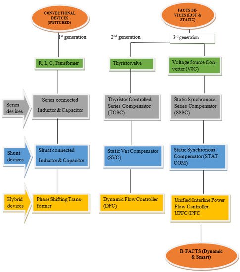
The first generation of FACTS devices were mechanically controlled capacitors, inductors, and phase-shifting transformers with mechanical on-load tap changers [1]. The second generation was developed such that thyristor valves replace the mechanical switches. This gave a significant improvement in the speed of the devices. The third generation was designed using voltage source converter (VSC) based devices [1]. These devices provide multiple and total control of the power system parameters [2]. To further extend the application of FACTS devices to a distribution network, there are custom power (CP) devices similar to FACTS devices, except that they are used only in distribution networks. An example is the distributed synchronous static compensators D-STATCOM [3]. The modification of FACTS to CP to be used in distributed networks can be considered as the foundation for the fourth generation of FACTS technologies. This advancement expands the application of FACTS controllers from being used only in transmission networks to deregulated CPPS networks.
2. Benefits of FACTS Technology in Power System
3. Classification of FACTS Controllers
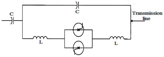
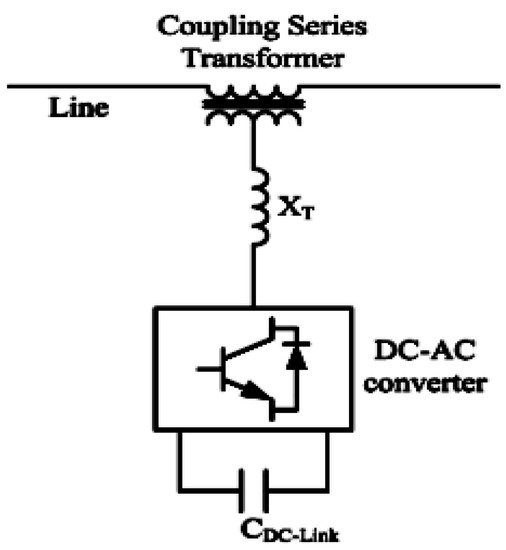
3.1. Series Controllers
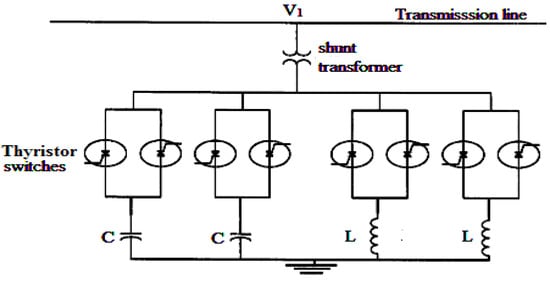
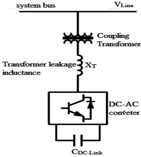
3.2. Shunt Controllers
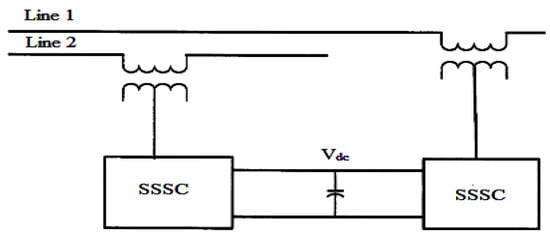
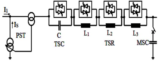
3.3. Combined Series-Series Controllers
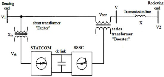
3.4. Combined Series-Shunt Controllers
3.5. The Merit of the Voltage Source Converter Based FACTS over Thyristor Controlled Devices
-
They consist of voltage source converters designed with an insulated-gate bipolar transistor or integrated gate-commutated thyristor, making them capable of controlling their output voltage;
-
With the voltage source converters, there is no risk of shunt or series resonant with the inductive line impedance that may initiate sub-synchronous oscillation;
-
They can control their output voltage over the whole VA rating independent of the AC system parameters;
-
They exchange controllable real power with AC system.
3.6. Distribution-FACTS Controllers
4. Research Trends Findings and Future Prospects
the result of a bibliometric analysis conducted using VOSviewer software with data extracted from Scopus shows an overlay visualization of keywords associated with FACTS devices and Cyber-Physical Power Systems (CPPS). The network of these keywords and their clusters reflect different directions of research trend in the application of FACTS devices.
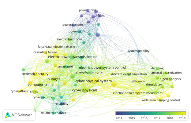
Figure 9. Overlay visualization showing research trend.
The following are key findings about the current application of FACTS devices and future utilization prospects.
- It is predicted that going into the future, say 2050, a very large amount of energy will be generated by RES while there will be a drastic reduction in fossil fuel power generation [31]. This implies that there will be more DGs penetration in power systems, bringing generation closer to distribution centers; hence D-FACTS will be more required than convectional FACTS devices. This is also considering the minimized advantage of D-FACTS devices over FACTS devices.
- CPPS of the future will be built with automated systems to include sensors, smart meters and communication systems to enable attributes such as self-control, self-optimizing and self-healing to guarantee autonomous power systems. Therefore, the future design of FACTS/D-FACTS devices must consider and appreciate interactions with the automated systems of CPPS to enhance effective integration. To this end, design modification of the operational configuration of FACTS/D-FACTS with sensors for real-time synchronized control and interaction with other CPPS technologies is an area that requires more research attention in the future.
- Cyberattack has been identified as the common most feared challenge of future CPPS as it has the potential of causing a total system breakdown and a worldwide blackout. Therefore, the new trend of research toward the use of D-FACTS in an MTD strategy against FDI must be expanded to improve power system security.
- In future, the advancement of optimal control capacity of FACT/D-FACT devices can be explored using cloud computing technology of the CPPS to store adequate data necessary to train the controllers with artificial intelligence required for dynamic control and protection of the system.
- Research and discussion about FACTS/D-FACTS have been extensive and stretch over a long time, but the main focus remained on their optimal location and operation. Extensive research on the actual cost of installing and operating FACTS/D-FACTS devices is limited in the literature. This area requires more detailed research to determine the exact economic implication of the use of FACTS/D-FACTS technologies. This has the potential to enhance proper power system planning in the future.
- Also, the real implementation or utilization of the FACTS/D-FACTS device is still very limited in several regions around the world. Countries that have them installed have only very few in their power grid. This low usage, especially in regions like Africa, is yet to be investigated. Few studies point towards limited production of these devices globally, but extensive research to ascertain the root cause leave room for further research.
- Since CPPS is consumer-centered, it will be interesting for demand-side management to be considered along with optimal placement and operation of DGs and D-FACTS devices in such a deregulated system. This possibly will enhance consumers' participation in microgrid planning and decision-making regarding power system infrastructure, especially considering economic implications.
This entry is adapted from the peer-reviewed paper 10.3390/su14137707
References
- Seifi, A.; Gholami, S.; Shabanpour, A. Power Flow Study and Comparison of FACTS: Series (SSSC), Shunt (STATCOM), and Shunt-Series (UPFC). Pacific. J. Sci. Technol. 2010, 11, 129–137.
- Hingorani, N.G.; Gyugyi, L. Understanding FACTS: Concepts and Technology of Flexible AC Transmission Systems; IEEE Press: Piscataway, NJ, USA; Wiley: New York, NY, USA, 2000; Volume 148, ISBN 0780334272.
- Sirjani, R.; Rezaee Jordehi, A. Optimal placement and sizing of distribution static compensator (D-STATCOM) in electric distribution networks: A review. Renew. Sustain. Energy Rev. 2017, 77, 688–694.
- Dawn, S.; Tiwari, P.K.; Goswami, A.K. An approach for long term economic operations of competitive power market by optimal combined scheduling of wind turbines and FACTS controllers. Energy 2019, 181, 709–723.
- Yu, Z.; Lusan, D. Optimal placement of FACTs devices in deregulated systems considering line losses. Int. J. Electr. Power Energy Syst. 2004, 26, 813–819.
- Rath, S.; Sahu, B.P.; Dash, P. Power system operation and control using FACT Devices. Int. J. Eng. Res. Technol. 2012, 1.
- Samimi, A.; Naderi, P. A New Method for Optimal Placement of TCSC Based on Sensitivity Analysis for Congestion Management. Smart Grid Renew. Energy 2012, 3, 10–16.
- Singh, S.; Pujan Jaiswal, S. Enhancement of ATC of micro grid by optimal placement of TCSC. Mater. Today Proc. 2019, 34, 787–792.
- Ersavas, C.; Karatepe, E. Optimum allocation of FACTS devices under load uncertainty based on penalty functions with genetic algorithm. Electr. Eng. 2017, 99, 73–84.
- Sharma, A.; Jain, S.K. Gravitational search assisted algorithm for TCSC placement for congestion control in deregulated power system. Electr. Power Syst. Res. 2019, 174, 105874.
- Mahdad, B.; Srairi, K. Application of a combined superconducting fault current limiter and STATCOM to enhancement of power system transient stability. Phys. C Supercond. Its Appl. 2013, 495, 160–168.
- Khan, I.; Mallick, M.A.; Rafi, M.; Mirza, M.S. Optimal placement of FACTS controller scheme for enhancement of power system security in Indian scenario. J. Electr. Syst. Inf. Technol. 2015, 2, 161–171.
- Tarafdar Hagh, M.; Alipour, M.; Teimourzadeh, S. Application of HGSO to security based optimal placement and parameter setting of UPFC. Energy Convers. Manag. 2014, 86, 873–885.
- Kang, T.; Yao, J.; Duong, T.; Yang, S.; Zhu, X. A hybrid approach for power system security enhancement via optimal installation of flexible ac transmission system (FACTS) devices. Energies 2017, 10, 1305.
- Sode-Yome, A.; Mithulananthan, N.; Lee, K.Y. Reactive Power Loss Sensitivity Approach in Placing FACTS Devices and UPFC; IFAC: New York, NY, USA, 2012; Volume 8.
- Lund, A.A.; Keerio, M.U.; Koondhar, M.A.; Jamali, M.I.; Tunio, A.Q. Investigation of advanced control for unified power flow controller (UPFC) to improve the performance of power system. J. Appl. Emerg. Sci. 2021, 11, 67.
- Magaji, N.; Mustafa, M.W. Optimal location and signal selection of UPFC device for damping oscillation. Int. J. Electr. Power Energy Syst. 2011, 33, 1031–1042.
- Singh, B.; Agrawal, G. Enhancement of voltage profile by incorporation of SVC in power system networks by using optimal load flow method in MATLAB/Simulink environments. Energy Rep. 2018, 4, 418–434.
- Bakir, H.; Kulaksiz, A.A. Modelling and voltage control of the solar-wind hybrid micro-grid with optimized STATCOM using GA and BFA. Eng. Sci. Technol. Int. J. 2020, 23, 576–584.
- Zhang, X.-P.; Rehtanz, C.; Bikash, P. Flexible AC Transmission Systems: Modelling and Control; Springer: Berlin/Heidelberg, Germany; New York, NY, USA; Dordrecht, The Netherlands; London, UK, 2012; Volume 148, ISBN 9783642282409.
- Das, D. Dynamic Control of Grid Power Flow Using Controllable Network Transformers; Georgia Institute of Technology: Atlanta, GA, USA, 2012.
- Krishna, S.B.C.V.; Sankar, K.S.; Haranath, P.V. Power System Operation and Control Using Fact Devices. In Proceedings of the 17th International Conference on Electricity Distribution, Barcelona, Spain, 12–15 May 2003; pp. 12–15.
- Sarkar, M. Load Flow Studies With UPFC Power Injection Model; National Institute of Technology Rourkela: Odisha, India, 2013.
- Gouda, P.K.; Sahoo, A.K.; Hota, P.K. Modeling and simulation of UPFC using PSCAD/EMTDC. Int. J. Phys. Sci. 2012, 7, 5965–5980.
- Farrag, M.E.E.A. Investigation of Advanced Control for the Unified Power Flow Controller (UPFC); University of Northumbria at Newcastle: Newcastle upon Tyne, UK, 2002.
- Pinheiro, G.G.; Henrique, C.; Guimar, B.P.B.; Gonzatti, R.B.; Pereira, R.R.; Cesar, W.; Ana, S.; Lambert-torres, G.; Santana-filho, J. Power Flow Control Using Series Voltage Source Converters in Distribution Grids. Energies 2022, 15, 3337.
- Hamidi, A.; Golshannavaz, S.; Nazarpour, D. D-FACTS cooperation in renewable integrated microgrids: A linear multi-objective approach. IEEE Trans. Sustain. Energy 2017, 10, 355–363.
- Shaheen, A.M.; Elsayed, A.M.; Ginidi, A.R.; Elattar, E.E.; El-Sehiemy, R.A. Effective Automation of Distribution Systems with Joint Integration of DGs/ SVCs Considering Reconfiguration Capability by Jellyfish Search Algorithm. Curr. Opin. Obstet. Gynecol. 2021, 9, 92053–92069.
- Shaheen, A.M.; Elsayed, A.M.; El-Sehiemy, R.A.; Ginidi, A.R.; Elattar, E. Optimal management of static volt-ampere-reactive devices and distributed generations with reconfiguration capability in active distribution networks. Int. Trans. Electr. Energy Syst. 2021, 31, e13126.
- Relic, F.; Maric, P.; Glavas, H.; Petrovic, I. Influence of FACTS device implementation on performance of distribution network with integrated renewable energy sources. Energies 2020, 13, 5516.
- Panda, D.K.; Das, S.; Smart grid architecture model for control, optimization and data analytics of future power networks with more renewable energy. Journal of Cleaner Production 2021, 301, 126877, doi: 10.1016/j.jclepro.2021.126877.