Your browser does not fully support modern features. Please upgrade for a smoother experience.
Please note this is an old version of this entry, which may differ significantly from the current revision.
Subjects:
Engineering, Manufacturing
Reinforcements of metal components are used in various applications, e.g., increasing the strength of forming tools in regions where high loads need to be carried, reducing the degradation of components, enhancing the fatigue life, and minimizing distortions. An extrusion tool is a typical application that requires reinforcements. The reinforcement enhances the tool life and erosion behavior of the tool and reduces elastic deformation.
- weld cladding
- residual stresses
- reinforcement
- Additive manufacturing
- WAAM
- Welding
- compression
- Simulation
- LS-Dyna
1. Extrusion Tool
Extrusion processes are known for their high dimensional accuracy and good surface quality [2]. The increased production rate makes this process cost-effective [3]. In metal extrusion, the forming forces are applied to one end of the tool, while the formed component is obtained either at the opposite end (forward extrusion) or the same end (reverse extrusion) [4]. In another form of extrusion known as double cup extrusion, the billet is squeezed into the desired shape between the two punches [5]. The movable upper punch is pushed towards the fixed lower punch, and the pressure is applied to the billet, resulting in the free flow of the material around the two punches [5,6]. A double cup extrusion model is shown in Figure 1.
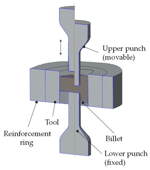
Many Additive Manufacturing (AM) techniques are associated with the extrusion process, such as liquid metal AM, in which the material is melted before extrusion and solidified after cooling [7]. According to ASTM F42 [8], Fused Deposition Modeling (FDM) is also known as material extrusion AM. Nowadays, AM technology is also employed for extrusion-based printing methods, such as Selective Laser Melting (SLM), to produce extrusion tools of diverse materials that would otherwise be difficult to manufacture due to high operating temperatures [9]. As extrusion involves very high pressure, it causes the formation of high tensile stresses in the tool, which can lead to crack formation [10,11]. Tensile stresses develop on the inner side of the tool and limit its load capacity. A reinforcement ring (see Figure 1) is usually used around the tool to increase its strength. The reinforcement ring compensates for tensile stresses and provides the tool with additional strength [12]. Lange [13] reported that using a steel reinforcement ring around the extrusion tool raises the permissible internal pressure of the tool to 1390 MPa. Thus, by adding a single reinforcement ring around the tool, the internal pressure-bearing capacity of the tool can be increased up to 80% relative to the tool without a reinforcement ring. Klocke et al. [12] stated that extrusion dies without reinforcement rings lose 37.5% of their strength during extrusion. Placing two reinforcement rings next to each other enhances the internal pressure bearing capacity of the extrusion tool by 27% [12]. Therefore, to increase the strength of the extrusion tools, either the undesired tensile stresses should be minimized, or reinforcement should be applied [11].
2. Reinforcement of Toolings
Numerous metal components are reinforced by applying external pressure on them by various techniques. The press-fit or thermal shrink-fit method has been used to generate compressive stresses on the cylindrical components to reinforce them [14].
A commonly used industrial approach for reinforcing a cylindrical rod using the shrinkage of a hot ring is presented in Figure 2. In this process, the metal ring is heated to a defined temperature, such as 1000 °C [15], followed by mounting on the cylindrical rod and left to cool. The heating causes the thermal expansion of the metal ring and its diameter increases. When the ring cools off, the thermal contraction of the metal develops compressive stresses on the rod due to the close fit between the rod and the ring. These compressive stresses increase the strength and enhance the fatigue life of the metal rod [16].
The method mentioned above for reinforcing the components is very effective and cheap, but it has some disadvantages. Since it requires a tight tolerance between the shaft and the bore (interference fit P7/h6 [17] according to ANSI B4.2 [18]), positioning of the hot ring must be done with advanced tools, such as hydraulic presses, mounting levers and mounting clamps [19].
Although shrink fitting is used to enhance the fatigue life of the components [20], the most significant disadvantage of shrink fitting is that it can only be used on cylindrical components [21]. On the other hand, the hot ring can damage the rod if it dislocates from its axis or if the compressive stresses applied to the ring increase the tensile strength [22]. This method could also significantly change the stress and strain profile and generate considerable tensile stresses on the surface [23]. It may initiate cracks that propagate and eventually lead to specimen failure [14,24]. Shrink-fit requires exact fittings between the adjacent surfaces, leading to complications when dealing with larger components [20].
In addition, to shrink fitting, other techniques, such as thermal autofrettage, mechanical autofrettage, explosives, and part rotation can reinforce the components. The autofrettage process generates a very high pressure within the tube cavity, inducing compressive residual stresses after the pressure is released [25]. According to Thumser et al. [26], the thermal autofrettage of a round, symmetrical part increases its endurance limit and reduces the amount of tensile residual stresses, particularly from the internal surface. Jahromi et al. [27] claimed that the autofrettage of a metal tube with reinforced ceramic particles on its inner surface increases the amount of compressive residual stress. Shufen et al. [28] proposed that locally heating a 1080-steel tube to an elevated temperature using thermal autofrettage followed by its cooling induces compressive stresses at its inner surface. They reported that the development of the compressive residual stresses during cooling increases the fatigue performance of the tube. Kamal et al. [29] imposed high pressure on the inner surface of an SS304 steel tube using thermal autofrettage, which after cooling, developed compressive residual stresses on its surface. They found that the load-carrying capacity and the fatigue strength of the tube enhanced due to compressive stresses. Besides thermal autofrettage, Malik et el. [30] used a mechanical autofrettage method to compress a thick steel cylinder using a conical mandrel. This method develops compressive stresses in the cylinder and strengthens it. Kaplan et al. [31] used an explosive method to reinforce the thick-walled forging dies made of steel and aluminium. They used high-pressure explosive energy in a controlled way to establish plastic flow on the surface of the die-cavity. With the reduction of the pressure from the die, high residual stresses are generated. Zare et al. [32] utilized a rotational method to strengthen a thick-walled cylinder. They rotated the cylinder with a high angular velocity, which developed compressive residual stresses and resulted in its reinforcement. Although the procedure mentioned above offers reinforcement, they primarily create compressive stresses on the internal cavity of the cylindrical specimen. They may also significantly increase the harmful tensile stresses on the cylinder’s exterior surface, leading to cracking [33].
Some other conventional methods to strengthen the components include grain boundary strengthening [34], solid solution strengthening [35], heat treatment [36], precipitation hardening [37], and cold working [38]. Apart from these conventional surface hardening techniques, weld cladding, in which a metal is welded/coated with a layer of another or the same metal, is also an effective method to minimize the tensile residual stresses, hence, improving the mechanical properties of components (up to 3 mm or more) [39]. In the past, various metals have been used as a coating/clad to achieve the desired properties, i.e., nickel, steel alloys, copper alloys, manganese alloys, and composites [40]. Since it is known that welding causes residual stresses, various researchers have sought to minimize the stresses by weld cladding. Pan et al. [41] coated the high strength steel grade 16 Mn on the surface of steel grade 9Cr to enhance the hardness and reduce the residual stresses and corresponding wear and crack propagation. Jiang et al. [42] reported that high thermal loads during cladding create tensile stresses, which might cause cracks and weaken the material. They suggested increasing the number of clad layers on the metal surface to reduce tensile residual stresses. However, they did not mention the optimized number of layers and their pattern. Benghalia et al. [43] used the weld-cladding process on a cylindrical substrate to strengthen it. They revealed that weld-cladding develops more compressive stresses on the substrate than the typical shrink-fit joint. The compression reduces the pre-existing tensile residual stresses on the substrate and enhances the compressive stresses, increasing its strength.
Numerical techniques are becoming an essential tool for estimating temperature, distortion, and residual stresses caused by the welding processes. Several simulation techniques have been presented to compute the thermal behavior during the cladding process in recent years. Weld-cladding simulations are typically performed by thermo-mechanical simulation methods, which predict the global thermo-mechanical behavior of the weld. Incorporating thermal material parameters into the model at the melting point and room temperature simplifies this behavior [44]. Lou et al. [45] developed a three-dimensional finite element model to examine the influence of a heat source on a heat-affected zone. They also observed the effect of the cooling rate on the cladding layer. Gao et al. [46] developed a 3D thermal FEM (Finite Element Method) model to simulate the temperature field in the Fe-based weld cladding. They evaluated different process parameters, i.e., temperature distributions, cooling rate, and solidification rate. Kumar et al. [47] developed a 3D model to estimate various physical phenomena, i.e., heat transfer, fluid flow, and convection during the cladding process. They observed that changing the scanning speed changes the area of the weld pool and the degree of convection. Hosseini et al. [48] revealed that heat input, welding sequence, and substrate geometry influence the thermal cycle and stress state in the wire arc welding processes. Smith et al. [49] evaluated the welding of a single clad layer using more than 40 finite element simulations to assess the influence of different process variables on the expected residual stresses. They observed that the hardening modulus of the material has a significant influence on the developed stresses. However, mesh size, welding efficiency, and thermal boundary conditions are less influential. Karlsson et al. [50] and Lindgren [51] analyzed the effect of different variables involved in the simulations on residual stresses, heat input, and deformation. They found that the material’s heat capacity is one of the parameters that could affect the temperature distribution and resulting stresses. Feroozmehr et al. [52] utilized a finite element approach to investigate the influence of weld deposition patterns on the temperature and stress distribution during the cladding process. However, the weld bead dimensions and the deposition pattern that could generate the maximum compressive stresses on the specimen have not been explained.
From state of the art, it can be concluded that various methods have been used to enhance the strength of the components by cladding. However, no previous study could be found on weld cladding induced targeted residual stresses in a tool. Moreover, there is no information on how multiple clad layers should be welded to maximize the compressive stresses on the component’s surface, where operating stresses are usually the highest. Topics requiring further investigation include: the effect of the number of clad layers, the number of beads in a layer, the size of the beads, the distance between the different layers, and the effect of cavities on the developed stresses. In the present study, weld cladding is introduced to induce compressive stresses in a cylindrical tool in a controlled manner.
This entry is adapted from the peer-reviewed paper 10.3390/met12060984
This entry is offline, you can click here to edit this entry!