Your browser does not fully support modern features. Please upgrade for a smoother experience.
Please note this is an old version of this entry, which may differ significantly from the current revision.
Actuators and sensing elements are vital components of MEMS resonators. For coupled BAW resonators, capacitive actuation and sensing elements, piezoresistive sensing elements, and piezoelectric actuation and sensing elements are commonly adopted.
- bulk acoustic wave (BAW)
- coupled resonators
- transduction methods
1. Capacitive Actuation and Sensing
Parallel plates like comb fingers are normally utilized to implement the capacitive actuation [1][2][3][4][5][6]. In the capacitive actuation, two parallel plates are loaded with an actuation voltage to form an electric field and generate an electrostatic force.
In terms of capacitive sensing [4][5][6], the displacement of the moving plate causes a change in the capacitance, leading to the charge flow of the capacitor, resulting in a motional current.
Capacitive transduction is a popular method for actuation and sensing of a MEMS device due to its low-cost and flexible design, simplicity of fabrication and implementation, and the capability to integrate with interface electronics systems [7][8][9]. However, it also has some drawbacks such as nonlinearity [6], pull-in instability [10], and an AC force that could appear at the double frequency, the feedthrough signal (Table 1).
Table 1. Description of several classic transduction mechanisms applied to coupled BAW MEMS resonators.
| Transduction Methods | Capacitive Actuation and Sensing | Piezoresistive Sensing | Piezoelectric Actuation and Sensing |
|---|---|---|---|
| Actuation force (F) |
F≈(12V2d+2|Vac|Vd)dCdx [7] |
Not applicable yet | F=e33A3Vach− Longitudinal F=e31A1Vach- Transverse [8] |
| Sensed motional current (imot) | imot=Vd∂C∂x∂x∂t [7] |
imot≈VdR(ΔRrRr) [11] |
|imot|=|ω⋅e33A3S3| Longitudinal |imot|=|ω⋅e31A3S1| Transverse [8] |
| Cons | Parasitic capacitance; Nonlinearity; complex circuit design; thin film damping; limitation in liquids [12] | Temperature dependency; high power consumption with using high DC voltages; noisy |
Processing difficulty in piezoelectric materials; not possible static measurement |
| Pros | Low power consumption; good noise performance; easy to fabricate | Simple setup; inherent shielding; applicable to liquids [13] |
Eliminating frequency drifts caused by DC voltage variations due to no DC voltages needed here [14]; Applicable to liquids [15][16][17][18] |
1.1. One-Port Configuration
In the one-port configuration [11] as shown in Figure 1, each resonator has four capacitive electrodes all serving as actuation electrodes, and the motional current is picked up from the anchors of the resonators. For the one-port configuration, the motional current can be increased by increasing the electrode overlap area and decreasing the gap between the electrode and the resonator body. However, the feedthrough current [19][20][21] can also be increased by shrinking the gap.
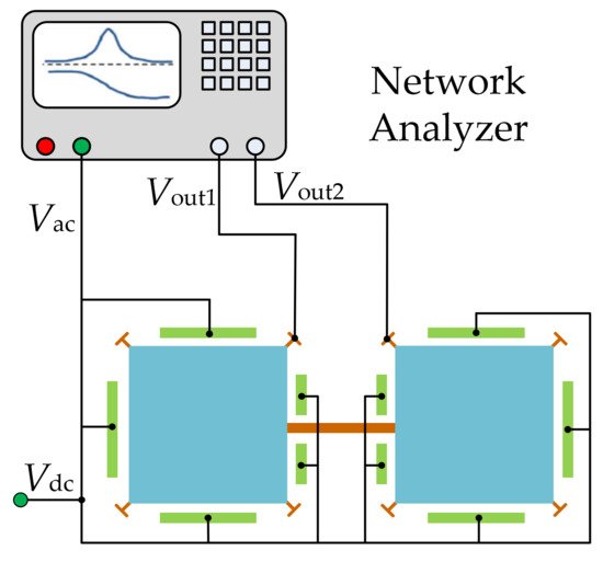
Figure 1. Schematic of a one-port configuration for a 2-DoF square-plate BAW resonator.
1.2. Two-Port Configuration
As illustrated in Figure 2, in a two-port configuration [11][21], each resonator has one group of electrodes for actuation and the other group of electrodes for sensing. Compared to the one-port configuration, under the same actuation voltage, the actuation force decreases but the feedthrough signal decreases in the two-port configuration as the sensing and driving electrodes are separated and cross-talk capacitance is reduced.
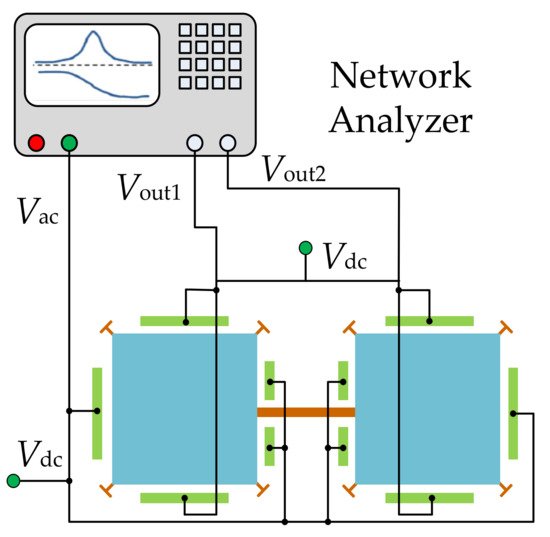
Figure 2. Schematic of a two-port configuration for a 2-DoF square-plate resonator system.
2. Capacitive Actuation and Piezoresisitive Sensing
The piezoresistive effect can occur in all materials, which refers to the change of resistance resulting from mechanical stress. This effect has been applied to many commercial devices such as pressure sensors and accelerometers [1]. For the pressure sensor, integrated piezo resistors are used to measure the deformation of the pressure-sensing membrane. For the piezoresistive accelerometer, the resistance of piezo resistors embedded in the supporting springs changes with the stress variation due to the input acceleration, which is utilized to measure the input acceleration. The resistance measurement is also easy to be implemented and the piezo resistors are inherently shielded structures, which make it feasible and popular for the application of microsensors. As shown in Figure 3, a DC voltage (Vd) is applied to the resonator at the anchors to detect the change of resistance, and then the motional current can be obtained [22][23].
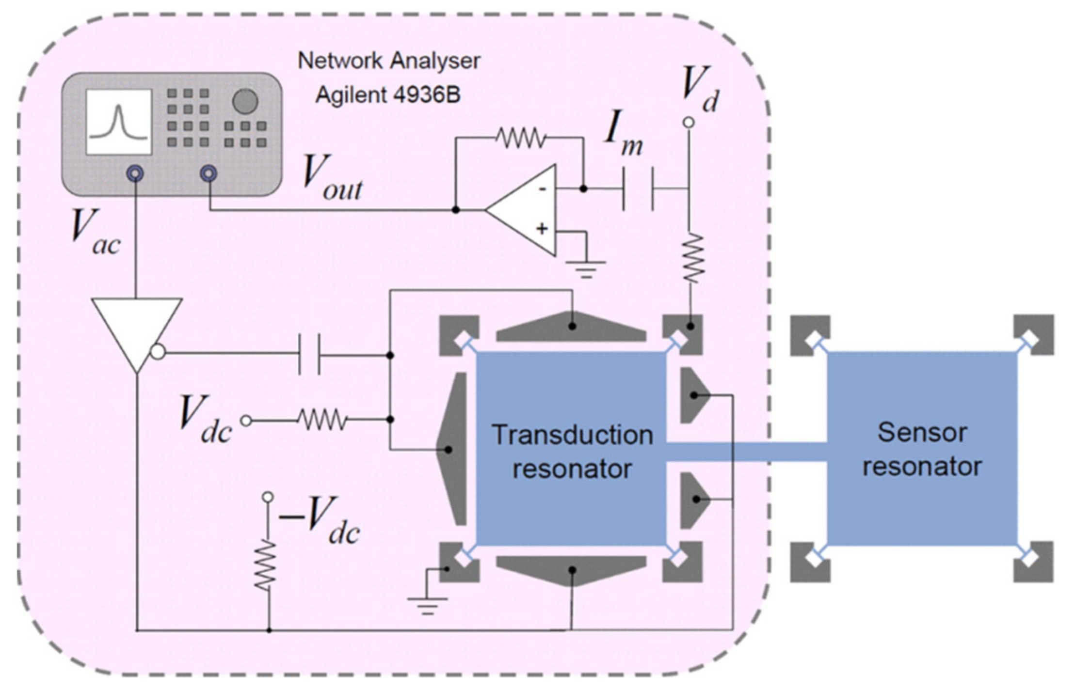
Figure 3. Measurement setup for a coupled BAW resonator system using capacitive actuation and piezoresistive sensing.
In piezoresistive sensing configurations [24][25][26][27][28], all surrounding electrodes can be used for capacitive actuation because the motional current is picked up from the body of the resonator. Besides this, the motion signal can be increased by tuning Vd rather than shrinking the transduction gap or increasing the applied actuation voltage, but it is limited to the piezoresistive coefficient of the single crystal silicon and the dissipation of the electric power of the resonator.
For BAW resonators vibrating at the extensional mode, the motional current is larger with the piezoresistive sensing configuration than with the capacitive sensing configuration [11]. Figure 18 shows the frequency responses for a square-plate BAW resonator operated in the extensional mode with different sensing methods but the same actuation. In contrast to the device with capacitive sensing, the device with piezoresistive sensing improves the output signal from 0.02 dB to 0.5 dB, and the signal distortion caused by the feedthrough signal is eliminated [22][23].
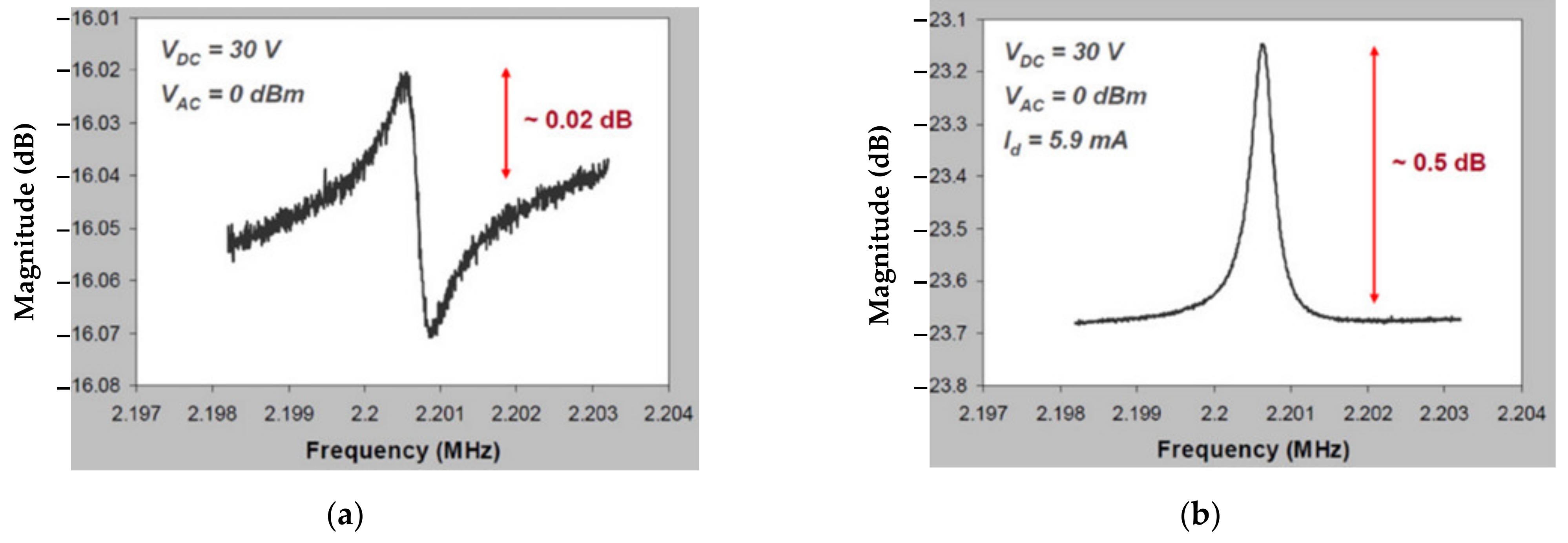
Figure 4. The frequency response measured for a BAW resonator with square extensional (SE) mode in the air. (a) One-port capacitive actuation and sensing method; (b) One-port capacitive actuation and piezoresistive sensing method.
In another study, Iqbal et al. investigated the 2-DoF and 3-DoF square-plate and 2-DoF disk BAW resonators in the extensional mode [29][30]. In this work, the total output current was enhanced by summing the currents of all resonators and the piezoresistive and capacitive sensing methods were both adopted to be compared with each other. In [30], the insertion loss and the Q factor of a 2-DoF resonator using the piezoresistive sensing were compared with that of a 1-DoF resonator using capacitive sensing. There was a 10 dB reduction in the insertion loss and an increase of 3400 in the Q factor for the device using piezoresistive sensing proposed in [30]. Therefore, the results show that with the piezoresistive sensing configuration (shown in Figure 5 and Figure 6), the overall transduction efficiency was improved, thereby obtaining a higher Q factor.
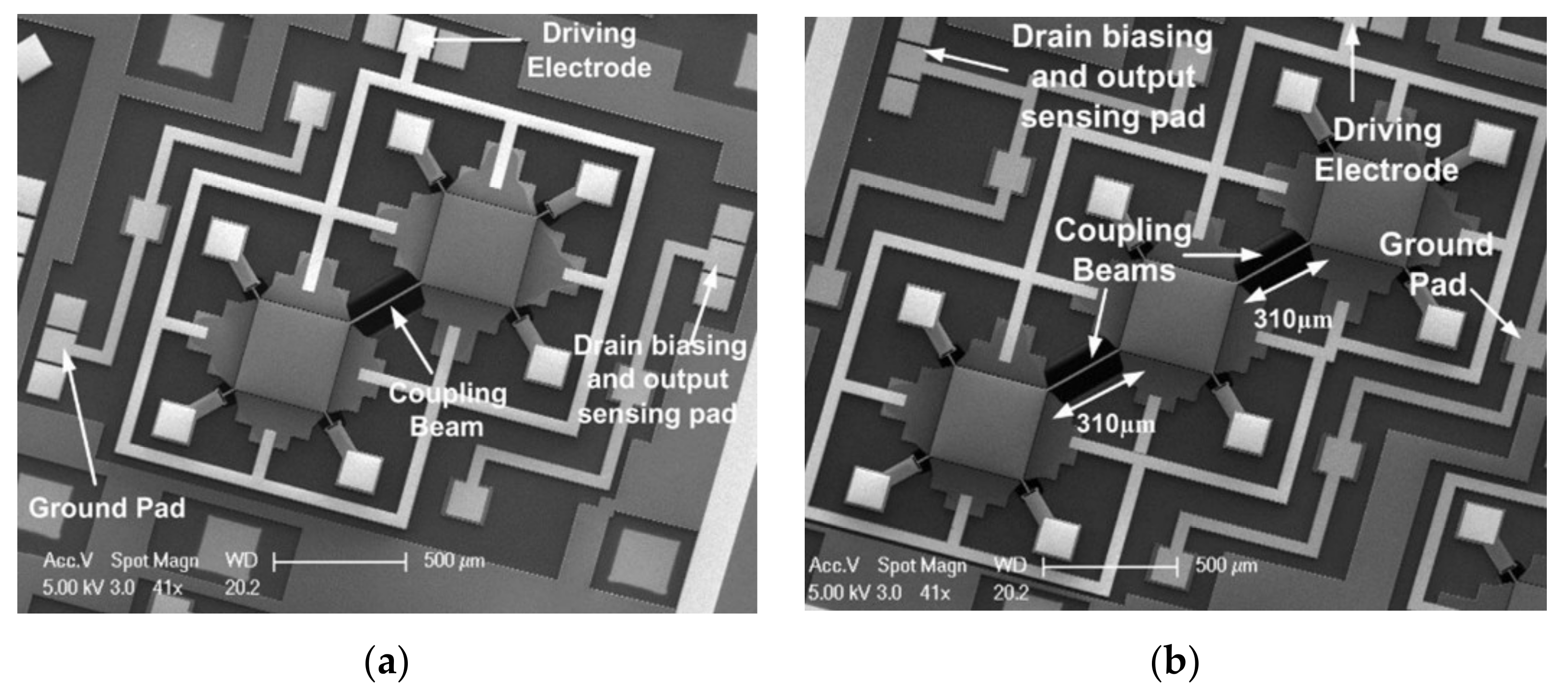
Figure 5. SEM image of the fabricated BAW rectangular-plate resonators with capacitive actuation and piezoresistive sensing setup. (a) A 2-DoF coupled BAW resonator device; (b) A 3-DoF coupled BAW resonator device.
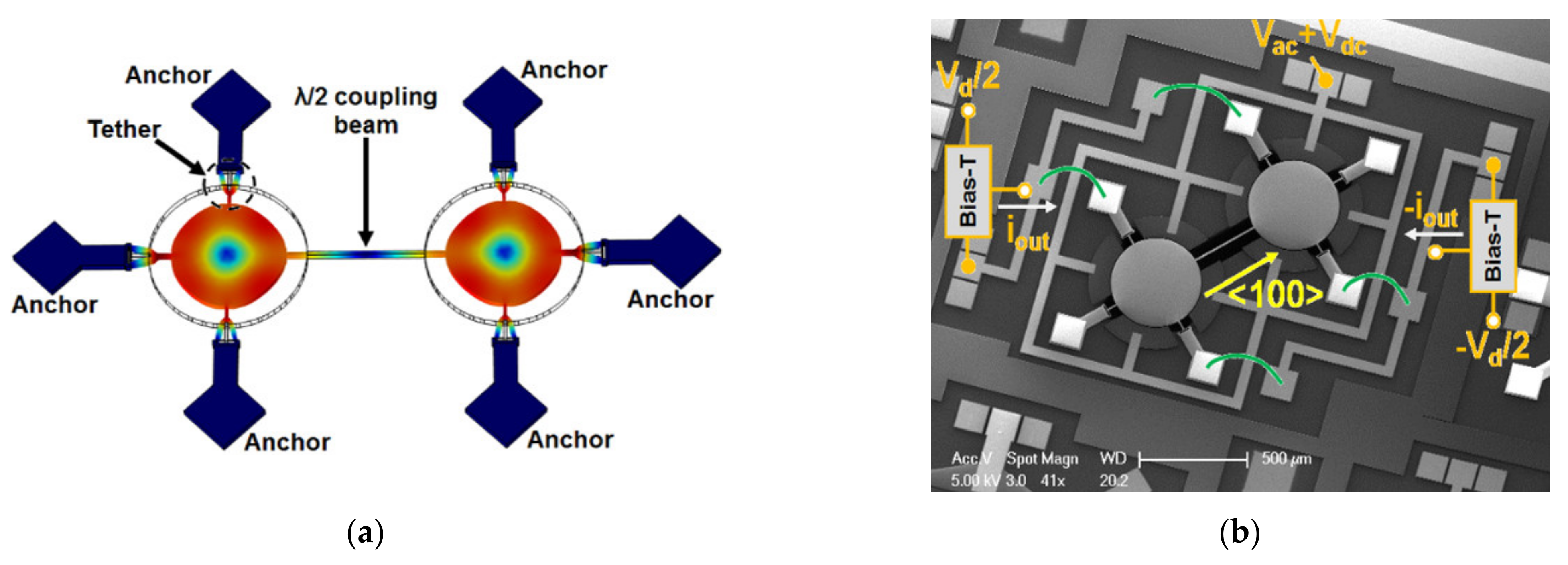
Figure 6. (a) FEM simulation of 2-DoF BAW disk resonators with in-phase extensional mode shown; (b) SEM image of the fabricated 2-DoF BAW disk resonators with capacitive actuation and piezoresistive sensing.
3. Piezoelectric Actuation and Piezoelectric Sensing
The piezoelectric effect refers to the ability of certain materials which can generate the electric charge in response to the applied mechanical stress and vice versa (mechanical stress can result from an applied electrical field) [1]. There are two common piezoelectric transduction configurations [1][8]: the longitudinal configuration (shown in Figure 21a), where the force (F) is in the direction of the electric field (ε3), and the transverse actuation configuration (see Figure 7b), where the force (F) is perpendicular to the applied electric field (ε3). The electrodes (marked in grey in Figure 21) on the top and bottom surface of the piezoelectric material form a capacitor and the current through the capacitor will have a piezoelectric component in addition to the regular capacitance current.

Figure 7. Piezoelectric transduction configuration. (a) Longitudinal configuration; (b) Transverse configuration. Note: t is the thickness of the piezoelectric layer, A1 is the cross-sectional area of the piezoelectric layer, A3 is the electrode area, ε3 is the intensity of the electric field, and F is the generated force.
The commonly used piezoelectric materials are PZT, ZnO, and AlN. Among these three materials, PZT has the highest piezoelectric coefficient but the lowest acoustic velocity which will result in more inner mechanical energy loss, thereby deducting the Q factor [12]. ZnO is chemically unstable, and this will lead to non-consistent measurement results. AlN has a lower piezoelectric coefficient but the highest acoustic energy, so there will be less inner mechanical loss [12]. The AlN thin film is insulated. Moreover, the compatibility with CMOS of AlN also makes it potentially applicable to chip-level integration [12]. The devices presented below are all fabricated using AlN as the piezoelectric material.
As an example, Chellasivalingam et al. designed two identical square-plate resonators weakly coupled by a short beam, and resonators were operated at the WG mode [31][32], as shown in Figure 8. The reverse piezoelectric effect was used for the actuation of the resonator while the piezoelectric effect was used for the pick-up of the motion. The piezoelectrically induced strain was converted back to an electrical output voltage. The mode localization was adopted in the weakly coupled BAW resonators to characterize its mass sensitivity. The normalized sensitivity based on the AR was 148.22, and the Q factor of 1773.8 was achieved in a vacuum. The fabrication of these two devices followed the PiezoMUMPs process [33]. The silicon device layer was directly utilized as the ground layer, then a sputtered AlN film on the Si layer served as the piezoelectric layer. Finally, a thin film of Al was deposited on the AlN layer as the top electrode, and thus the thin-film piezoelectric-on-silicon resonator (TPOS) was developed [34][35][36].
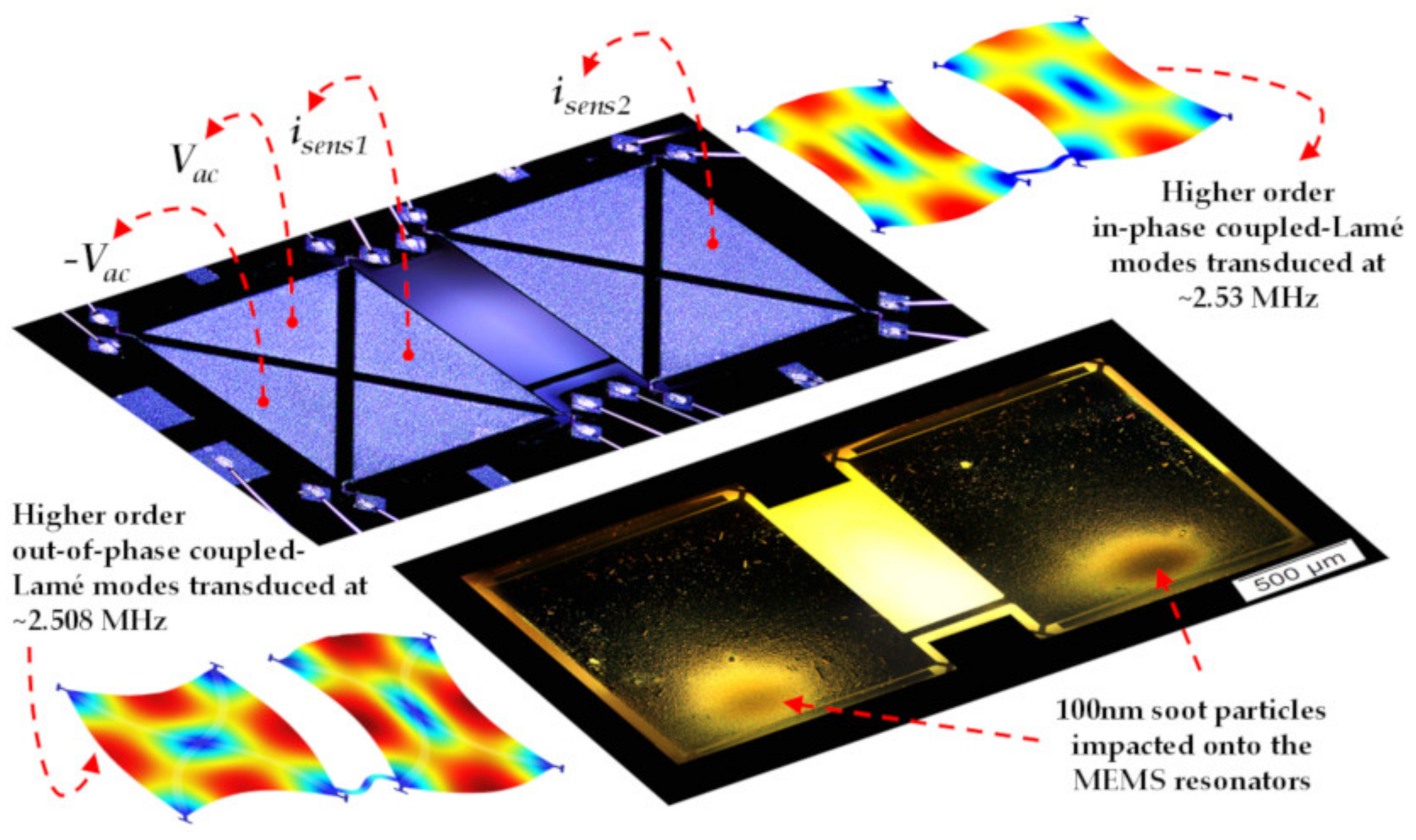
Figure 8. Schematic of the piezoelectric transduction mechanism applied to a 2-DoF weakly coupled BAW square-plate resonator device vibrating at in-phase and out-of-phase WG modes. The mass perturbation is conducted by applying particles onto the bottom surface of the resonators.
As piezoelectric resonant devices like FBARs exhibit high electromechanical coupling efficiencies without DC voltages, there will be a low signal transmission loss, thereby achieving a relatively small motional resistance, which is beneficial to the design of the setup for the measurement. Additionally, the DC voltage is not required for the operation of piezoelectric devices, which makes it more suitable for resonators operated in liquids than resonators with capacitive transduction. This is due to the DC voltage used for capacitive transduction in liquid being limited to several volts to avoid the electrolysis phenomenon in liquid. The electrolysis phenomenon will lead to a low transduction factor for capacitive sensing.
Therefore, combined with the advantages of the piezoelectric transduction and in-plane vibration modes, weakly coupled BAW resonators exhibit a high potential to be applied as sensors for chemical and biological applications. So far, the coupled BAW resonators based on mode localization have not been explored extensively.
4. Capacitive-Piezo Transduction
For the piezoelectric resonators shown in Figure 9a, both the top and bottom electrodes are directly in contact with the piezoelectric layer, and the interfacial strain loss normally occurs in the interface between the electrode and piezoelectric layers [1][8][32][37]. For the capacitive resonators indicated in Figure 9b, the transduction gaps are designed to separate the resonator body and electrodes, so there will be no interfacial strain loss [1][2][3][4][5][6]. Combining the main features of piezoelectric and capacitive resonators, a capacitive-piezo transduction configuration [28] where a resonator made of pure piezoelectric material (AlN) is separated from the electrodes by a small transduction gap is developed, as shown in Figure 9c. The piezoelectric component is used for achieving high coupling, and the non-contacting capacitive transduction component is used for achieving a high Q factor [28].
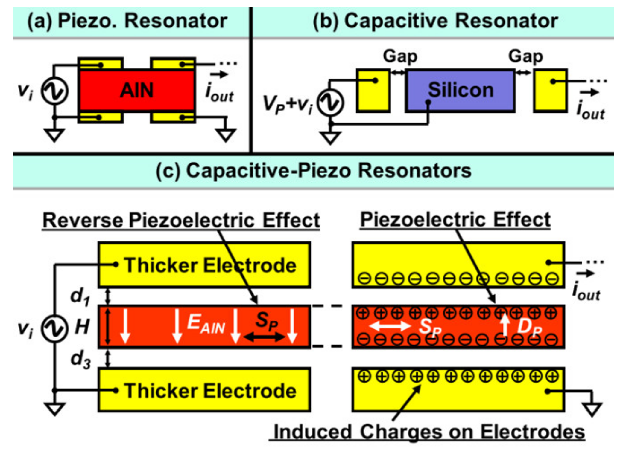
Figure 9. Working principle of a conventional piezoelectric resonator, capacitive resonator and novel capacitive-piezo resonator.
Figure 10 shows a 1-DoF and 2-DoF capacitive-piezo BAW disk resonant device with different working modes and anchors. In these two devices, a small transduction gap is designed to reduce the strain loss from the resonator body to the electrode and to eliminate the energy loss from the metal layer-to-piezoelectric layer interface. This gap should be small enough to make full use of the strong electromechanical coupling efficiency of the piezoelectric transduction, so a nano-scale gap is adopted here. For the 1-DoF resonator device developed by Robert et al. [38], a new self-switching resonator was achieved with a high Q of 9000 at 300 MHz enabling the device to act as a switchable AlN filter for RF front ends. Another study based on the 2-DoF resonator device [39], showed a higher Q factor of 12,748 which is more than 2.2 times higher than that of the conventional piezoelectric resonators with contacting electrodes.

Figure 10. (a) Schematic of a 1-DoF capacitive-piezo disk resonator operated at the radial contour mode with the anchor at the center; (b) Schematic of a 2-DoF capacitive-piezo disk resonator device operated at the WG mode with the anchor connected to the resonator body by a suspension beam.
This entry is adapted from the peer-reviewed paper 10.3390/s22103857
References
- Chollet, F.; Liu, H. A (not so) Short Introduction to Micro Electromechanical Systems, MEMS Encyclopedia. 2015. Available online: https://memscyclopedia.org/introMEMS.html (accessed on 1 April 2015).
- Lee, J.E.-Y.; Bahreyni, B.; Seshia, A. An Axial Strain Modulated Double-Ended Tuning Fork Electrometer. Sens. Actuators A Phys. 2008, 148, 395–400.
- Nguyen, C.T.-C.; Howe, R.T. An Integrated CMOS Micromechanical Resonator High-Q Oscillator. IEEE J. Solid-State Circuits 1999, 34, 440–455.
- Verd, J.; Uranga, A.; Abadal, G.; Teva, J.; Torres, F.; Pérez-Murano, F.; Fraxedas, J.; Esteve, J.; Barniol, N. Monolithic Mass Sensor Fabricated Using a Conventional Technology with Attogram Resolution in Air Conditions. Appl. Phys. Lett. 2007, 91, 13501.
- Blanc, N.; Brugger, J.; de Rooij, N.F.; Dürig, U. Scanning Force Microscopy in the Dynamic Mode Using Microfabricated Capacitive Sensors. J. Vac. Sci. Technol. B Microelectron. Nanom. Struct. Process. Meas. Phenom. 1996, 14, 901–905.
- Bai, Y.; Lu, Y.; Hu, P.; Wang, G.; Xu, J.; Zeng, T.; Li, Z.; Zhang, Z.; Tan, J. Absolute Position Sensing Based on a Robust Differential Capacitive Sensor with a Grounded Shield Window. Sensors 2016, 16, 680.
- Wang, Y. Mems Multi-Dof Weakly Coupled Resonator Based on Mode Localization for Mass Change Sensing Applications. Ph.D. Thesis, Université de Liège, Liège, Belgium, 2019.
- Kaajakari, V. Practical MEMS, 1st ed.; Small Gear Pub.: Las Vegas, NV, USA, 2009.
- Kaajakari, V.; Mattila, T.; Oja, A.; Seppa, H. Nonlinear Limits for Single-Crystal Silicon Microresonators. J. Microelectromech. Syst. 2004, 13, 715–724.
- Seeger, J.I.; Boser, B.E. Charge Control of Parallel-Plate, Electrostatic Actuators and the Tip-in Instability. J. Microelectromech. Syst. 2003, 12, 656–671.
- Lin, A.-H.; Lee, J.-Y.; Yan, J.; Seshia, A.A. Methods for Enhanced Electrical Transduction and Characterization of Micromechanical Resonators. Sens. Actuators A Phys. 2010, 158, 263–272.
- Ali, A. Electrical Characterization of Piezoelectric MEMS Resonators in Liquid Phase for Sensing Applications. Ph.D. Thesis, City University of Hong Kong, Hong Kong, China, 2018.
- Rahafrooz, A.; Pourkamali, S. Rotational Mode Disk Resonators for High-Q Operation in Liquid. In Proceedings of the SENSORS, 2010 IEEE, Waikoloa, HI, USA, 1–4 November 2010; pp. 1071–1074.
- Wu, G.; Xu, J.; Ng, E.; Chen, W. MEMS Resonators for Frequency Reference and Timing Applications. J. Microelectromech. Syst. 2020, 29, 1137–1166.
- Begum, H.; Qian, J.; Lee, J.E.-Y. Effect of Crystal Orientation on Liquid Phase Performance of Piezoelectric-on-Silicon Elliptical Plate Resonators. Sens. Actuators A Phys. 2022, 340, 113548.
- Qian, J.; Begum, H.; Lee, J.E.-Y. Acoustic Centrifugation Facilitating Particle Sensing in Liquid on a Piezoelectric Resonator. IEEE Electron Device Lett. 2022, 43, 801–804.
- Begum, H.; Qian, J.; Lee, J.E.Y. Fully Differential Higher Order Transverse Mode Piezoelectric Membrane Resonators for Enhanced Liquid-Phase Quality Factors. J. Micromechan. Microeng. 2021, 31, 104004.
- Begum, H.; Qian, J.; Lee, J.E.-Y. Piezoelectric Elliptical Plate Micromechanical Resonator with Low Motional Resistance for Resonant Sensing in Liquid. IEEE Sens. J. 2021, 21, 7339–7347.
- Puers, B.; Peeters, E.; Van Den Bossche, A.; Sansen, W. A Capacitive Pressure Sensor with Low Impedance Output and Active Suppression of Parasitic Effects. Sens. Actuators A Phys. 1990, 21, 108–114.
- Lee, J.E.-Y.; Seshia, A. Parasitic Feedthrough Cancellation Techniques for Enhanced Electrical Characterization of Electrostatic Microresonators. Sens. Actuators A Phys. 2009, 156, 36–42.
- Xu, Y.; Lee, J.E.-Y. Single-Device and On-Chip Feedthrough Cancellation for Hybrid MEMS Resonators. IEEE Trans. Ind. Electron. 2012, 59, 4930–4937.
- Lin, A.; Yan, J.; Seshia, A. Mechanically Coupled Bulk-Mode Dual Resonator Mass Sensor. Procedia Eng. 2010, 5, 1454–1457.
- Lin, A.T.-H.; Yan, J.; Seshia, A.A. Electrically Addressed Dual Resonator Sensing Platform for Biochemical Detection. J. Microelectromech. Syst. 2012, 21, 34–43.
- Wei, X.; Seshia, A.A. Differential Piezoresistive Sensing in a Bulk-Mode Micromechanical Resonator. Micro Nano Lett. 2013, 8, 107–110.
- Qaradaghi, V.; Ramezany, A.; Babu, S.; Lee, J.B.; Pourkamali, S. Nanoelectromechanical Disk Resonators as Highly Sensitive Mass Sensors. IEEE Electron Device Lett. 2018, 39, 1744–1747.
- Harley, J.A.; Kenny, T.W. A High-Stiffness Axial Resonant Probe for Atomic Force Microscopy. J. Microelectromech. Syst. 2001, 10, 434–441.
- Minne, S.C.; Manalis, S.R.; Quate, C.F. Parallel Atomic Force Microscopy Using Cantilevers with Integrated Piezoresistive Sensors and Integrated Piezoelectric Actuators. Appl. Phys. Lett. 1995, 67, 3918–3920.
- Tu, C.; Zhu, H.; Xu, Y.; Lee, J.E.-Y. Differential-Capacitive-Input and Differential-Piezoresistive-Output Enhanced Transduction of a Silicon Bulk-Mode Microelectromechanical Resonator. Sens. Actuators A Phys. 2014, 210, 41–50.
- Iqbal, A.; Lee, J.E.-Y. Piezoresistive Sensing in a SOI Mechanically Coupled Micromechanical Multiple-Resonator Array. IEEE Trans. Electron Devices 2012, 59, 3091–3096.
- Iqbal, A.; Zhang, W.; Lee, J.E.-Y. Enhanced Piezoresistive Sensing via Synchronized Oscillations in a Mechanically Coupled Disk Array. In Proceedings of the 2013 Transducers Eurosensors XXVII: The 17th International Conference on Solid-State Sensors, Actuators and Microsystems (TRANSDUCERS EUROSENSORS XXVII), Barcelona, Spain, 16–20 June 2013; pp. 1384–1387.
- Chellasivalingam, M.; Pandit, M.; Kalberer, M.; Seshia, A.A. Ultra-Fine Particulate Detection Using Mode-Localized MEMS Resonators. In Proceedings of the 2019 Joint Conference of the IEEE International Frequency Control Symposium and European Frequency and Time Forum (EFTF/IFC), Orlando, FL, USA, 14–18 April 2019; pp. 1–5.
- Chellasivalingam, M.; Imran, H.; Pandit, M.; Boies, A.M.; Seshia, A.A. Weakly Coupled Piezoelectric MEMS Resonators for Aerosol Sensing. Sensors 2020, 20, 3162.
- Cowen, A.; Hames, G.; Glukh, K.; Hardy, B. PiezoMUMPs Design Handbook; MEMSCAP Inc.: Durham, NC, USA, 2014.
- Ho, G.K.; Abdolvand, R.; Sivapurapu, A.; Humad, S.; Ayazi, F. Piezoelectric-on-Silicon Lateral Bulk Acoustic Wave Micromechanical Resonators. J. Microelectromech. Syst. 2008, 17, 512–520.
- Humad, S.; Abdolvand, R.; Ho, G.K.; Piazza, G.; Ayazi, F. High Frequency Micromechanical Piezo-on-Silicon Block Resonators. In Proceedings of the IEEE International Electron Devices Meeting 2003, Washington, DC, USA, 8–10 December 2003; p. 39-3.
- Abdolvand, R.; Lavasani, H.M.; Ho, G.K.; Ayazi, F. Thin-Film Piezoelectric-on-Silicon Resonators for High-Frequency Reference Oscillator Applications. IEEE Trans. Ultrason. Ferroelectr. Freq. Control 2008, 55, 2596–2606.
- Elsayed, M.Y.; Cicek, P.-V.; Nabki, F.; El-Gamal, M.N. Bulk Mode Disk Resonator with Transverse Piezoelectric Actuation and Electrostatic Tuning. J. Microelectromech. Syst. 2016, 25, 252–261.
- Schneider, R.A.; Nguyen, C.T.-C. On/off Switchable High-Q Capacitive-Piezoelectric AlN Resonators. In Proceedings of the 2014 IEEE 27th International Conference on Micro Electro Mechanical Systems (MEMS), San Francisco, CA, USA, 26–30 January 2014; Volume 11, pp. 1265–1268.
- Hung, L.-W.; Nguyen, C.T.-C. Capacitive-Piezoelectric AlN Resonators with Q > 12,000. In Proceedings of the 2011 IEEE 24th International Conference on Micro Electro Mechanical Systems, Cancun, Mexico, 23–27 January 2011; pp. 173–176.
This entry is offline, you can click here to edit this entry!
