Your browser does not fully support modern features. Please upgrade for a smoother experience.
Please note this is an old version of this entry, which may differ significantly from the current revision.
Road defects are important factors affecting traffic safety. In order to improve the identification efficiency of road diseases and the pertinence of maintenance and management, intelligent detection technologies of road diseases have been developed. The problems of high cost and low efficiency of artificial inspection of road diseases are solved efficiently, and the quality of road construction is improved availably. This is not only the guarantee of highway quality but also the guarantee of people’s lives and safety.
- intelligent transportation
- defects detection
1. Introduction
The quality of roads can directly affect the development of the city. With the erosion of roads caused by rain and vehicles, various defects may appear on the road surface, such as cracks, ruts, grooves, and subsidence [1]. The common types of pavement defects are shown in Figure 1.
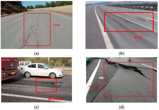
Figure 1. (a) The diagram of crack; (b) The diagram of rut; (c) The diagram of groove; (d) The diagram of subsidence.
Cracks are one of the most common diseases on the pavement. It mainly has transverse cracks, longitudinal cracks, and reticular cracks. It is extremely harmful to the road surface. Especially in winter and spring, due to the infiltration of rain and snow water, the road disease that is already in a crack state is more serious under the action of driving load [2]. Ruts are the permanent grooves in the road surface under the repeated action of vehicle loads [3]. This is mainly due to the unreasonable design of the asphalt mixture gradation or insufficient compaction during construction. This can make the road surface drainage poorly on rainy days, and the driving vehicle is prone to drifting and affecting the safety of high-speed driving. The grooves [4] are mainly formed due to the lack of timely maintenance after the surface layer is cracked, which has the potential to cause a flat tire in a moving vehicle and cause a traffic accident. These defects can bring damage to the vehicles on the road. Uneven or irregular roads can lead to tire wear. What is more, it can lead to a flat tire and cause a traffic accident. To ensure driving safety, the funding for road maintenance is increasing every year [5]. Identifying road defects timely is important for pavement maintenance. Manual inspection is intuitive with the high cost and low efficiency. In order to solve this problem, various intelligent detection methods for road surface defects detection have been developed [6]. However, there is a lack of studies summarizing the advantage and disadvantages of those intelligent detection methods.
2. Camera
Many researchers used cameras for pavement image collection [11,12,13,14,15]. The image can then be used for pavement texture analysis [16], pavement crack detection [17], and asphalt mixture crack detection [18]. Y. Du et al. [19] collected a large number of pavement defect images, including timestamp and location information, using car-mounted cameras. Repeated collection and overlapping of pavement defects images were found during the collection process. Therefore, a feature matching and image mosaic method for pavement disease detection based on multi-vehicle images was proposed. Tang [20] developed intelligent road inspection equipment with existing road inspection vehicles installed with cameras. The qualitative and quantitative assessment of road surface quality can be then achieved. Du et al. [21] used the high-resolution industrial cameras installed on vehicles to collect pavement images. The detection and classification method of pavement diseases based on the You Only Look Once (YOLO) network was combined. Grabowski, D. et al. [22] proposed a method for estimating pavement conditions based on images obtained from onboard cameras. A set of algorithms was created to process images from depth cameras and RGB (red, green, blue) cameras. The neural network model was trained by video samples from the camera for road defects classification. Studies showed that the processing accuracy of the application of digital image processing technology reached more than 80%. Jahanshahi, M. R. et al. [23] used RGB-D sensors to detect and quantify pavement defects. The sensor system consisted of an RGB color image, an infrared projector, and a camera as a depth sensor. Combined with the corresponding algorithm, the automatic detection of road diseases such as cracks and potholes can be completed. In addition, the global positioning system was combined with the proposed system to locate the detected defects. It can be used as an auxiliary sensor system for road surface assessment vehicles. Cui, X et al. [24] used profiling and digital image technology to achieve a three-dimensional reconstruction of asphalt pavement contours. Image processing technology helped to locate the precise coordinates of each point on the model. According to the contour method, a comprehensive calculation program for texture depth was established.
With the development of unmanned aerial vehicles (UAVs), more and more pavement engineers or researchers are starting to install cameras on UAVs for the detection of various road diseases [25,26,27], as shown in Figure 3. Junqing, Z. et al. [28] proposed that the road detects information were collected by drones using high-resolution cameras. A drone platform for road surface image acquisition was assembled, and the flight settings were studied to obtain optimal image quality. The acquired images were processed and annotated for model training. Combined with the YOLOv3 algorithm, the average accuracy (MAP) of data processing was 56.6%. Zhijian, M. et al. [29] analyzed the development technology of unmanned aerial vehicles in the field of intelligent transportation to improve the accuracy of road surface disease detection. A framework for road disease recognition and perception based on drones was constructed. The Yuneec H520 UAV was used to collect road surface image data, and the road surface disease image preprocessing technology based on wavelet threshold transformation was analyzed. Inzerillo, L. et al. [30] used data collected by drones to analyze structural self-motion (SfM) techniques at different heights. This technology was applied to old pavements on the campus of the University of Palermo. The technology accurately identified pavement diseases and developed an integrated approach to optimizing pavement management strategies.
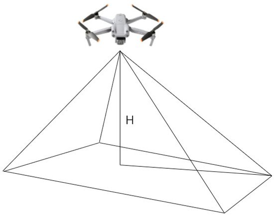
Figure 3. Aerial model of a drone.
Cameras are widely used in pavement disease detection technology. It has a high dynamic range and resolution, and it is inexpensive. However, the imaging of the camera is greatly affected by the lighting conditions of the road surface under test. The light intensity is too strong, too weak, or the light is uneven and is not conducive to imaging. In order to ensure that the system can work properly in any environment, auxiliary lighting equipment needs to be configured to provide uniform lighting conditions and ensure image quality. Moreover, the camera provides only 2D information and lacks depth information, which is not conducive to a more comprehensive analysis of the problem [29,31,32].
3. GPR
Compared to the camera, GPR detection technology [33,34] is more efficient for identifying roadbed diseases. This method does not need to destroy or excavate road surfaces and can effectively overcome the concealment of roadbed diseases.
Road disease detection is an important basis for road maintenance and maintenance. Although the conventional drill core sampling method can achieve the purpose of pavement inspection, the detection results of this method are not comprehensive, and the damage to the pavement is large. As an efficient non-destructive testing technology, ground-penetrating radar offers the possibility of non-destructive testing of road diseases. Zhu et al. [35] discussed the effects of diseases such as road surface reflection cracks, subsidence, and uneven pavement on ground-penetrating radar image results, as shown in Figure 4 and Figure 5. Based on the influence of diseases on the image results of ground-penetrating radar and the detection results of ground-penetrating radar, the types and causes of road lesions in a certain section of the highway were successfully analyzed. Gao, J. et al. [36] used ground-penetrating radar (GPR) for road surface damage detection. Data processing in conjunction with the faster R-ConvNet algorithm to complete the task. The results showed that the accuracy was 89.13%. The stability of this model was better under different road structures. One of the problems encountered when conducting non-destructive testing of the road surface with ground-penetrating radar is the detection of multi-layered reflectors in the echoes of ground-penetrating radar. Lahouar, S. et al. [37] solved this problem by iteratively detecting strong reflections in GPR signals by using threshold or match filter detectors. The detected pulses were then used in the reflection model to synthesize a signal that is “similar” to the measured ground-penetrating radar signal in the least-squares sense. The synthesized signal was then subtracted from the measured signal to show the faint reflections that were masked. Then these reflections were detected iteratively using the same method. After testing, the study can be successful in disease detection. To test and evaluate the field application effect of asphalt pavement ground-penetrating radar rapid detection technology, Zhang et al. [38] conducted on-site test research based on the key points and implementation process of on-site detection technology. They relied on physical engineering and analyzed the accuracy of the detection results. The results showed that the compaction of the asphalt surface layer detected by ground-penetrating radar on-site was relatively accurate. The relative error can be controlled by 1%. The on-site detection results of the pavement disease ground penetrating radar were consistent with the scoring results, and the scanning image of the ground-penetrating radar can clearly reflect the structural condition of the asphalt pavement. To study the defect detection and identification of the road surface by ground-penetrating radar (GPR), Huang et al. [39] proposed a method with obvious effects on improving abnormal resolution and singular value decomposition by embedding metal plates at the interface of each layer in the surface of the road surface. It was applied to road field detection. The results showed that this can reduce the amount of work processing data and increase the accuracy of the detection.
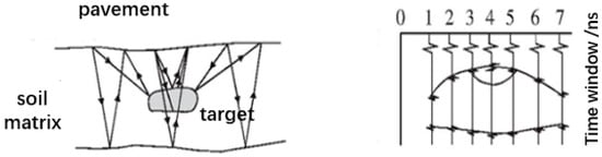
Figure 4. GPR detection process.
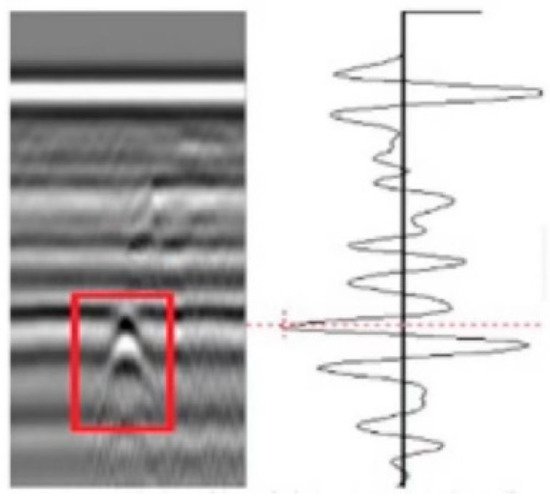
Figure 5. Image of flaw reflection echo on GPR.
Ground-penetrating radar is a non-destructive and fast method of pavement detection. It mainly has the following characteristics [40]. Its adaptability is strong. Geological radar can be safely applied to the city or construction site of the engineering site by the use of non-destructive testing technology. The working conditions are more relaxed. Its anti-interference ability is strong, and its anti-electromagnetic interference ability is strong [41]. It can work in various noise environments in the city and is less affected by the bad environment. Its positioning is fast and accurate. It has better inspection depth and resolution and can provide real-time cross-sectional views directly with clear and intuitive images [42]. It uses a laptop to control the acquisition, recording, storage, and processing of data for ease of portability. However, the big data obtained by the ground-penetrating radar delay the processing time, which leads to problems such as subjectivity in data interpretation [43,44].
4. LiDAR
LiDAR is an emerging device for road surface defects detection with the unique advantages of high precision, high resolution, high automation, and high efficiency [45,46], as shown in Figure 6.
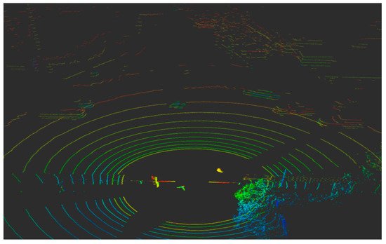
Figure 6. Point cloud data collected by LiDAR.
Zhang et al. [47] conducted data comparison and analysis on the stability of the specified laser road condition detection equipment from three angles (flatness, surface section construction depth, and rut) in ordinary roads and special test roads. The applicability of laser detection was demonstrated. Suggestions and methods for improving the reliability of equipment detection were proposed. Zhao [48] proposed a change detection method based on a digital elevation model and density map by using point cloud data obtained by vehicle-mounted LiDAR scanning. After verification, the detection accuracy of this method can reach 93.1%. M.Bellone et al. [49] detected the uneven position on the road by studying the driver warning system. LiDAR was used to generate the environment in the form of a three-dimensional (3D) point cloud, which was analyzed and processed based on a normal vector and presented to the driver in the form of a traversable grid. Li et al. [50] adopted line laser technology to construct a 3D data acquisition system for pavement and collected high-resolution (0.5 mm) 3D pavement depth data. Yan et al. [51] used LiDAR to detect road irregularity information. Road environmental information was extracted and segmented by the network structure of random sampling and local feature aggregation. In order to solve the problem of the loss of key features in the process of road environment information segmentation, a local feature aggregator was added to increase the acceptance domain of each 3D point cloud to retain geometric details. The results showed that the method could accurately identify the road environment information, and the recognition accuracy of the convex hull, pit, and drivable area can reach 71.87%, 82.71%, and 93.01%, respectively. Jiang et al. [52] took advantage of the three-dimensional data of the pavement to propose an enhanced dynamic optimization algorithm to improve crack segmentation. The four most common types of pavement cracks (longitudinal, transverse, block, and crocodile-like) were tested. Experimental results showed that the average calculation time of the algorithm was greatly shortened. At the same time, cracks in multiple directions were better handled, and the accuracy of crack segmentation was improved. Song [53] took the three-dimensional line laser technology as the research object and analyzed its system composition and working principle. Comprehensively engineering examples were introduced to discuss its application effect in road rutting detection and the factors affecting the detection results so as to provide a reference for road rutting detection. Guo et al. [54] applied the new three-dimensional laser detection technology with high precision and high density, and the indoor rutted pattern simulation equipment was developed to quantitatively evaluate the detection accuracy and reliability of the non-uniform 13-point laser rutting detection equipment for the problem of rut depth. The results showed that the detection error and dispersion of the 13-point laser detection equipment for the bump type rut were significantly higher than those for the detection of no bump rut, and the relative error exceeded 5%. Hu et al. [55] used a non-uniform 13-point laser detection device to obtain cross-sectional data from 110 sets of measured rutted vehicles. The effect of lateral offset of multi-point laser detection vehicles on the error of depth detection of rutted vehicles in different forms was studied. To evaluate the pavement quality completely and intuitively, Wang et al. [56] proposed a three-dimensional pavement detection method based on a laser displacement sensor and gyroscope. The results showed that the method can measure the pavement shape of the entire lane with high detection accuracy and fast detection speed.
The detection distance of LiDAR is long, and the angle measurement accuracy is high. What is more, the resolution is high, and the viewing angle is wide. However, it is susceptible to natural light and thermal radiation, and it is greatly disturbed in weather such as rain and fog, wind and sand, etc. The working environment requirements are high, and the cost is high [57,58,59].
5. IMU
The IMU installed on the detection vehicle can detect whether the road surface is damaged by analyzing the data of the acceleration sensor, angular velocity sensor, and other components [60,61,62], as shown in Figure 7. Acceleration changes, angular velocity changes, and attitude changes in the process of vehicle movement can all be collected by IMU, which requires a small amount of calculation and can achieve high accuracy [63,64,65].
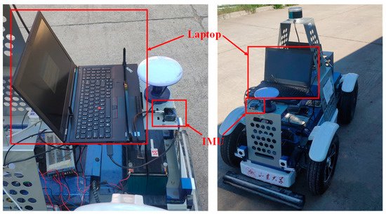
Figure 7. IMU fixed to the inspection vehicle.
M. et al. [66] presented a road surface defect identification system based on 3D accelerometers, a global positioning system (GPS), and video modules deployed on vehicles. Anthony et al. [67] applied IMU and laser to evaluate road roughness and generate road profile, improving the accuracy of vehicle-based longitudinal road profilometer in road roughness and large texture evaluation. Christodoulou et al. [68] inputted acceleration and angular velocity data into the designed artificial neural network to distinguish potholes on the road, and the detection accuracy was about 90%. In order to solve the drift problem of velocity and avoid affecting the accuracy of calculation and target positioning, a method for velocity and displacement calculation based on stable numerical integration was proposed by Kong et al. [69] The results showed that this method can reduce the drift error and improve the accuracy of the integral results.
IMU is an autonomous system that does not rely on any external information and does not radiate energy to the outside. It is well concealed and is not affected by external electromagnetic interference. Plus, it can work at all times. It has a high data update rate, short-term accuracy, and stability. However, because the navigation information is generated by integration, the positioning error increases with time, it requires a long initial alignment time before each use, and the price of the device is expensive [70,71,72,73].
This entry is adapted from the peer-reviewed paper 10.3390/su14106306
This entry is offline, you can click here to edit this entry!