Floating offshore wind turbines (FOWT) have attracted more and more attention. Environmental loads on FOWTs have higher complexity than those on the traditional onshore or fixed-bottom offshore wind turbines. In addition to aerodynamic loads on turbine blades, hydrodynamic loads also act on the support platform. The primary coupling method is based on the combination of BEM theory and potential flow theory, which can simulate the performance of the FOWT system under normal operating conditions but has certain limitations in solving the complex problem of coupled FOWTs. The more accurate and reliable CFD method used in the research of coupling problems is still in its infancy.
1. Introduction
Over the last few decades, global climate change and energy supply have become ever more significant for society. The interest in the exploitation of renewable energies is increasing significantly worldwide. As a clear alternative to fossil fuels, wind power shows excellent potential in the energy structure of the future decarbonized world.
The development and utilization of wind energy has a long history. From the use of sails for marine navigation in about 3000 BC to the modern use of large-scale offshore wind turbines for wind power generation, wind energy development technology has become increasingly sophisticated. The onshore wind power industry has developed rapidly since 2000 and has gradually matured with the support of governments and the development of technology. As a result, onshore wind resources that can be used have become scarcer, and high-quality wind farms have become fewer and fewer. Compared with onshore, offshore wind energy reserves are larger, have broader distribution, and wind speed is more stable. Therefore, wind turbines have gradually moved from land to ocean and from shallow to deep sea.
With offshore wind turbines moving further from the shore, the economic cost of the traditional bottom-fixed type increases significantly. The concept of floating offshore wind turbines (FOWTs) was proposed in 1972
[1]. FOWT costs are anticipated to follow a similar downward trajectory as onshore sectors and are expected to decrease by 37–49% by 2050
[2]. With the development of technology and the significant increase in turbine sizes, FOWTs may gradually become the main force in the development and utilization of wind energy offshore in the future (
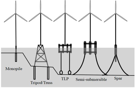
Figure 1).
Figure 1. Types of offshore wind turbines.
Since the concept of floating wind turbine was first proposed, many different forms of the platform concepts have been developed.
In 2004, Withee
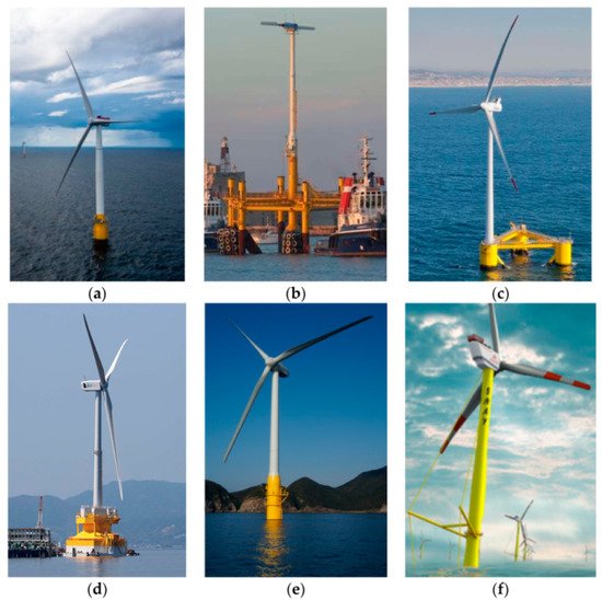
[3] proposed a combined foundation of a tension-leg platform (TLP), spar and barge platform and adopted the radial mooring of a spar platform. In 2009, Equinor ASA built the world’s first officially operational FOWT named Hywind (
Figure 2a). Based on the single-pillar floating platform, Hywind works at a depth of 200 m with three anchor chains. Blue H installs a TLP FOWT (
Figure 2b). In 2009, the National Renewable Energy Laboratory (NREL)
[4] integrated WindPACT, RECOFF and DOWEC projects to develop a 5 MW benchmark wind turbine. In 2010, Jonkman
[5][6] modified the parameters of Hywind and designed a semi-submersible platform foundation in the OC4 project based on the 5 MW OC3-Hywind FOWT project. In 2011, Principle Power installed a 2 MW three-pillar semi-submersible FOWT called WindFloat with an operating water depth of 45 m and four catenaries for mooring (
Figure 2c). In 2013, Japan installed two FOWTs, including a semi-submersible FOWT named Fukushima (
Figure 2d) and a single-pillar FOWT named GOTO (
Figure 2e). In addition to typical models mentioned above, the company Danish Sway also proposed a Spar/TLP hybrid structure (
Figure 2f).
Figure 2. Typical Floating Offshore Wind Turbines. (
a) Hywind
[7]; (
b) Blue H
[8]; (
c) WindFloat
[7]; (
d) Fukushima
[9]; (
e) GOTO
[10]; (
f) Sway
[11].
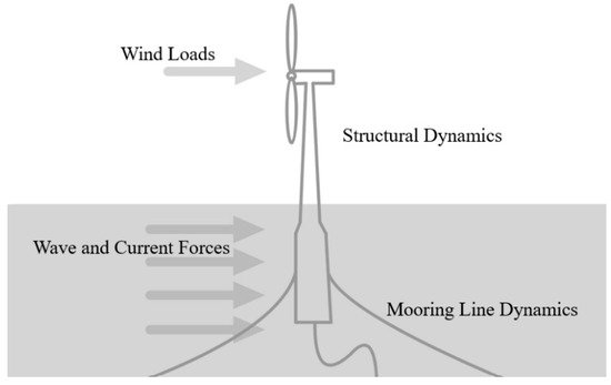
The FOWT system generally includes four parts: wind turbine (including blades, hubs, nacelles, etc.), tower, floating support platform, and mooring system. Movements of one part can affect other parts of the structure. Because of the FOWT system structure and the complicated offshore environment, environmental loads on FOWTs are more complicated than those on onshore wind turbines (Figure 3). In addition to aerodynamic loads on turbine blades, there are also hydrodynamic loads acting on the support platform and mooring loads acting on the mooring system. In addition, FOWTs working in special environments may bear more complicated environmental loads. For example, when FOWTs operate in ice areas, the impact of ice on the structure and hydrodynamic performance must be considered. It is worth noting that environmental loads acting on FOWTs are not independent but coupled with each other. Therefore, in the field of FOWT research, the focus has always been on analyzing the coupled dynamic performance accurately under the premise of complex environmental loads.
Figure 3. Sketch of environmental loads on a floating offshore wind turbine.
2. Coupled Dynamic Analysis
Compared with onshore wind turbines, floating wind turbines work in a more complex marine environment: the upper wind turbine bears wind loads, and the floating support platform and mooring system are subject to the combined action of waves and ocean currents. Moreover, mutual coupling will occur between the various parts of the structure. On one hand, the aerodynamic load received by the upper wind turbine will be transmitted to the platform through the tower. The movement of the platform under this action is no longer a simple response under waves especially as the size of the wind turbine continues to increase. On the other hand, the motion response of the platform under the combined action of the wave and mooring system will be transmitted to the upper wind turbine through the tower, which will change the aerodynamic loads and output power of the wind turbine.
The numerical simulation of the aerodynamic performance of wind turbine and the hydrodynamic performance of floating platform provides a certain reference for the design and research of FOWT system. In order to simulate the performance of FOWT system more accurately under normal operating conditions, it is necessary to simulate the aerodynamic-hydrodynamic fully coupled numerical simulation of FOWTs.
With the further development of the research on aerodynamic and hydrodynamic performance analysis of FOWT and the advancement of computing technology, the full coupling analysis of the aerodynamic and hydrodynamic loads of FOWT is now possible. More and more scholars are focusing on coupled analysis of FOWT system.
At present, some software for coupled analysis of FOWTs is based on the existing onshore wind turbine simulation program, adding the simulation of floating platform and mooring system. Others add a wind turbine aerodynamic simulation module on the basis of original floating platform hydrodynamic simulation code. In order to analyze and compare the accuracy of different numerical calculation procedures, the International Energy Agency organized “wind energy task 30”
[12] and used 24 different numerical calculation procedures to analyze the dynamic response of 5 MW semi-submersible FOWT in OC4 project, which has played a guiding role in the development of numerical calculation program of FOWT.
Table 1 [12] shows several typical theoretical modeling codes and methods.
Table 1. List of codes for fully coupled aero-hydrodynamic analysis of floating offshore wind turbines.
| Code |
Code Developer |
Aerodynamics |
Hydrodynamics |
Mooring Model |
| FAST v8 |
NREL |
(BEM or GDW) + DS |
PF + ME |
QS |
| SIMPACK + HydroDyn |
SIMPACK |
BEM or GDW |
PF + QD |
QS |
| Bladed (Advanced Hydro beta) |
DNV GL |
(BEM or GDW) + DS |
PF + ME + (IWL) |
QS |
| Sino, Riflex + Aerodyn |
MARINTEK, NREL |
(BEM or GDW) + DS |
PF + ME |
FE/Dyn |
| HAWC2 |
DTU Wind |
(BEM or GDW) + DS |
ME |
FE/Dyn |
National Renewable Energy Laboratory (NREL) has carried out a lot of research work on FOWTs and made great contributions to the research. In 2006, Jonkman and Sclavounos
[13] of MIT improved the calculation software FAST developed by NREL, enhancing its preprocessor Adams function and integrating it with swim-motion-lines software and WAMIT software developed by MIT to make it suitable for the numerical calculation of dynamic response of FOWTs. In 2007, Jonkman
[14] introduced HydroDyn module and mooring module into FAST, making it a numerical full coupling analysis program of aerodynamic analysis, hydrodynamic analysis, servo control and elastic analysis.
Norwegian University of Science and Technology has also done a lot of works on the development of numerical calculation program for FOWT. Linde
[15] used Simo to analyze the dynamic response of 5 MW FOWT in OC3 project. Thomas
[16] integrated HydroD, DeepC and TDHMILL3D to conduct fully coupled numerical calculation for TLP, Spar and semi-submersible FOWTs.
The fully coupled numerical simulation of FOWTs is still in its infancy. Most studies are based on the above-mentioned methods of aerodynamic and hydrodynamic simulation. However, some traditional aerodynamic or hydrodynamic analysis methods have been found unreasonable to be directly used in coupled analysis. Roddier
[17] pointed out that the empirical characteristics of Morison’s equation and potential flow theory do not help the design of a new supporting platform. Sebastian and Lackner
[18] pointed out that traditional BEM plus some corrections (such as dynamic inflow, yaw model, etc.) cannot accurately describe the interaction between blades and wake. Moreover, the commonly used stall models such as the semi-empirical B-L model and their applicability to FOWTs have not been fully studied. Therefore, it is necessary to develop more advanced FOWT modeling methods and coupled analysis models.
Due to the complexity of the aerodynamic-hydrodynamic coupled analysis, the full-model and real-scale CFD numerical simulation will become the most ideal tool. For large-scale FOWTs, there are not only complicated structures but also multi-scale effects, which brings great challenges to the study of the fully coupled analysis of FOWTs using CFD methods. Nematbakhsh
[19] used the CFD method to conduct a preliminary study on the coupled effect of FOWT. They simplified loads on blades to constant thrust and used the single-phase flow Navier–Stokes equation to study the dynamic response of a TLP FOWT system. Quallen
[20] conducted a two-phase flow CFD simulation of FOWT system. They used overset technology to deal with the grid movement around the platform and blades.
In general, the research based on CFD methods is still in its infancy. There are still many unresolved difficulties in CFD methods, such as the division of the calculation domain of the water and gas flow field, the selection of the time step, the time calculation of the random wave action and so on.
This entry is adapted from the peer-reviewed paper 10.3390/en15113970


