You're using an outdated browser. Please upgrade to a modern browser for the best experience.
Please note this is an old version of this entry, which may differ significantly from the current revision.
Subjects:
Engineering, Electrical & Electronic
近年来,浮动式海上风力涡轮机(FOWT)越来越受到关注。然而,与传统的陆上或固定底部海上风力涡轮机相比,FOWT上的环境负荷具有更高的复杂性。除了涡轮叶片上的空气动力载荷外,流体动力载荷还作用于支撑平台。
目前,初级耦合方法是基于BEM理论和势流理论的结合,可以模拟FOWT系统在正常工作条件下的性能,但在求解耦合FOWT的复杂问题方面存在一定的局限性。用于耦合问题研究的更准确可靠的CFD方法仍处于起步阶段。未来,应充分运用多学科理论,从全局角度研究流体力学和空气动力学的耦合动力学,这对于FOWT的设计和大规模利用具有重要意义。
- floating offshore wind turbine
- aerodynamic loads
- hydrodynamic loads
1. 引言
在过去的几十年里,全球气候变化和能源供应对社会的影响越来越大。全世界对可再生能源开发的兴趣正在显著增加。作为化石燃料的明显替代品,风力发电在未来脱碳世界的能源结构中显示出巨大的潜力。
风能的开发利用历史悠久。从公元前3000年左右使用帆进行海上航行到现代使用大型海上风力涡轮机进行风力发电,风能开发技术变得越来越复杂。陆上风电产业自2000年以来发展迅速,并在政府支持和技术发展的推动下逐渐成熟。因此,可以使用的陆上风力资源变得越来越稀缺,高质量的风电场变得越来越少。与陆上相比,海上风能储量更大,分布更广,风速更稳定。因此,风力涡轮机逐渐从陆地转移到海洋,从浅海到深海。
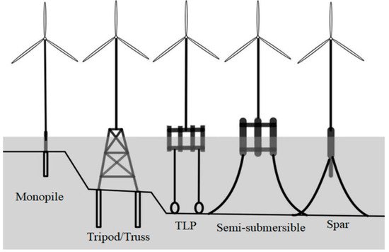
随着海上风力发电机组离岸方的距离越来越远,传统底部固定式风电的经济成本显著增加。浮动海上风力涡轮机(FOWTs)的概念于1972年提出[1]。预计FOWT成本将遵循与陆上行业类似的下降轨迹,预计到2050年将下降37-49%[2]。随着技术的发展和涡轮机尺寸的显著增加,未来FOWT可能逐渐成为海上风能开发利用的主力军(图1)。

图 1.海上风力涡轮机的类型。
自首次提出浮动风力发电机的概念以来,已经开发了许多不同形式的平台概念。
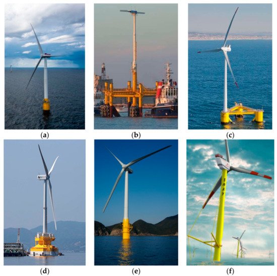
2004年,Withee [3]提出了张力腿平台(TLP),翼梁和驳船平台的组合基础,并采用了翼梁平台的径向系泊。2009年,Equinor ASA建造了世界上第一个名为Hywind的正式运营的FOWT(图2a)。基于单柱浮动平台,Hywind在200米深处使用三个锚链工作。蓝色 H 安装 TLP FOWT(图 2b)。2009年,国家可再生能源实验室(NREL)[4]整合了WindPACT,RECOFF和DOWEC项目,以开发5兆瓦的基准风力涡轮机。2010年,Jonkman [5,6]修改了Hywind的参数,并在OC4项目中设计了基于5兆瓦OC3-Hywind FOWT项目的半潜式平台基础。2011年,Principle Power安装了一台2兆瓦的三柱半潜式FOWT,名为WindFloat,工作水深为45米,并安装了四个用于系泊的悬链线(图2c)。2013年,日本安装了两台FOWT,包括一个名为福岛的半潜式FOWT(图2d)和一个名为GOTO的单柱FOWT(图2e)。除了上面提到的典型模型外,丹麦Sway公司还提出了一种Spar/TLP混合结构(图2f)。
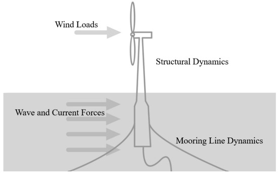
FOWT系统一般包括四个部分:风力发电机组(包括叶片、轮毂、机舱等)、塔架、浮动支撑平台和系泊系统。一个部件的运动会影响结构的其他部分。由于FOWT系统结构和复杂的海上环境,FOWT上的环境负荷比陆上风力涡轮机上的环境负荷更复杂(图3)。除了涡轮叶片上的空气动力载荷外,还有作用于支撑平台的流体动力载荷和作用于系泊系统的系泊载荷。此外,在特殊环境中工作的FOFT可能承受更复杂的环境负荷。例如,当FOFT在冰区运行时,必须考虑冰对结构和流体动力学性能的影响。值得注意的是,作用于FOFT上的环境负荷不是独立的,而是相互耦合的。因此,在FOWT研究领域,重点始终是在复杂环境负荷的前提下,准确分析耦合动态性能。

Figure 3. Sketch of environmental loads on a floating offshore wind turbine.
2. Coupled Dynamic Analysis
Compared with onshore wind turbines, floating wind turbines work in a more complex marine environment: the upper wind turbine bears wind loads, and the floating support platform and mooring system are subject to the combined action of waves and ocean currents. Moreover, mutual coupling will occur between the various parts of the structure. On one hand, the aerodynamic load received by the upper wind turbine will be transmitted to the platform through the tower. The movement of the platform under this action is no longer a simple response under waves especially as the size of the wind turbine continues to increase. On the other hand, the motion response of the platform under the combined action of the wave and mooring system will be transmitted to the upper wind turbine through the tower, which will change the aerodynamic loads and output power of the wind turbine.
The numerical simulation of the aerodynamic performance of wind turbine and the hydrodynamic performance of floating platform provides a certain reference for the design and research of FOWT system. In order to simulate the performance of FOWT system more accurately under normal operating conditions, it is necessary to simulate the aerodynamic-hydrodynamic fully coupled numerical simulation of FOWTs.
With the further development of the research on aerodynamic and hydrodynamic performance analysis of FOWT and the advancement of computing technology, the full coupling analysis of the aerodynamic and hydrodynamic loads of FOWT is now possible. More and more scholars are focusing on coupled analysis of FOWT system.
At present, some software for coupled analysis of FOWTs is based on the existing onshore wind turbine simulation program, adding the simulation of floating platform and mooring system. Others add a wind turbine aerodynamic simulation module on the basis of original floating platform hydrodynamic simulation code. In order to analyze and compare the accuracy of different numerical calculation procedures, the International Energy Agency organized “wind energy task 30” [40] and used 24 different numerical calculation procedures to analyze the dynamic response of 5 MW semi-submersible FOWT in OC4 project, which has played a guiding role in the development of numerical calculation program of FOWT. Table 1 [40] shows several typical theoretical modeling codes and methods.
Table 1. List of codes for fully coupled aero-hydrodynamic analysis of floating offshore wind turbines.
| Code | Code Developer | Aerodynamics | Hydrodynamics | Mooring Model |
|---|---|---|---|---|
| FAST v8 | NREL | (BEM or GDW) + DS | PF + ME | QS |
| SIMPACK + HydroDyn | SIMPACK | BEM or GDW | PF + QD | QS |
| Bladed (Advanced Hydro beta) | DNV GL | (BEM or GDW) + DS | PF + ME + (IWL) | QS |
| Sino, Riflex + Aerodyn | MARINTEK, NREL | (BEM or GDW) + DS | PF + ME | FE/Dyn |
| HAWC2 | DTU Wind | (BEM or GDW) + DS | ME | FE/Dyn |
GDW: generalized dynamic wake; DS: dynamic stall; PF: potential flow; ME: Morison’s equation; QD: quadratic drag; IWL: instantaneous water level; QS: quasi-static; Dyn: dynamic; FE: finite element.
National Renewable Energy Laboratory (NREL) has carried out a lot of research work on FOWTs and made great contributions to the research. In 2006, Jonkman and Sclavounos [41] of MIT improved the calculation software FAST developed by NREL, enhancing its preprocessor Adams function and integrating it with swim-motion-lines software and WAMIT software developed by MIT to make it suitable for the numerical calculation of dynamic response of FOWTs. In 2007, Jonkman [42] introduced HydroDyn module and mooring module into FAST, making it a numerical full coupling analysis program of aerodynamic analysis, hydrodynamic analysis, servo control and elastic analysis.
Norwegian University of Science and Technology has also done a lot of works on the development of numerical calculation program for FOWT. Linde [43] used Simo to analyze the dynamic response of 5 MW FOWT in OC3 project. Thomas [44] integrated HydroD, DeepC and TDHMILL3D to conduct fully coupled numerical calculation for TLP, Spar and semi-submersible FOWTs.
The fully coupled numerical simulation of FOWTs is still in its infancy. Most studies are based on the above-mentioned methods of aerodynamic and hydrodynamic simulation. However, some traditional aerodynamic or hydrodynamic analysis methods have been found unreasonable to be directly used in coupled analysis. Roddier [45] pointed out that the empirical characteristics of Morison’s equation and potential flow theory do not help the design of a new supporting platform. Sebastian and Lackner [46] pointed out that traditional BEM plus some corrections (such as dynamic inflow, yaw model, etc.) cannot accurately describe the interaction between blades and wake. Moreover, the commonly used stall models such as the semi-empirical B-L model and their applicability to FOWTs have not been fully studied. Therefore, it is necessary to develop more advanced FOWT modeling methods and coupled analysis models.
Due to the complexity of the aerodynamic-hydrodynamic coupled analysis, the full-model and real-scale CFD numerical simulation will become the most ideal tool. For large-scale FOWTs, there are not only complicated structures but also multi-scale effects, which brings great challenges to the study of the fully coupled analysis of FOWTs using CFD methods. Nematbakhsh [47] used the CFD method to conduct a preliminary study on the coupled effect of FOWT. They simplified loads on blades to constant thrust and used the single-phase flow Navier–Stokes equation to study the dynamic response of a TLP FOWT system. Quallen [48] conducted a two-phase flow CFD simulation of FOWT system. They used overset technology to deal with the grid movement around the platform and blades.
In general, the current research based on CFD methods is still in its infancy. There are still many unresolved difficulties in CFD methods, such as the division of the calculation domain of the water and gas flow field, the selection of the time step, the time calculation of the random wave action and so on.
This entry is adapted from the peer-reviewed paper 10.3390/en15113970
This entry is offline, you can click here to edit this entry!

