Your browser does not fully support modern features. Please upgrade for a smoother experience.
Please note this is an old version of this entry, which may differ significantly from the current revision.
Subjects:
Metallurgy & Metallurgical Engineering
Material extrusion additive manufacturing of metal (metal MEX), which is one of the 3D printing processes, has gained more interests because of its simplicity and economics. Metal MEX process is similar to the conventional metal injection moulding (MIM) process, consisting of feedstock preparation of metal powder and polymer binders, layer-by-layer 3D printing (metal MEX) or injection (MIM) to create green parts, debinding to remove the binders and sintering to create the consolidated metallic parts.
- material extrusion
- 3D printing
- fused filament fabrication
- metal injection moulding
1. Introduction
From the ISO/ASTM 52900, additive manufacturing (AM), usually known as 3D-printing, is a process of joining materials to make parts from 3D model data, usually layer by layer, as opposed to subtractive manufacturing and formative manufacturing methodologies [1]. This process has become increasingly popular for various material fabrications, such as ceramic, polymer and metal [2,3,4,5]. Many metal AM processes, such as powder bed fusion (PBF), direct energy deposition (DED) and materials extrusion (MEX) can successfully fabricate various metals, e.g., stainless steel [6,7,8,9], titanium alloys [10,11,12,13], nickel alloys [14,15,16,17,18], cobalt [19,20] and aluminium alloys [21,22,23,24,25]. AM can also provide a high degree of freedom, lightweight design with almost unlimited shape, complexity and a varied range of sizes depending on the printing process [26]. In addition, the AM parts are not only limited to prototyping, but can be applied in various technologies, including modelling, pattern-making, tool-making and end-use parts productions with very high growth rates [27]. Hence, AM parts can be served in many industries, e.g., biomedical, aerospace and energy applications [3,28]. Among the several techniques of metal AM, metal MEX utilises low-cost equipment with simplicity and safety, as neither loose metal powder nor a high-power source is required when compared to other common metal AM processes, i.e., laser powder bed fusion (LPBF) and electron beam powder bed fusion (EPBF) [9,29]. During the last decade, this metal MEX process has attracted more attention due to the as-mentioned advantages and the familiarities with conventional polymer 3D printing, which is the metal-fused filament fabrication process (FFF), usually called fused deposition modelling (FDM). Figure 1 shows the number of publications relating to metal MEX per year and the cumulative number.
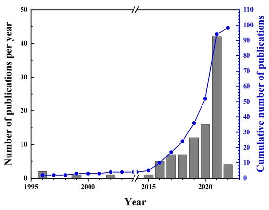
Figure 1. Number of publications relating to the metal MEX from 1996 to February 2022. Data from [4,5,8,9,29,30,31,32,33,34,35,36,37,38,39,40,41,42,43,44,45,46,47,48,49,50,51,52,53,54,55,56,57,58,59,60,61,62,63,64,65,66,67,68,69,70,71,72,73,74,75,76,77,78,79,80,81,82,83,84,85,86,87,88,89,90,91,92,93,94,95,96,97,98,99,100,101,102,103,104,105,106,107,108,109,110,111,112,113,114,115,116,117,118,119,120,121,122,123].
The nature of metal MEX is very similar to the conventional metal injection moulding (MIM) [124,125]. The overall MIM and metal MEX processing steps are presented in Figure 2a,b,d,e and Figure 2a,c,d,e, respectively. The MIM process starts with the mixing of sinterable metal powder with suitable polymeric binders and then granulating the metal-binder mixture into feedstock Figure 2a. The feedstock is subsequently injected into a mould to create the injected part, commonly called a “green part” (Figure 2b). The polymeric binders are then removed by solvent (optional) and thermal debinding (Figure 2d) before the debound parts are sintered in a controlled atmosphere, e.g., H2, N2, Ar or vacuum atmosphere, to densify the parts (Figure 2e). During sintering, necks are formed to bond between adjacent powder particles, consolidation takes place and voids are closed. This causes shrinkage of the sintered part, which in theory should be uniform. However, in practice, the uniformity of shrinkage depends on several factors, e.g., the homogeneity of feedstock and the resultant green parts, geometry, gravity and friction between the parts and sintering tray. Typical MIM shrinkage lies within the range of 12–20% [125,126,127]. Hence, the mould cavity needs to be oversized to compensate for the shrinkage. After sintering, the density of the MIMed specimen can reach up to 99% of the theoretical density. Hot isostatic pressing (HIP) can be applied, if high mechanical property and density are required. For the metal MEX, instead of forming the green part by the injection moulding process, it is printed layer by layer (the process in Figure 2b is replaced by that in Figure 2c) with various forms of feedstock, i.e., granule, bar and filament, depending on the printer. After printing, the subsequent debinding and sintering steps (Figure 2d,e) may be slightly different from the MIM process due to the differences in compositions of binders and the metal powder fraction (usually named “solid loading”), metal powder size and its distribution. The shrinkage of the sintered metal MEX part is generally higher than for MIM parts because the metal MEX feedstock usually has higher binder content (lower solid loading) than MIM so that the metal MEX feedstock is printable and can be easily handled. Therefore, dimensions of the CAD model need to be carefully compensated to acquire the required dimension after sintering. The sintered density and mechanical properties of the metal MEX part are theoretically lower than those of MIM due to the voids between deposited paths generated during printing [8]. Thereby, the print strategy, which can generate not only such voids but also deflection and incomplete weld in polymer 3D-print parts [128,129,130], needs to be carefully controlled for metal MEX before progressing to the debinding and sintering.
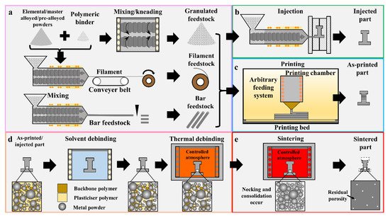
Figure 2. Comparison of material extrusion additive manufacturing of metal (a,c,d,e) and metal injection moulding (a,b,d,e).
2. Material Extrusion Additive Manufacturing of Metal (Metal MEX)
In metal MEX, the feedstock composing of metal powder and polymeric binders is heated until the filament is softened and can be extruded through a printing nozzle. The printed material is then deposited on the printing bed, which is heated to increase adhesion between the printed parts and the printing bed so that the 3D part is created layer-by-layer following the CAD model [131]. This metal MEX process can also fabricate multi-material 3D parts, when a printer has more than one printing head or feeding system. Depending on the feeding system of the printer, the metal MEX process can be classified into three types, as presented in Figure 3, which are (a) screw-based, (b) plunger-based and (c) filament-based types [132]. After printing, the as-printed parts require to be debound and sintered in a similar manner to those in the MIM processing steps, as presented in Figure 2d,e.
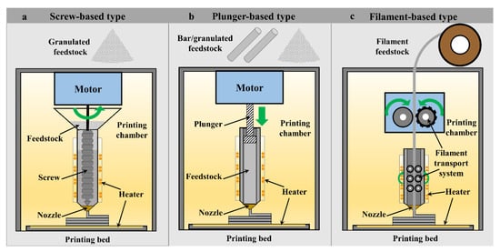
Figure 3. Types of material extrusion additive manufacturing classified by feeding system: (a) screw-based, (b) plunger-based and (c) filament-based types.
-
Screw-based MEX (SB)
High quality metal filament and bar feedstocks are still very limited in alloy selection. Hence, screw-based MEX is currently the most versatile material extrusion system in term of material selection. Screw-based MEX uses the granulated feedstock in a similar form as MIM, hence all alloys for MIM feedstocks are applicable. The feedstock will be transported by screw rotation [132] and simultaneously heated by heating elements to a temperature above the glass transition temperature of the polymer binder. The softened material will be deposited through the nozzle in a pattern that follows the CAD design, as presented in Figure 3a. The advantages of this type over the latter two processes, which are plunger- (Figure 3b) and filament- (Figure 3c) based types are high productivity due to a continuous filling system and no requirement for an additional processing step for bar or filament preparation. In addition, high solid loading equivalent to that employed in MIM can be used. This process provides the best available feedstock filling system, which can continuously feed without interruption during printing, as the feedstock in the system is replenished. This results in printing time reduction, as neither printing stoppage during feedstock replenishment nor feedstock re-heating to the printing temperature is mandatory. There is also no need for additional equipment for bar or filament preparation and know-how to produce and handle feedstocks, especially filament feedstock, which is commonly brittle and difficult to handle. The size of the granulated feedstock needs to be controlled (<5 mm) to obtain stability during printing and reduce printing defects generated by air entrapment [133]. As reported by Singh et al. [85], the granule feedstock, sized from 3 to 5 mm, can provide relative sintered density up to 94% after sintering. Likewise, Lieberwirth et al. [41] reported that a granule size of 3 mm could be readily printed, yielding good appearance. Too large granulated feedstock may not be evenly and properly softened in the feeding system. Too small granulated feedstock may cause blocking at the hopper. Any printed mono-material green parts with defects or mistakes can be easily re-used by crushing and sieving before feeding back into the printer hopper, similar to the re-use of MIM injected parts with defects and all runner systems [134]. The other two types of printing systems need an additional bar or filament preparation step. The stabilisation of the screw system is still challenging to fabricate the 3D part, as it is difficult to control the flow rate of the material to be constant due to the trapped air inside the softened material. Moreover, the strength and stability of the printing system are also required during printing due to the high viscosity of the feedstock. The well-known commercially available screw-based MEX systems are proposed by AIM3D GmbH with a “ceramic extrusion modelling” system (CEM) [135] and Pollen AM, Ltd. With a “pallet additive manufacturing” system (PAM) [136], in which multi-material parts, such as both ceramic and metal, can be fabricated by using general powder injection moulding feedstocks. Figure 4a shows the AIM3D printer and the schematic representing the printing, while Figure 4b shows the feedstock and the microstructure of the feedstock utilised for the AIM3D printer. Recently, pallet extrusion system has been introduced by Direct3D, which supplies both a screw-based printer and only a screw-based print head that can be applied with a suitable 3D printer [137]. In addition, most MIM manufacturers will prefer to use their current MIM feedstock so that they can use their current debinding and sintering systems. Hence, the implementation of metal MEX will be easier, smoother, faster and more economical for MIM manufacturers.
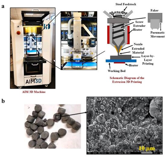
Figure 4. (a) AIM3D printer and the schematic representing the printing and (b) low and high magnification of the 17-4PH stainless steel granulated feedstock utilised for the printer [92].
-
Plunger-based MEX (PB)
The plunger-based MEX utilises bar or granulated feedstock to feed to the nozzle of the plunger system. Desktop Metal, Inc. [138] proposes the plunger-based system using circular-bar feedstock, called “bound deposition modelling” (BMD), in which the bar feedstock will be fed by a cartridge into a heated sleeve. The feedstock is then pushed through the nozzle for layer-by-layer printing by the plunger following the CAD design as presented in Figure 3b. One of the main advantages of this system is the high material handling ability, which is significantly easier than the filament feedstock. Besides, the solid loading of the bar feedstock can be higher than the filament-based printers and comparable to the MIM feedstock. However, one of the main disadvantages of the plunger-based system when compared to the screw-based one is the additional step of bar feedstock preparation. The bar feedstock can be prepared by extruding the mixture of metal powder and polymer binders and cut to size, as shown in Figure 2a. Furthermore, print discontinuity occurs when the feedstock is required to be replenished. To overcome this disadvantage, Giberti et al. proposed an in-house developed machine, as shown in Figure 5a, combining a screw-based to feed the MIM feedstock and plunger system to push the feedstock through the nozzle [36]. However, at the end of the plunger stroke, the plunger still requires reversing to receive the softened feedstock from the screw-based plasticiser. Hence, the discontinuity is minimised but remained. As the injection unit is stationary, the deposited path will be printed on the printing bed of a 5-axes parallel kinematics machine (PKM). Hence, parts can be printed with minimal support materials. In 2020, Waalkes et al. proposed an in-house plunger-based printer, as presented in Figure 5b, which can fabricate the 3D part of Ti-6Al-4V using commercial MIM feedstock [61]. This in-house system successfully fabricates the as-printed parts with a good appearance and high stability. Moreover, the production cost of the machine is claimed to be close to the open polymer filament-based systems (5–10 k€) [61]. These in-house developed plunger-based printers provide the ability to use MIM feedstock. This increases the flexibility in material selection. In addition, there is no need for further feedstock preparation into filament form.
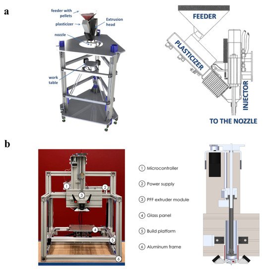
Figure 5. (a) In-house developed machine and their components with the extrusion unit combining a screw-based (plasticiser) to feed the feedstock and plunger system to inject the feedstock through the nozzle [36] and (b) in-house developed plunger-based printer and their components with the schematic of the extruder unit [61].
-
Filament-based MEX (FB)
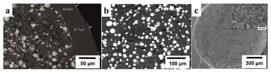
Filament-based type is the most popularly and widely used metal MEX process. It is known by many terms, such as “fused deposition modelling” (FDM), first developed by Stratasys, Ltd. (Eden Prairie, MN, USA and Rehovot, Israel) for polymer [139]; “fused filament fabrication” (FFF) or “atomic diffusion additive manufacturing” (ADAM) proposed by Markforged, Inc., Watertown, MA, USA [140]. At the beginning, this process was usually used for rapid prototyping; however, it can currently be used for tooling and end-user part fabrication [50,140,141]. The filament of metal MEX composed of the metal powder and polymeric binder is fed by the filament transport system to the heating element and heated nozzle so that the filament will be softened and extruded to the printing bed layer-by-layer following the CAD design as illustrated in Figure 3c. The advantages of this filament-based process are safety, simplicity and familiarity of the process, and its low-cost equipment because the general desktop polymer 3D printer is used with the metal MEX filament. The high volume fraction of metal in the filament results in a high wear rate of the printing nozzle; hence, a special ruby or hardened steel nozzle should be utilised to produce a stable flow of the filament, prolong the nozzle life [142] and reduce contamination. The main disadvantage of this process is the need for filament production, which requires single/twin screws or plunger extrusion equipment for filament fabrication [34,52], plus special know-how, e.g., the selection of appropriate binder types, suitable mixing procedure and the filament fabrication technique [31]. The filament properties are very important to the final shape, size, dimension and properties in both as-printed and as-sintered stages. Appropriate binders must be selected to provide the desired properties in the filament. The filament should have high strength and stiffness so that the filament can be driven by the roller or gear without breaking and bulking [31,143,144]. The high bonding strength of the metal powder and binders of the filament can provide strong weldability between deposit paths. In addition, the filament should have high flexural strength and stiffness so that the filament can be spooled and handled with ease [31]. The filament will be brittle if too-high solid loading is used [145]. Very careful handling of the filament is needed with an extra heater to reduce the brittleness of the filament and to reset the memory shape [56,64,146]. The filament must have no porosity, shape consistency and uniform distribution of the metal powder, including as high as possible of solid loading to minimise shrinkage [94]. The above factors directly influence the printing, debinding and sintering processes, which can be prone to generate many defects. High quality sintered parts can be achieved if these factors and the processes are correctly controlled. Examples of commercially available filaments are Ultrafuse 316L® by BASF SE [147], Filamet® by Virtual foundry [146] and 316L metal filament by Anycubic [148], which provide high-quality metal filaments, together with the suggested suitable range of processing parameters. The cross section of commercially available filament by BASF (Figure 6a), Virtual foundry (Figure 6b), including the filament specially developed for MetalX by Markforded, Inc. (Figure 6b) shows high fraction of the metal powder. It is noted that the Ultrafuse 316L filament uses polymer skin (Figure 6a) to case the filament to increase the flexibility of the filament [4], while the Filamet and Anycubic filament use binder with high flexibility and lower solid loading [48,146].
This entry is adapted from the peer-reviewed paper 10.3390/met12030429
This entry is offline, you can click here to edit this entry!