Your browser does not fully support modern features. Please upgrade for a smoother experience.
Please note this is an old version of this entry, which may differ significantly from the current revision.
The compound parabolic concentrating (CPC) collectors belong to a class of concentrators called non-imaging concentrators. These concentrators allow the design of optical systems that can attain maximum geometric concentrations permitted by laws of physical conservation for a given angular field. As opposed to imaging or focusing concentrators, the concentrators based on non-imaging optics are capable of achieving moderate levels of concentration without tracking the sun.
- acceptance half-angle
- building integrated concentrating photovoltaic/thermal
- ray tracing
1. Historical Perspective
Optical concentrators are used in both solar thermal collectors and solar PV converters. However, the motivation for using optical concentrators is different for two major classes of solar energy collectors. For solar thermal collectors, the key aspiration for employing concentrators is to elevate the performance at higher operating temperatures by reducing the heat losses due to a relatively smaller absorber area. Conversely, the major motivation for using optical devices in solar PV converters is the economic benefit achieved due to reduced solar cell area owing to the concentration of solar irradiation [1]. The silicon solar cell is the most expensive part of a solar PV-based electricity generation system which prohibits the widespread use of PV generators to fulfill domestic and industrial electrical load requirements [2]. However, the costly solar cells can be replaced by relatively cheaper optical concentrators to render the solar PV generators cost-effective.
After initial investigations in the USA during the 1970s, the technical feasibility and economic viability of CPCs for PV applications had been established. To further reinforce this, Mallick et al. [3] conducted an experimental one in the UK employing an asymmetric CPC of 2.0× concentration to demonstrate that maximum generated power increases by 62% due to CPC. Yousef et al. [4] conducted a performance assessment of a PV module integrated with 2.4× CPC for climatic conditions of Egypt using experimental and numerical methods. Their results indicated that the peak power produced by the CPC-based PV module increased by 18% compared to analogous non-concentrating PV modules. It was also reported an increment of 32% in the short-circuit current. Nonetheless, the open-circuit voltage declined by 5% due to high temperature. The next research phase started to eradicate the problems observed during the first phase with different goals. Various groups and individual researchers investigated CPC-PV systems with versatile research objectives. For example, it was proposed novel designs of CPCs for PV systems and conducted research to investigate their optical performance. In contrast, others explored the varieties of solar cells employed in the PV receiver, including monocrystalline, polycrystalline, or thin-film solar cells. Some others were devoted to the issue of non-uniform illumination of the receiver and how to mitigate its impact on the system’s performance.
2. Basic Construction and Classification of CPCs
The CPC collectors belong to a class of concentrators called non-imaging concentrators. These concentrators allow the design of optical systems that can attain maximum geometric concentrations permitted by laws of physical conservation for a given angular field. As opposed to imaging or focusing concentrators, the concentrators based on non-imaging optics are capable of achieving moderate levels of concentration without tracking the sun. Non-imaging optical concentrators are designed based on the edge ray principle, which asserts that sun rays emanating from the verges of the source are focused on the verges of the target surface [1]. Thus, all rays lying within a given acceptance angle have a chance to reach the receiver.
In its simplest form, the CPC consists of two parabolic reflecting segments that direct the sunrays arriving at the entrance aperture to a receiver surface positioned at the leaving aperture [5]. The left and right segments of CPC are parts of two parabolas, while the receiver is placed between the focus points of these parabolas. The axes of the parabolic segments are orientated away from the CPC axis by an angular range, known as an acceptance half angle, as illustrated in Figure 1. The solar radiation falling within this angular range of CPC would travel all the way to reach the receiver, directly or after one or more reflections [6][7][8].
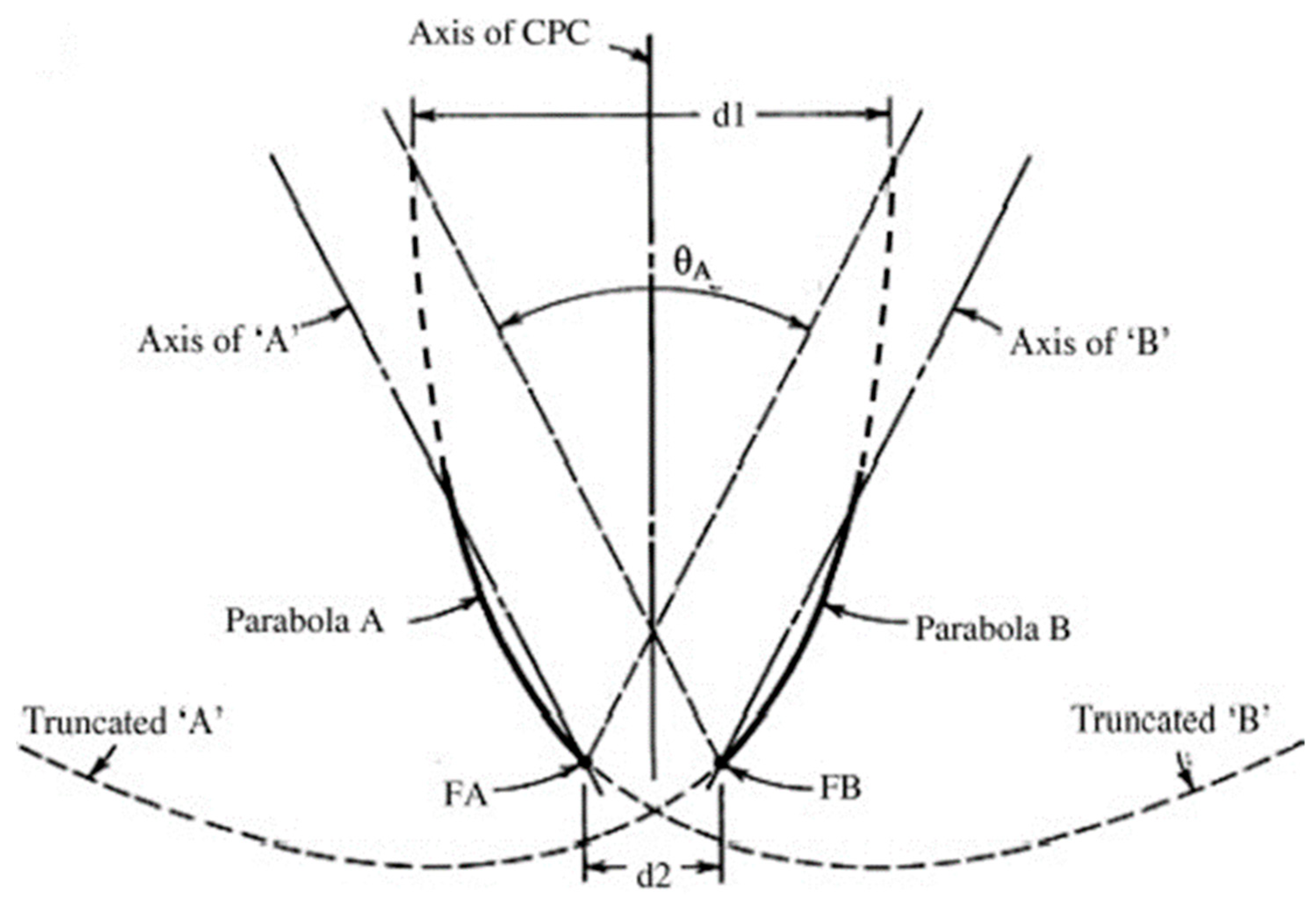
Figure 1. Profile of a symmetric 2D CPC [9].
The design process of an ideal CPC starts with specifying the values of acceptance half angle and width of the flat receiver. The resulting width of the entry aperture and total height of CPC are then calculated using the equations derived by Winston and his fellow researchers [10][11]. Afterward, the set of coordinates for one of the parabolic reflectors in the Cartesian coordinate system is determined [12]. The other side parabolic reflector is simply the mirror image of its counterpart [1] in a symmetric CPC. Some researchers have developed a new set of equations for designing a symmetric CPC having a flat receiver, for example, Taneja et al. [13], Fraidenraich and Salcedo [14], and Tiruneh [15]. Paul [16] presented a detailed one of mathematical equations used to design different symmetric and asymmetric CPC collectors configurations for solar energy applications.
The CPCs are generally categorized as either two-dimensional (2D) and three-dimensional (3D) or symmetric and asymmetric types [17]. The 2D CPC has a cylindrical trough-like shape formed by translating the primary geometry perpendicular to the page, whereas the 3D CPC is obtained by rotating a 2D CPC around its axis of symmetry. The symmetric 2D CPC is the basic CPC geometry, while all other variants can be derived from this basic shape [18]. The classification of CPCs is shown in Figure 2. While the concentration ratio of a symmetric CPC is fixed for all incidence angles within its acceptance angle range, an asymmetric CPC possesses a variable concentration ratio due to the fact that the acceptance half angles for left and right parabolic reflectors are not the same [19]. That is why it is not geometrically symmetric around its central axis. A 3D CPC causes increments in the geometrical concentration ratio compared to 2D CPC, due to which the size of solar cells is further reduced for a given output. However, the circular shape of entry and exit apertures of 3D CPC acts as a source of losses. Moreover, the circular shape of 3D CPC also causes hurdles in its integration with commercially available square-shaped silicon solar cells. To overcome the limitations of 3D CPC, a modified circular 3D CPC, crossed CPC, having square acceptance and exit apertures was proposed [20].
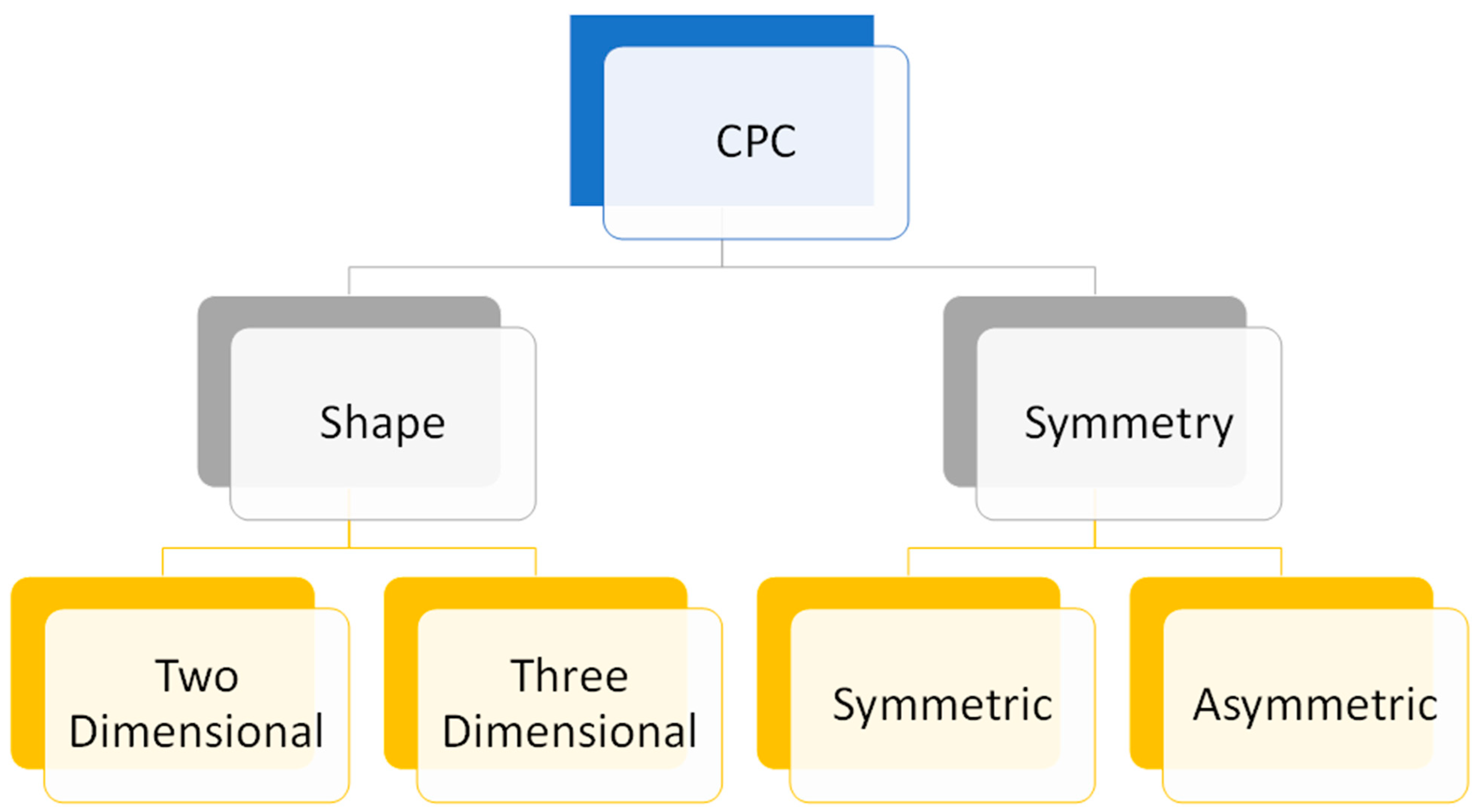
Figure 2. Classification of CPCs w.r.t. shape and symmetry.
The economic feasibility of a CPC collector is dependent on its manufacturing cost, which is directly related to the area of reflecting surfaces. One weakness of basic CPC design is its relatively larger height in comparison to the width of the receiver surface. This problem can be solved by removing the portions of CPC parallel to its optical axis as they are contributing very little to the size of the entry aperture and concentration ratio [7][17]. The process of removing these least contributing portions without significantly reducing the acceptance half angle and hence the solar radiation collection by the concentrator is known as truncation. Truncation reduces CPC height, thus causing a reduction in total mirror area and the manufacturing cost. Truncation also causes a reduction in the number of reflections of incident rays before reaching the destination. About 50% truncation of full height offers a good agreement between CPC’s concentration and mirror area [1]. Carvalho et al. [21] appraised the effect of truncation position on the monthly and annual average energy collected by 2D CPCs, taking into account the optical and thermal losses. It was developed analytical equations for calculating the angular acceptance to observe the impact of truncation on the CPC field of view. Higher receipt of the beam and diffuse radiation and lower mean number of reflections were reported to be the optical gains resulting from truncation.
3. Feasibility of CPC-Based Hybrid PVT Systems
A PVT system is a hybrid arrangement consisting of a thermal receiver combined with a PV module to remove the heat produced in the PV cells during the photovoltaic conversion process to lower their temperature and increase conversion efficiency. A hybrid PVT collector has the capability of simultaneously generating both electricity and heat. The schematic diagram of the CPC-PVT collector is illustrated in Figure 3. Diverse configurations of hybrid PVT systems are available [22][23][24][25]. Huang et al. [26] assessed the performance of an integrated PVT system consisting of a commercially available polycrystalline PV unit and a heat-gathering sheet. It was demonstrated that the principal energy-saving efficacy of the integrated system was superior to that of an equivalent-sized traditional solar water heating system and PV panel working individually. The performance of a hybrid PVT system can be proficiently augmented by integrating optical elements with it. It was revealed that heat produced by a concentrating PVT system is always at higher temperatures than its non-concentrating or flat plate counterpart due to the concentration of sunlight on the PV surface and can be potentially used in low to medium temperature thermal applications [27]. Consequently, the quality of heat energy produced by a concentrating hybrid PVT system is superior due to the presence of an optical concentrating element within the hybrid system.
Zhang et al. [28] presented the design and performance estimation of a 4× CPC-based LCPVT system using simulations and experiments. It was attached a baffle heat exchange channel at the back of PV cells to reduce the temperature gradient along the flow direction of the coolant. The performance of the proposed system was assessed by varying the baffle spacing, flow rate, solar irradiance, and inlet and ambient temperatures. The maximum thermal and electrical efficiencies on a typical day were recorded to be 55.11% and 12.5%, respectively. The performance comparison between low concentration and conventional hybrid PVT collectors can potentially reveal the benefits of low concentration PVT systems. In another study, Zhang et al. [29] compared the electrical and thermal performances of an LCPVT system, having a CR of 4×, with a typical flat plate hybrid receiver for climatic conditions of China. The comparison was made for fixed mass flow rate conditions. It was experimentally proved that the LCPVT module generated three times more electrical power and approximately two times more thermal power compared to an equivalent nonconcentrating PVT module. As a result, CPC collectors have emerged as a preferred choice for researchers working in the field of hybrid LCPVT systems. To prove this, some authors have studied the benefits of integrating different CPC designs with PVT collectors.
Bahaidarah et al. [30] evaluated the impact of cooling on the performance of nonconcentrating and CPC-based concentrating PV modules. It was demonstrated that cooling enhanced the output power by 49% and 100% for nonconcentrating and CPC-based concentrating PV modules, respectively. The heat energy extracted from the concentrated receiver can be used in low-temperature thermal applications causing an increment in the overall performance of the LCPV system. Yousef et al. [28] conducted a similar comparative performance evaluation for Egypt’s hot and arid climatic conditions. It was noticed that the temperatures of nonconcentrating and CPC-based concentrating PV systems were lowered by 25% and 30%, respectively, causing significant increments in the output power of both systems. Moreover, the CPC-based PV system generated 52% more power in comparison with the flat PV module when the cooling mechanism was employed. Thus, the cooling causes dual benefits by increasing the electrical performance and simultaneously providing valuable thermal energy.
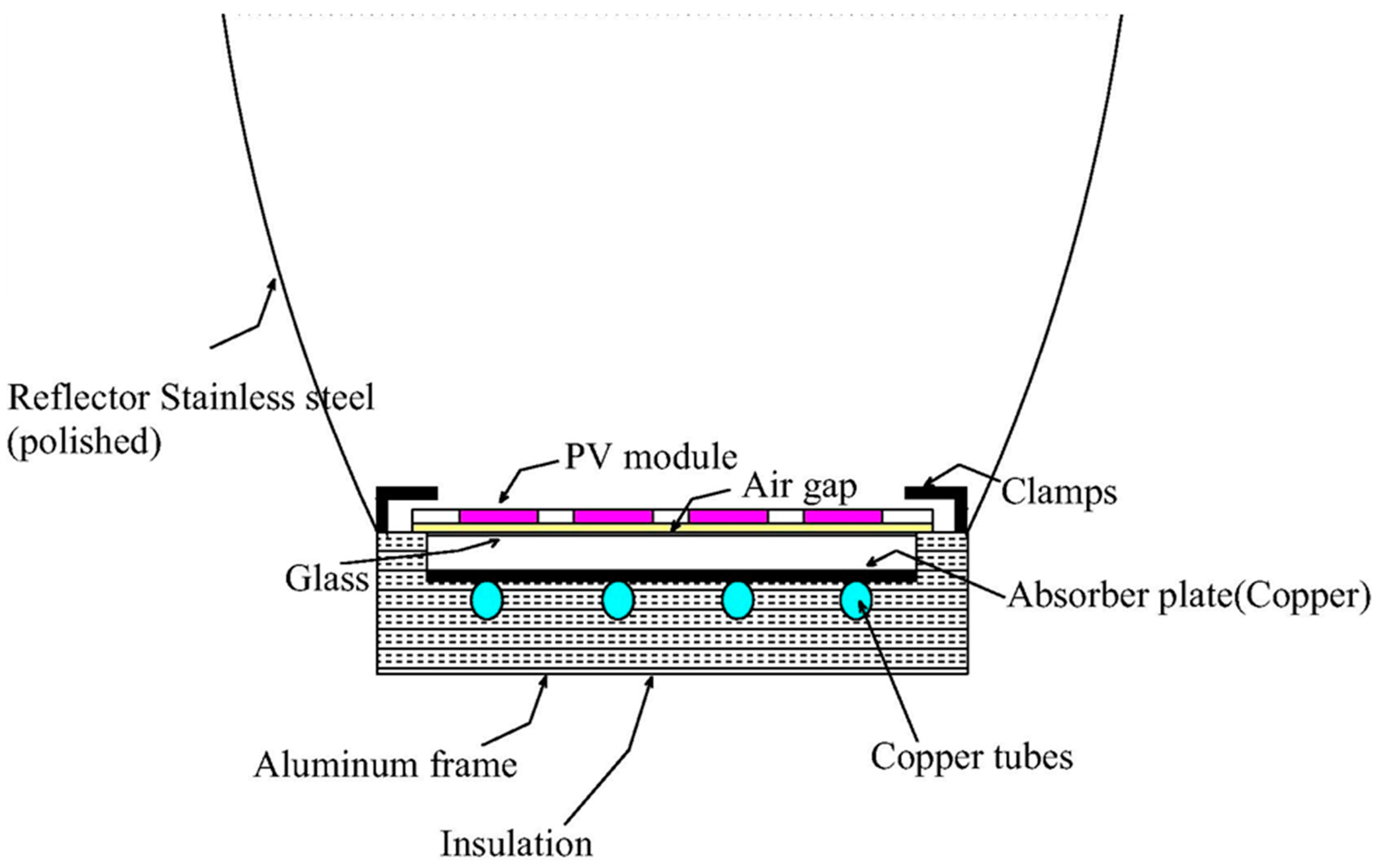
Figure 3. A Sketch of CPC-based PVT System [31].
4. Performance Enhancement Using Phase Change Materials
The phase change materials (PCM) can absorb and disperse substantial amounts of latent heat during the transformation in their physical condition. Therefore, the integration of PCM with the PVT systems offers dual benefits of PV cooling and storage of thermal energy. Al-Imam et al. [32][33] used PCM for improving the performance of the CPC-PVT system for the climatic conditions of Bangladesh. It was [32] conducted experimental investigations on clear sky and semi-cloudy days using a CPC integrated PVT collector fitted with a tank having PCM for energy storage. The thermal efficiency was found to vary from 40 to 50% and around 40% on clear sky and semi-cloudy days, respectively, whereas the overall efficiency varied between 55–63% and 46–55% for clear sky and semi-cloudy weather conditions. It was concluded that the integration of CPC and PCM caused an increment in the performance of hybrid PVT system.
Liu et al. [34] numerically estimated the performance of a CPC-based PVT collector utilizing a microencapsulated phase change effluent as the cooling agent. The proposed system’s electrical and thermal efficiencies attained their peak values when the solar radiation was at minimum. A comparative one of the cooling performance of the water and microencapsulated phase change effluent was conducted. It was suggested that the thermal and electrical efficiencies were incremented by 9.24% and 1.8%, respectively, due to the proposed cooling method.
This entry is adapted from the peer-reviewed paper 10.3390/su14095529
References
- O’Gallagher, J.J. Nonimaging Optics in Solar Energy. Synth. Lect. Energy Environ. Technol. Sci. Soc. 2008, 2, 1–120.
- Zahedi, A. Review of modelling details in relation to low-concentration solar concentrating photovoltaic. Renew. Sustain. Energy Rev. 2011, 15, 1609–1614.
- Mallick, T.K.; Eames, P.C.; Hyde, T.J.; Norton, B. The design and experimental characterisation of an asymmetric compound parabolic photovoltaic concentrator for building façade integration in the UK. Sol. Energy 2004, 77, 319–327.
- Yousef, M.S.; Nada, S.A.; Ookawara, S. Performance Evaluation of Photovoltaic panel Integrated with Compound Parabolic Concentrator (CPC) Installed in Hot Arid Area. In Proceedings of the 14th International Conference on Sustainable Energy Technologies—SET 2015, Nottingham, UK, 25–27 August 2015.
- Masood, F.; Nallagownden, P.; Elamvazuthi, I.; Akhter, J.; Alam, M.A. A New Approach for Design Optimization and Parametric Analysis of Symmetric Compound Parabolic Concentrator for Photovoltaic Applications. Sustainability 2021, 13, 4606.
- Hinterberger, H.; Winston, R. Principles of cylindrical concentrators for solar energy. Sol. Energy 1975, 17, 255–258.
- Rabl, A. Optical and thermal properties of compound parabolic concentrators. Sol. Energy 1976, 18, 497–511.
- Masood, F.; Nor, N.B.M.; Nallagownden, P.; Elamvazuthi, I.; Alam, M.A.; Yusuf, M.; Ali, M.; Akhter, J.; Mehmood, M. Dataset on the effect of receiver size and acceptance half-angle on the aperture width and height of compound parabolic concentrator for low-concentrating photovoltaic applications using RSM. Data Brief 2021, 39, 107630.
- Gudekar, A.S.; Jadhav, A.S.; Panse, S.V.; Joshi, J.B.; Pandit, A.B. Cost effective design of compound parabolic collector for steam generation. Sol. Energy 2013, 90, 43–50.
- Winston, R.; Minano, J.C.; Benitez, P.G.; Bortz, W.N.S.J.C.; Shatz, N.; Bortz, J.C. Nonimaging Optics; Elsevier: Amsterdam, The Netherlands, 2005.
- Rabl, A.; Sevcik, V.J.; Giugler, R.M.; Winston, R. Use of Compound Parabolic Concentrator for Solar Energy Collection, 3rd ed.; Argonne National Lab.: Lemont, IL, USA, 1974.
- Rabl, A.; Winston, R. Ideal concentrators for finite sources and restricted exit angles. Appl. Opt. 1976, 15, 2880–2883.
- Taneja, P.; Kandpal, T.; Mathur, S. Concentration characteristics of a two stage solar concentrator: Effect of primary mirror surface errors. Int. J. Energy Res. 1992, 16, 203–211.
- Fraidenraich, N.; Salcedo, I.H. Multimode analysis of compound parabolic concentrators with flat absorber. Appl. Opt. 1993, 32, 2891–2900.
- Tiruneh, A.T.; Ndlela, W.N.; Gadaga, T.H.; Debesay, T.; Heikkilä, J. A Four-Wing Compound Parabolic Concentrator (CPC) Design for Heating and Sanitization of Waste Products. J. Power Energy Eng. 2017, 5, 18–35.
- Paul, D.I. Review of Mathematical Equations for the Design of Compound Parabolic Concentrating Solar Energy Collectors. Invertis J. Renew. Energy 2019, 9, 91.
- Rabl, A. Comparison of solar concentrators. Sol. Energy 1976, 18, 93–111.
- Winston, R. Principles of solar concentrators of a novel design. Sol. Energy 1974, 16, 89–95.
- Zanesco, I.; Lorenzo, E. Optimisation of an asymmetric static concentrator: The PEC—44D. Prog. Photovolt. Res. Appl. 2002, 10, 361–376.
- Sellami, N.; Mallick, T.K. Optical efficiency study of PV Crossed Compound Parabolic Concentrator. Appl. Energy 2013, 102, 868–876.
- Carvalho, M.; Collares-Pereira, M.; Gordon, J.; Rabl, A. Truncation of CPC solar collectors and its effect on energy collection. Sol. Energy 1985, 35, 393–399.
- Sarhaddi, F.; Farahat, S.; Ajam, H.; Behzadmehr, A.; Mahdavi Adeli, M. An improved thermal and electrical model for a solar photovoltaic thermal (PV/T) air collector. Appl. Energy 2010, 87, 2328–2339.
- Preet, S. Water and phase change material based photovoltaic thermal management systems: A review. Renew. Sustain. Energy Rev. 2018, 82, 791–807.
- Michael, J.J.; Iniyan, S.; Goic, R. Flat plate solar photovoltaic–thermal (PV/T) systems: A reference guide. Renew. Sustain. Energy Rev. 2015, 51, 62–88.
- Guarracino, I.; Mellor, A.; Ekins-Daukes, N.J.; Markides, C.N. Dynamic coupled thermal-and-electrical modelling of sheet-and-tube hybrid photovoltaic/thermal (PVT) collectors. Appl. Therm. Eng. 2016, 101, 778–795.
- Huang, B.; Lin, T.; Hung, W.; Sun, F. Performance evaluation of solar photovoltaic/thermal systems. Sol. Energy 2001, 70, 443–448.
- Riffat, S.B.; Cuce, E. A review on hybrid photovoltaic/thermal collectors and systems. Int. J. Low-Carbon Technol. 2011, 6, 212–241.
- Zhang, H.; Chen, H.; Liu, H.; Huang, J.; Guo, X.; Li, M. Design and performance study of a low concentration photovoltaic-thermal module. Int. J. Energy Res. 2018, 42, 2199–2212.
- Zhang, H.; Liang, K.; Chen, H.; Gao, D.; Guo, X. Thermal and electrical performance of low-concentrating PV/T and flat-plate PV/T systems: A comparative study. Energy 2019, 177, 66–76.
- Bahaidarah, H.M.; Tanweer, B.; Gandhidasan, P.; Ibrahim, N.; Rehman, S. Experimental and numerical study on non-concentrating and symmetric unglazed compound parabolic photovoltaic concentration systems. Appl. Energy 2014, 136, 527–536.
- Atheaya, D.; Tiwari, A.; Tiwari, G.N. Experimental validation of a fully covered photovoltaic thermal compound parabolic concentrator system. Eng. Sci. Technol. Int. J. 2016, 19, 1845–1856.
- al Imam, M.F.I.; Beg, R.A.; Rahman, M.S.; Khan, M.Z.H. Performance of PVT solar collector with compound parabolic concentrator and phase change materials. Energy Build. 2016, 113, 139–144.
- al Imam, M.; Beg, M.R.A.; Rahman, M. Experimental Analysis on the Photovoltaic-Thermal Solar Collector with Compound Parabolic Concentrator Using Phase Change Material-Towards Solar Energy Utilization. J. Eng. Sci. Technol. 2018, 13, 3964–3979.
- Liu, L.; Jia, Y.; Lin, Y.; Alva, G.; Fang, G. Numerical study of a novel miniature compound parabolic concentrating photovoltaic/thermal collector with microencapsulated phase change slurry. Energy Convers. Manag. 2017, 153, 106–114.
This entry is offline, you can click here to edit this entry!