Your browser does not fully support modern features. Please upgrade for a smoother experience.
Please note this is an old version of this entry, which may differ significantly from the current revision.
Doubly fed induction generators (DFIGs) are the most widely used generators in wind turbines. However, due to the incessant failures of their slip rings and brushes, the operating and maintenance costs of DFIG based wind turbines are high; this is even worse in remote areas like offshore wind sites. Research interest on brushless doubly fed induction machines (BDFMs) is increasing, as they offer higher reliability compared to doubly fed induction generators (DFIGs) in wind turbines.
- wind power generation
- brushless doubly fed machines
- pole pair combinations
1. Stator Winding Development
Up until around 1989, the L.J. Hunt type of stator windings [1] were used for brushless doubly fed machines (BDFMs), in which coil groups were interconnected in a way to accommodate two AC supplies (or pole pairs) [2]. However in [3], it was suggested that the L.J. hunt type of stator winding was better suited for applications in which only one set of terminals were connected to a power source at a time.
For synchronous BDFM operations, with two AC supplies connected to the terminals, there are unbalances in the Hunt type of stator, which lead to internal circulating currents. Therefore, reverting to isolated stator windings like in the Lydall motor was recommended in [3]. This helped in avoiding the circulating currents, while affording greater simplicity and flexibility.
Consequently, contemporary BDFM stators have two isolated windings, the power winding (PW) and the control winding (CW). The stator windings do not couple directly, but are cross-coupled by a special rotor. As already suggested in [4], the winding which is farthest from the airgap has increased leakage. Placing the PW at the bottom layer would have significant effects on the converter ratings, as higher leakage would increase the difficulty in controlling the grid side power factor as noted in [5]. Thus, the PW with p1 pole pairs typically occupies the bottom layer (closest to the airgap) of the stator slots, while the CW with p2 pole pairs occupies the top layer. This type of stator for a= p1/p2 = 2/3 BDFM, is illustrated in Figure 1.
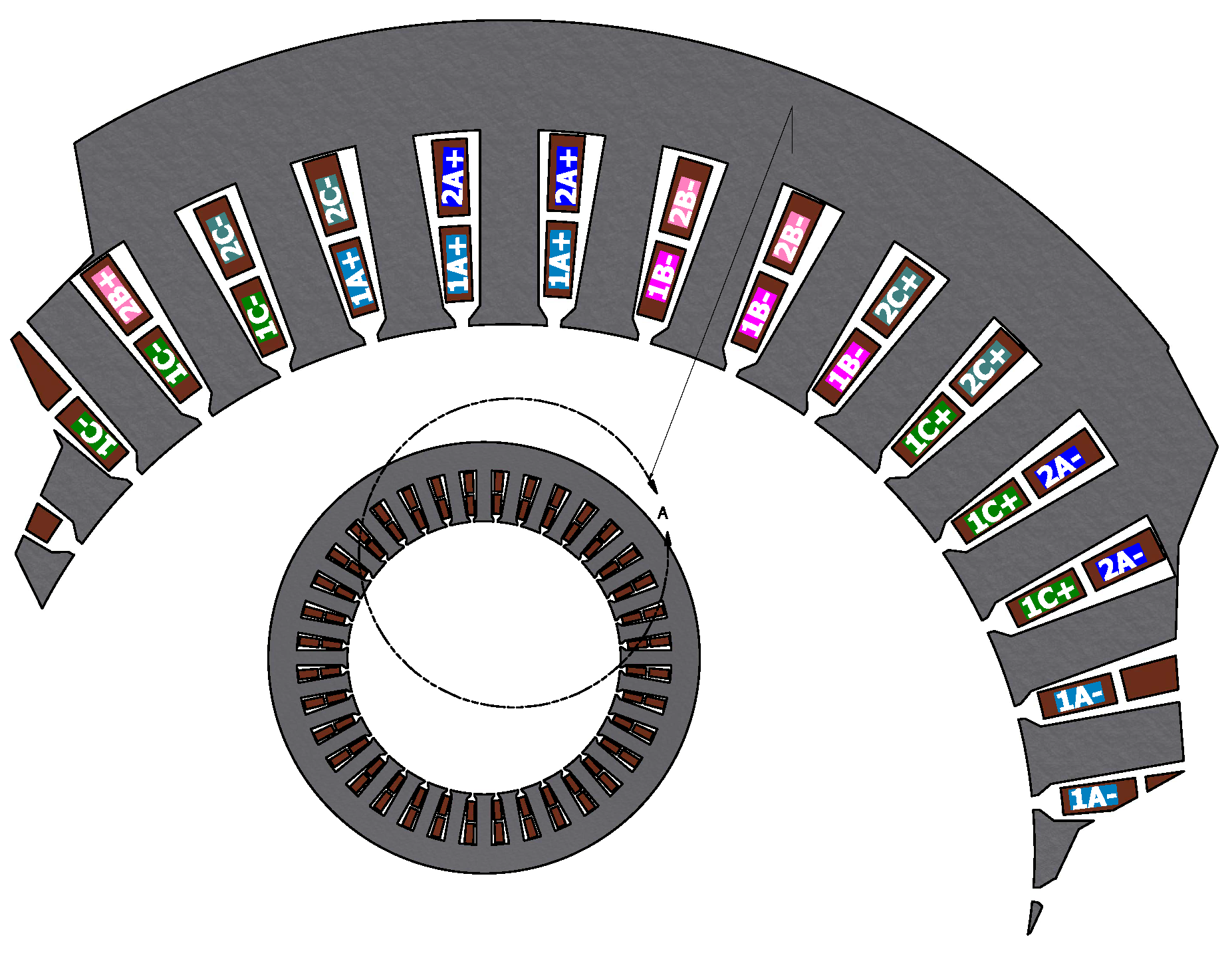
Figure 1. Stator winding arrangement of a BDFM with p1/p2=2/31/p
2. Rotor Winding Development
The nested loop (NL) and cage+NL rotors, whose origins are traced to [6], are currently deemed the most suitable for BDFMs [7][8][9]. The NL rotor winding arrangement and a prototype are shown in Figure 2a,b respectively. The cage+NL rotor winding arrangement has already being illustrated in Figure 1b, and a prototype is shown in Figure 2c. The winding arrangement in Figure 2a differs from that in Figure 1a by the presence of a common end ring, with the rotor illustrated in Figure 1a now sometimes called an isolated loop (IL) rotor [8]. These (NL, IL, & cage+NL) rotor types have robust builds with better torque performance and lower losses, compared to wound rotors [7].
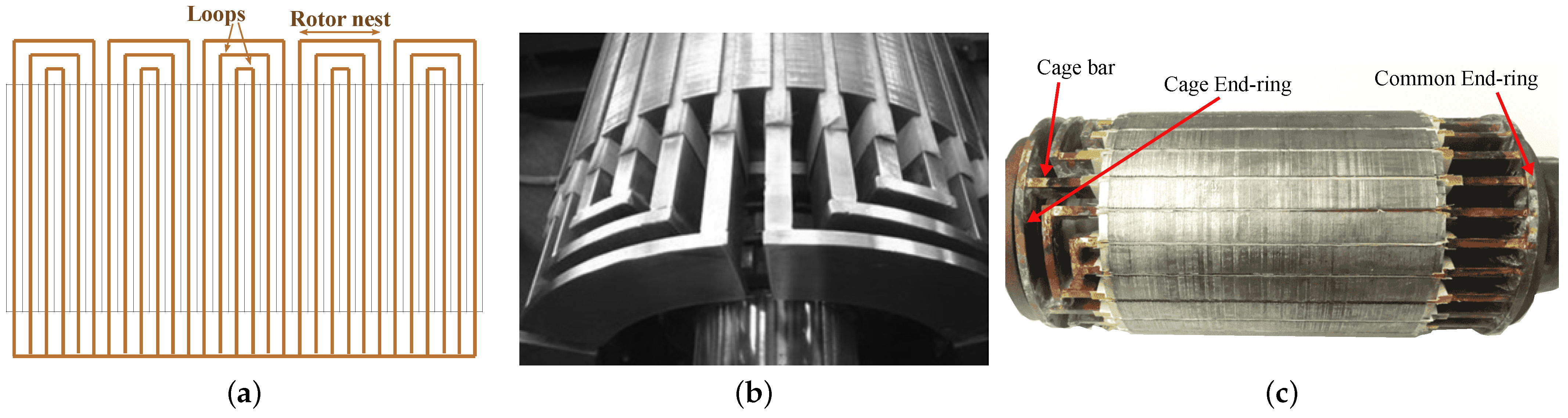
Figure 2. Widely used BDFM rotors: (a) NL rotor winding arrangement for p1+p2 = 5(b) NL rotor prototype [9], and (c) Cage + NL rotor prototype.
A rotor similar to the NL rotor, but with double layers of bars, is highlighted in [8]. It is suggested that this double layer bar rotor has a larger torque envelope than the NL rotor; also higher efficiency due to less excess harmonic reactance. However, the increased complexity has manufacturing and control implications. The double layer bar rotor winding arrangement is illustrated in Figure 3a, while a prototype is shown in Figure 3b.
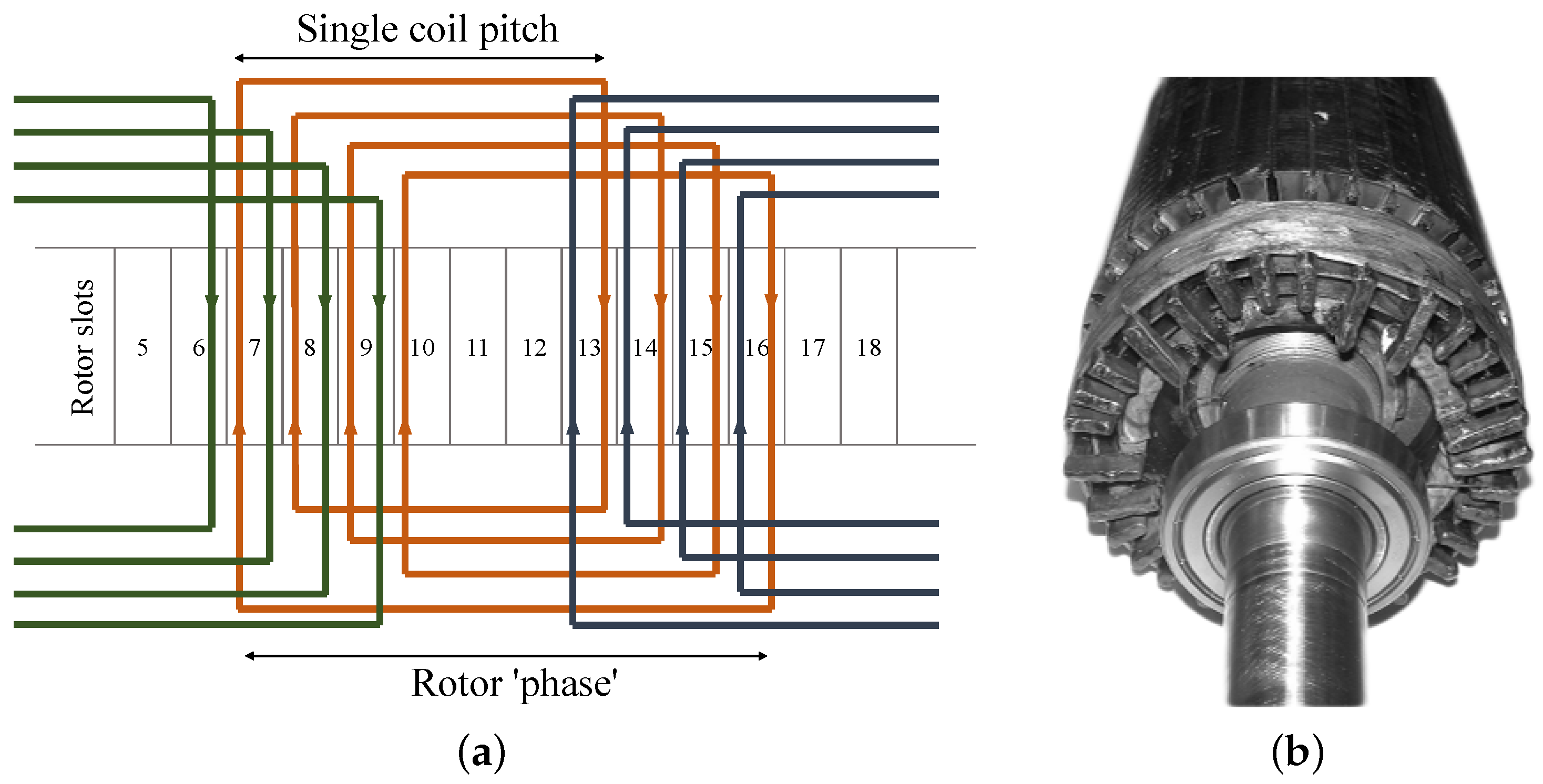
Figure 3. Double layer bar rotor: (a) Winding arrangement for p1/p2=2/4 and (b) prototype [8].
Whilst considering the high harmonic reactance and potential considerable skin effect in large BDFMs using NL rotors, series wound (SW) rotors are compared with NL rotors in [9]. The winding arrangement of the SW rotor is illustrated in Figure 4a, with a prototype shown in Figure 4b. Although the SW rotor has lower harmonic content and no skin effect issues, it has higher impedance and develops lower torque. Despite this, the performance of the SW rotor is deemed acceptable. It is also indicated that with similar slot fill factors, the SW and NL rotors will have similar torque performance due to identical referred rotor resistance. Also in [10], details of the design of a 60 kW BDFM with a special “double-sine” rotor are given. This rotor was designed as a potential BDFM rotor with greatly reduced harmonic content.
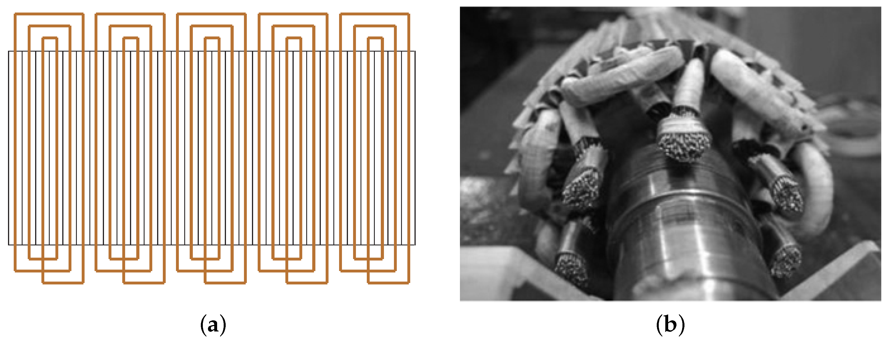
Figure 4. SW rotor: (a) Winding arrangement for p1+p2 = 5 and (b) prototype [9].
Although, the cage+NL rotor has similar advantages with the NL rotor, the NL configuration is more commonly used [7]. In [11][12], the NL and cage+NL rotors are compared based on their rotor equivalent circuit parameters, and it is suggested that the cage+NL rotors provide better performance due to their lower impedances.
Initial guidelines for loop design of the NL and cage+NL rotors are given in [13]. It is suggested that loops with spans closer to the pitch of the higher pole number in the BDFM, are more efficient and effective in torque production. It is also suggested in [13], that loops with small spans have minor contributions to torque production, similar to suggestions in [11][14][15].
Observations in [11][13][14] indicate that the rotor loops should not necessarily be evenly spaced, and the width of the outer loops should be maximized. An increase in rotor loops per nest helps to mitigate space harmonics in BDFMs [14][16], and helps with better current distribution in BDFM rotors [16].
3. BDFM Sizing and Power Ratings
By analyzing the stator magnetic fields in BDFMs using a per phase equivalent circuit, a composite magnetic loading based on the stator fields is derived in [17]. Expressions for the BDFM power rating as a function of the pole pairs, stack length, airgap radius, electric and magnetic loadings, are given in [17]. The magnetic loading derivation in [17] was further modified in [16], as the loading derived in [17] was deemed too conservative, leading to over-sizing. Other aspects of the BDFM geometric sizing such as the slot teeth width and core height/depth are given in [16].
The BDFM power ratings expression in [17] is used to predict about a quarter reduction of the power rating in BDFMs, compared to conventional DFIGs of the same size. The influence of pole pair combinations on this disparity in power between BDFMs and DFIGs is investigated in [18]. It is suggested that combinations with lower pole ratios have slight reduction in this disparity. These observations are somewhat echoed in [19], however, the analysed MW rated BDFMs have more than a quarter increase in mass when compared with DFIGs of similar power and operating speed. BDFMs also suffer a reduction in efficiency compared to DFIGs, as they have more windings, and consequently higher winding losses [7].
The impact of pole combination choices on the BDFM core depth is also characterized in [18]. For the pole pair combinations investigated in [18], it is observed that the BDFM core depths are at least two times bigger than DFIG core depths. Also, it is demonstrated in [20], how sections of an NL rotor core which do not contribute to the rotor magnetic circuit can be removed for weight reduction.
The effects of rotor leakage inductances on inverter ratings are illustrated in [5]. An increase in the rotor leakage inductance reduces the inverter ratings required for crowbar-less low voltage ride through (LVRT) requirements, but reduces the power factor management abilities. A trade-off between LVRT and power factor management requirements is therefore advocated in the choice and design of BDFM rotors. The use of magnetic wedges in optimizing inverter ratings is also discussed in [21][22]. However, it is worth noting that magnetic wedges are brittle and less reliable than non-magnetic wedges.
4. Vibrations and Harmonics Mitigation
In [23], it is affirmed that the combination of two magnetic fields of different poles in BDFMs produces extra vibrations not present in single field induction machines. It is further revealed that the bending forces on the stator back iron, which are significantly dependent on the pole pair combinations, contribute greatly to these vibrations. Apparently, combinations with pole numbers which are close, tend to produce higher vibrations. A method to mitigate these vibrations is also given, such that the machines are “stiffened” by increasing the stator core depth. This solution would have to be applied with caution, as BDFMs already have longer core depths compared to DFIGs [18].
In [24], it is stated that the most significant source of torque ripple in BDFMs is the winding distribution space harmonics; the excessive space harmonics present in the nested loop rotor structure being a major culprit. In [11][14][25], it is suggested that increasing the rotor loop spans helps in reducing harmonic content in BDFMs. Also, an increase in rotor loops per nest helps to mitigate space harmonics in BDFMs [14][16]. Using a coupled circuit (CC) model, the effect on torque ripple of NL and cage+NL rotor loop spans relative to the PW and CW pole pitches, is illustrated in [15]. It is shown how the CC model can be used to find suitable rotor designs for specific BDFM applications.
Slot types have effects on torque ripple [24]. Also, a double layer CW is expected to reduce torque ripple according to [26]. It is shown analytically in [27], that rotor skews help to reduce torque ripple. The effects of rotor skewing are further investigated in [28], and it is determined that skewing has little effects on losses, however, there is a slight reduction in the average torque.
5. BDFM Design and Optimization Procedures
A proposed design procedure for a 6 MW BDFM is presented in [29], as illustrated in Figure 5. The power rating is selected because the largest DFIG generators used in wind turbines are rated similarly. In the design process, the BDFM equivalent circuit in [30] is used to obtain an initial design from the determined machine specifications. A coupled circuit (CC) BDFM model is then employed to evaluate the designed nested loop rotor. Finite element analysis (FEA) of the design is conducted to investigate the peak flux densities in the different iron parts, and obtain a close estimate of the magnetizing current. Thermal evaluation of the BDFM design is also recommended, alongside discussions with machine manufacturers, to aid practicality. System performances such as dynamics, control stability and LVRT capabilities are then considered in a fine-tuning of the design. This design procedure was reportedly employed for the 250 kW built and tested in [31].
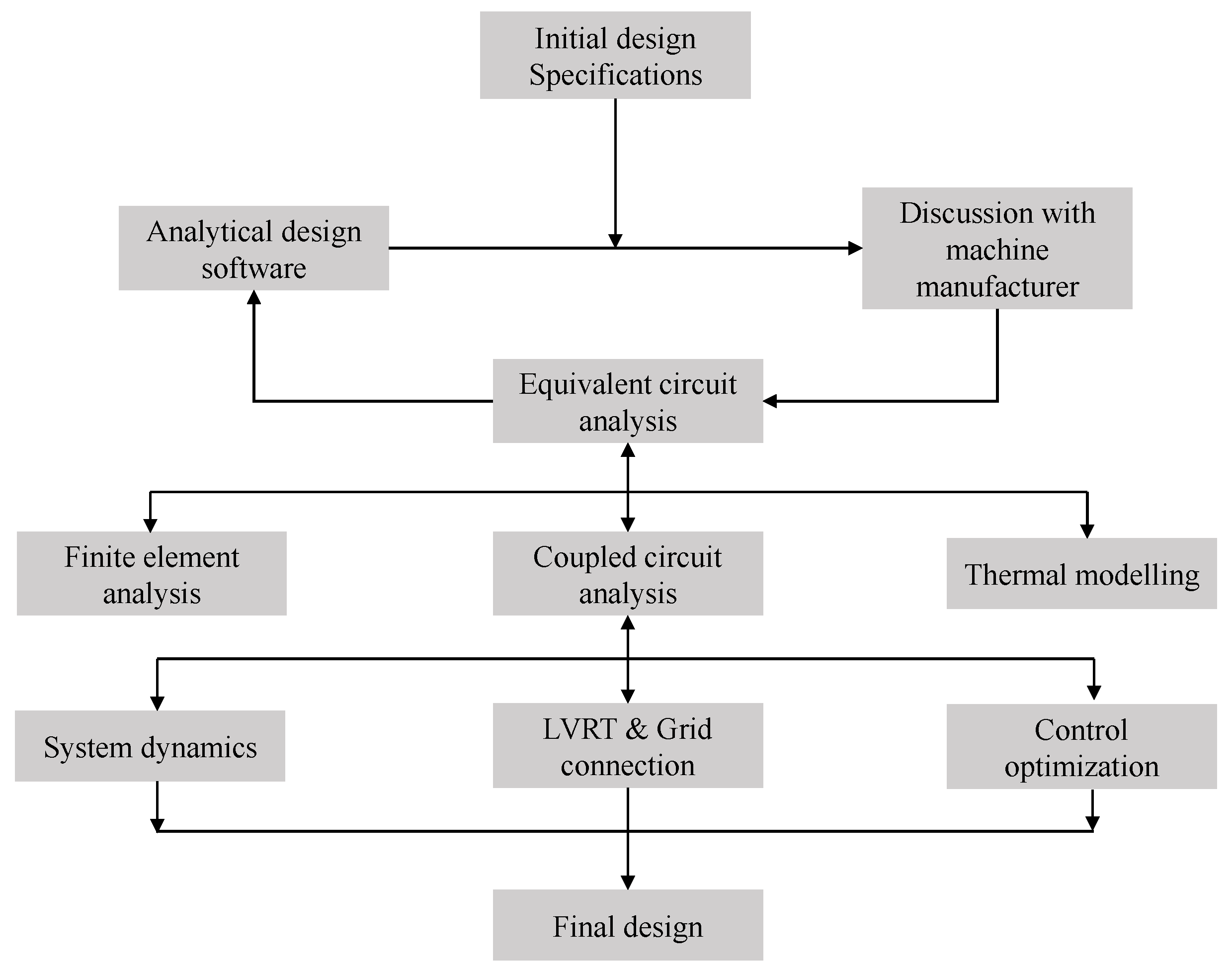
Figure 5. Proposed design procedure for a 6-MW BDFM [29].
Available BDFM electric equivalent circuit (EEC) models are limited in evaluating saturation, and FEA models are computationally costly. In light of these, a design approach for BDFMs using an EEC alongside a magnetic equivalent circuit (MEC) model is presented in [32]. The MEC developed in [33], is used to determine the flux distribution by the PW and CW, while the EEC model uses the MEC results to determine the machine performance.
It was noted in [34], that investigations on the design of BDFMs are limited in available literature. To that effect, a comprehensive BDFM design procedure considering the electromagnetic and thermal aspects of the BDFM, is presented in [34], with details of some of the models used given in [35]. A flowchart of the design procedure is given in Figure 6a. An EEC model is used to evaluate stator and rotor currents, while a static MEC as presented [35], is used to analyze the flux density distributions and core loss caused by these currents.
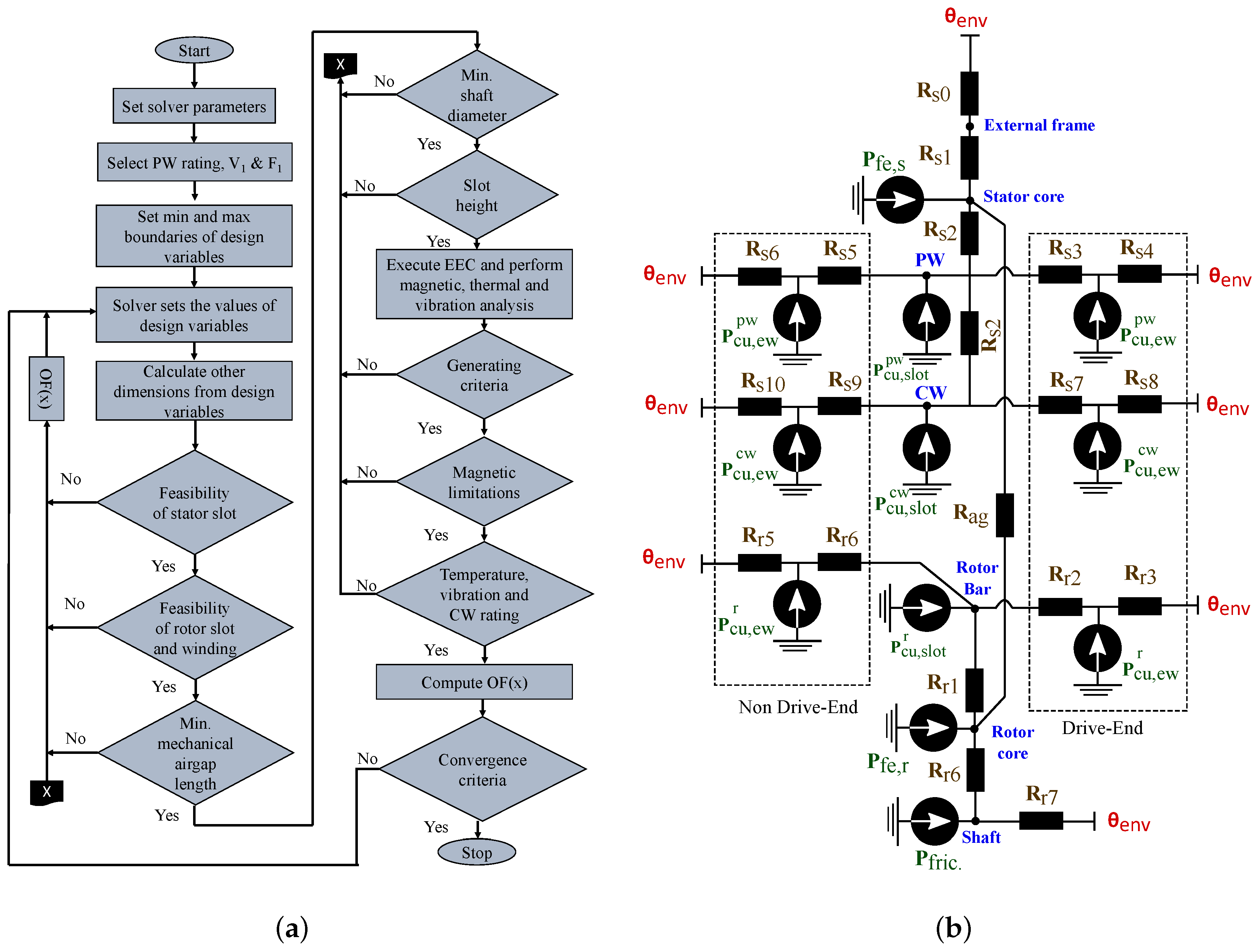
Figure 6. Design process and thermal model in [34]: (a) Design flow chart, and (b) Radial equivalent thermal network of a BDFM.
Temperature analysis is conducted in the design process in [34] using a lumped parameter thermal model illustrated in Figure 6b. The machine sections are designated as resistances, with the losses identified as heat sources.
An optimization process using the imperialist competitive algorithm is used to maximize the power to weight ratio, efficiency, power factor, while minimizing the voltage regulation and rotor differential leakage inductance in [34]. Feasibility of different aspects of the BDFM design are monitored, such as the stator and rotor slots, the airgap length, shaft diameter etc. However, it is the CW power factor that was being maximized. The CW is also seemingly placed closest to the airgap.
An iterative (Tabu search) method is used to optimize the stator of a 180 frame size BDFM based on its per phase equivalent circuit model in [36]. The optimization was used to demonstrate how appropriate division of the stator slot area between the PW and CW, can enable BDFM operation at the magnetic and electric loading limits. This maximizes the power output, as was demonstrated by the 21 % increase in power from the original design. This method of optimization is also applied to a D160 frame BDFM in [37], to optimize the electric and magnetic loadings. The maximum motoring torque with a lower limit on the PW power factor of 0.75 is used for machine evaluation in the optimization process.
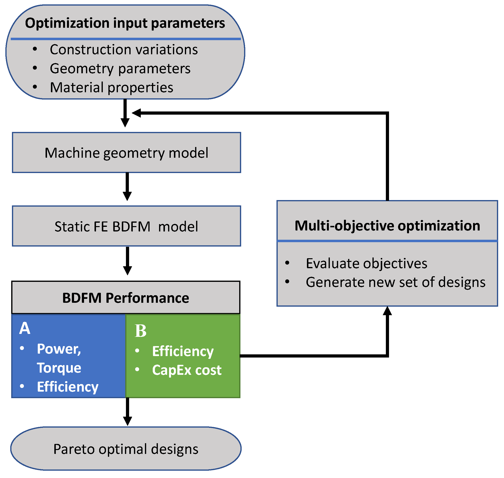
A magnetostatic FE BDFM model is presented in [38][39] to enable computationally efficient and accurate optimization processes. The non-dominated sorting genetic algorithm (NSGA-II) is used in [38] alongside the magnetostatic FE model to optimize the torque and efficiency of a BDFM designed for a D180 frame size. Geometric variables such as the stator inner radius and the ratios of slot/yoke height are used in the optimization process. The NSGA-II is also used in an optimization process in [40] to optimize the material cost and efficiency of a 3.2 MW BDFM. Similar geometric variables and magnetostatic FE models like in [38], are used in the optimization process in [40].
Both optimization processes in [38][40] are illustrated in Figure 7; A & B representing the optimized BDFM performances in [38][40] respectively. Different pole pair combinations are tested in the optimization process in [38], with the 2/3 combination having the superior performance. However the 4/6 pole pair combination is used for the 3.2 MW BDFM in [40], because of the effects of the presence of UMP using the 2/3 combination. It is worth noting that the machines in [38][40] are optimized at the maximum torque operation points.
In [41], researchers presented a BDFM design process. A modified version of that process is presented here. The design process of a BDFM is represented with two intertwined processes; the geometric and winding design process illustrated in Figure 8a, and the power density optimization process illustrated in Figure 8b. The geometric process is used for each design iteration in the optimization process. Given the absence of specific values for the stack aspect ratio, electric and magnetic loadings in literature, practical values are identified during an optimization process, and these values are used in the final geometric and winding design of the BDFM.
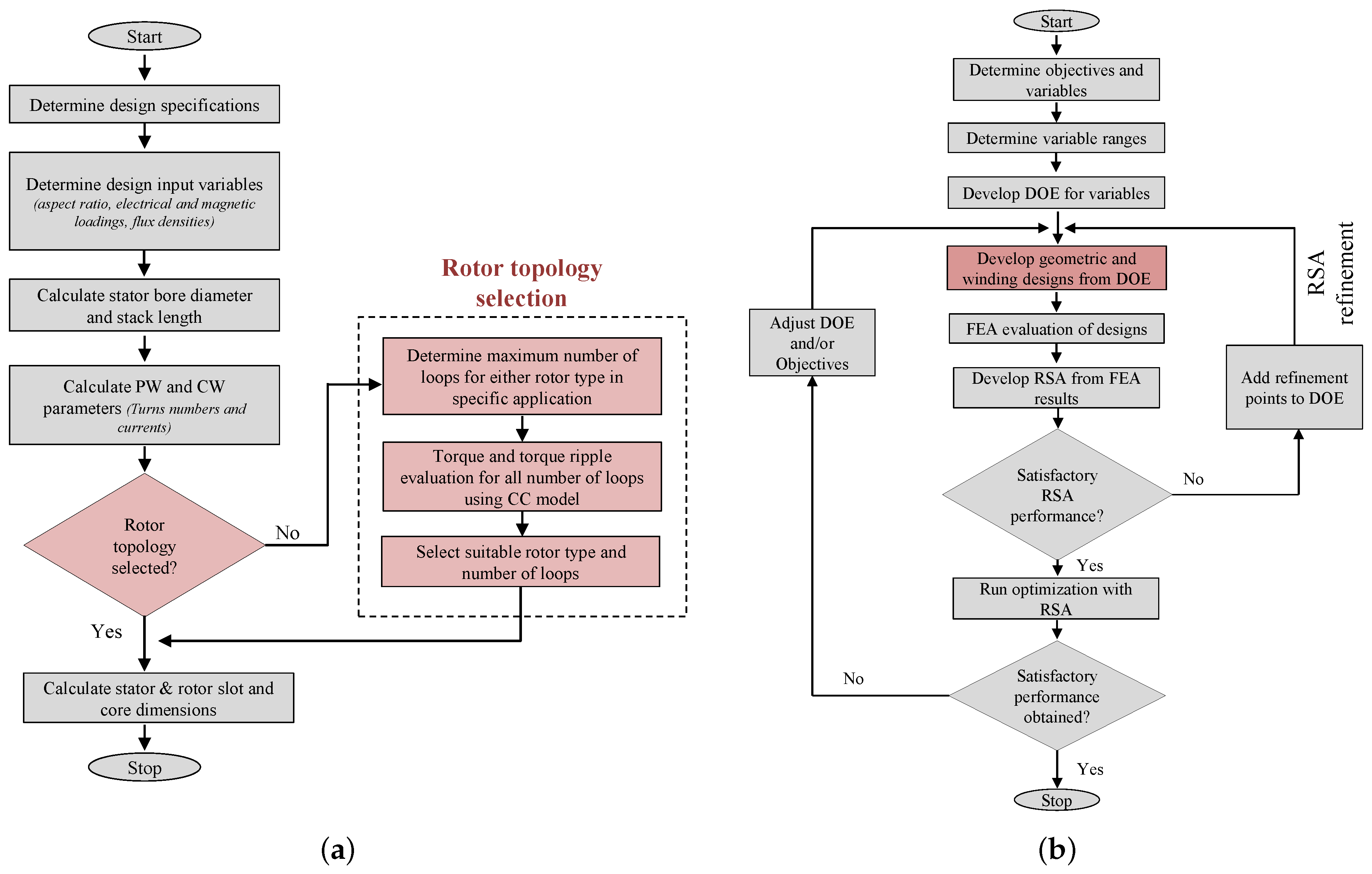
Figure 8. Design process: (a) Geometric and winding design process and (b) optimization process.
In this design process, the CC model developed in [15] is used to determine the appropriate rotor type and structure (number of loops) for individual design applications. The optimization process which also employs the NSGA-II is used to maximize the efficiency and power density at power output constraints. It is demonstrated in [42], how the power output of BDFMs varies with PW power factor, such that the maximum generated power from a design may be much larger than the power generated at PW unity power factor. As a result, power output at PW unity power factor is used in the optimization process in [41]. A response surface approximation (RSA) developed from 2-D transient FEA results is used with the NSGA-II. The RSA is used to enable computational efficiency in the optimization process.
This entry is adapted from the peer-reviewed paper 10.3390/en15030725
References
- Hunt, L.J. The “cascade” induction motor. J. Inst. Electr. Eng. 1914, 52, 406–426.
- Wallace, A.K.; Spee, R.; Lauw, H.K. Dynamic modeling of brushless doubly-fed machines. In Proceedings of the Conference Record of the IEEE Industry Applications Society Annual Meeting, San Diego, CA, USA, 1–5 October 1989; pp. 329–334.
- Rochelle, P.; Spee, R.; Wallace, A.K. The effect of stator winding configuration on the performance of brushless doubly-fed machines in adjustable speed drives. In Proceedings of the Conference Record of the 1990 IEEE Industry Applications Society Annual Meeting, Seattle, WA, USA, 7–12 October 1990; pp. 331–337.
- Hunt, L.J. A new type of induction motor. Electr. Eng. J. Inst. 1907, 39, 648–667.
- Oraee, A.; Abdi, E.; McMahon, R.A. Converter rating optimisation for a brushless doubly fed induction generator. IET Renew. Power Gener. 2015, 9, 360–367.
- Broadway, A.R.W.; Burbridge, L. Self-cascaded machine: A low-speed motor or high-frequency brushless alternator. Electr. Eng. Proc. Inst. 1970, 117, 1277–1290.
- Strous, T.D.; Polinder, H.; Ferreira, J.A. Brushless doubly-fed induction machines for wind turbines: Developments and research challenges. IET Electr. Power Appl. 2017, 11, 991–1000.
- Roberts, P.C. A Study of Brushless Doubly-Fed (Induction) Machines. Ph.D. Thesis, University of Cambridge, Cambridge, UK, 2004.
- Mcmahon, R.; Tavner, P.; Abdi, E.; Malliband, P.; Barker, D. Characterising brushless doubly fed machine rotors. IET Electr. Power Appl. 2013, 7, 535–543.
- Xiong, F.; Wang, X. Design of a Low-Harmonic-Content Wound Rotor for the Brushless Doubly Fed Generator. IEEE Trans. Energy Convers. 2014, 29, 158–168.
- Logan, T.G.; McMahon, R.A.; Tavner, P.J.; Tohidi, S. A comparison of cage and nested-loop BDFM rotors. In Proceedings of the 6th IET International Conference on Power Electronics, Machines and Drives (PEMD 2012), Bristol, UK, 27–29 March 2012; pp. 1–6.
- Abdi, S.; Grace, A.; Abdi, E.; McMahon, R. A new optimized rotor design for brushless doubly fed machines. In Proceedings of the 20th International Conference on Electrical Machines and Systems (ICEMS), Sydney, NSW, Australia, 11–14 August 2017; pp. 1–6.
- Wallace, A.; Rochelle, P.; Spee, R. Rotor modeling and development for brushless doubly-fed machines. Electr. Mach. Power Syst. 1995, 23, 703–715.
- Wang, X.; Liu, D.; Polinder, H.; Lahaye, D.; Ferreira, J.A. Comparison of nested-loop rotors in brushless doubly-fed induction machines. In Proceedings of the 19th International Conference on Electrical Machines and Systems (ICEMS), Chiba, Japan, 13–16 November 2016; pp. 1–6.
- Olubamiwa, O.I.; Gule, N.; Kamper, M.J. Coupled circuit analysis of the brushless doubly fed machine using the winding function theory. IET Electr. Power Appl. 2020, 14, 1558–1569.
- McMahon, R.A.; Mathekga, M.E.; Wang, X.; Tatlow, M.R. Design considerations for the brushless doubly-fed (induction) machine. IET Electr. Power Appl. 2016, 10, 394–402.
- McMahon, R.A.; Roberts, P.C.; Wang, X.; Tavner, P.J. Performance of BDFM as generator and motor. IEE Proc. Electr. Power Appl. 2006, 153, 289–299.
- Oraee, A.; McMahon, R.; Abdi, E.; Abdi, S.; Ademi, S. Influence of Pole-pair Combinations on the Characteristics of the Brushless Doubly Fed Induction Generator. IEEE Trans. Energy Convers. 2020, 35, 1151–1159.
- Strous, T.D.; Shipurkar, U.; Polinder, H.; Ferreira, J.A. Comparing the Brushless DFIM to other Generator Systems for Wind Turbine Drive-Trains. J. Phys. Conf. Ser. 2016, 753, 112014.
- Abdi, S.; Abdi, E.; Oraee, A.; McMahon, R. Optimization of Magnetic Circuit for Brushless Doubly Fed Machines. IEEE Trans. Energy Convers. 2015, 30, 1611–1620.
- Abdi, E.; Oraee, A.; Abdi, S.; McMahon, R.A. Design of the Brushless DFIG for optimal inverter rating. In Proceedings of the 7th IET International Conference on Power Electronics, Machines and Drives (PEMD 2014), Manchester, UK, 8–10 April 2014; pp. 1–6.
- Abdi, S.; Abdi, E.; Oraee, A.; McMahon, R.A. Investigation of magnetic wedge effects in large-scale BDFMs. In Proceedings of the 2nd IET Renewable Power Generation Conference (RPG 2013), Beijing, China, 9–11 September 2013; pp. 1–4.
- Logan, T.; Mcmahon, R.; Seffen, K. Noise and vibration in brushless doubly fed machine and brushless doubly fed reluctance machine. IET Electr. Power Appl. 2014, 8, 50–59.
- Strous, T.D.; Wang, X.; Polinder, H.; Ferreira, J.A.B. Brushless doubly-fed induction machines: Torque ripple. In Proceedings of the 2015 IEEE International Electric Machines Drives Conference (IEMDC), Coeur d’Alene, ID, USA, 10–13 May 2015; pp. 1145–1151.
- Strous, T.D.; Wang, X.; Polinder, H.; Ferreira, J.A. Evaluating Harmonic Distortions in Brushless Doubly Fed Induction Machines. IEEE Trans. Magn. 2017, 53, 1–10.
- Chen, J.; Zhang, W. Harmonics in Brushless Doubly Fed Induction Generator for Torque Ripple Analysis and Modeling. IEEE Trans. Magn. 2014, 50, 1–4.
- Gorginpour, H.; Jandaghi, B.; Oraee, A.; Saket, M.A.; Ahmadian, M.; Oraee, H. Reduction of the torque ripple in Brushless Doubly-Fed Machine. In Proceedings of the 2011 3rd International Youth Conference on Energetics (IYCE), Leiria, Portugal, 7–9 July 2011; pp. 1–7.
- Wang, X.; Strous, T.D.; Lahaye, D.; Polinder, H.; Ferreira, J.A. Effects of rotor skew on the performance of brushless doubly-fed induction machine. In Proceedings of the 2015 IEEE International Electric Machines Drives Conference (IEMDC), Coeur d’Alene, ID, USA, 10–13 May 2015; pp. 260–265.
- Abdi, E.; Tatlow, M.R.; McMahon, R.A.; Tavner, P. Design and performance analysis of a 6 MW medium-speed Brushless DFIG. In Proceedings of the 2nd IET Renewable Power Generation Conference (RPG 2013), Beijing, China, 9–11 September 2013; pp. 1–4.
- Roberts, P.C.; McMahon, R.A.; Tavner, P.J.; Maciejowski, J.M.; Flack, T.J. Equivalent circuit for the brushless doubly fed machine (BDFM) including parameter estimation and experimental verification. IEE Proc. Electr. Power Appl. 2005, 152, 933–942.
- Abdi, E.; Mcmahon, R.; Malliband, P.; Shao, S.; Mathekga, M.E.; Tavner, P.; Abdi, S.; Oraee, A.; Long, T.; Tatlow, M. Performance analysis and testing of a 250 kW medium-speed brushless doubly-fed induction generator. IET Renew. Power Gener. 2013, 7, 631–638.
- Chang, Y.H.; Li, Y.T.; Lin, I.H.; Hsieh, M.F. A design approach integrating the magnetic circuit and electric circuit models for BDFIM. In Proceedings of the 2014 17th International Conference on Electrical Machines and Systems (ICEMS), Hangzhou, China, 22–25 October 2014; pp. 1685–1690.
- Hsieh, M.F.; Lin, I.H.; Hsu, Y.C.; McMahon, R.A. Design of Brushless Doubly-Fed Machines Based on Magnetic Circuit Modeling. IEEE Trans. Magn. 2012, 48, 3017–3020.
- Gorginpour, H.; Oraee, H.; McMahon, R.A. Electromagnetic-Thermal Design Optimization of the Brushless Doubly Fed Induction Generator. IEEE Trans. Ind. Electron. 2014, 61, 1710–1721.
- Gorginpour, H.; Oraee, H.; McMahon, R.A. A Novel Modeling Approach for Design Studies of Brushless Doubly Fed Induction Generator Based on Magnetic Equivalent Circuit. IEEE Trans. Energy Convers. 2013, 28, 902–912.
- Wang, X.; Roberts, P.C.; McMahon, R.A. Optimisation of BDFM stator design using an equivalent circuit model and a search method. In Proceedings of the 3rd IET International Conference on Power Electronics, Machines and Drives (PEMD 2006), Dublin, Ireland, 4–6 April 2006; pp. 606–610.
- Wang, X.; McMahon, R.A.; Tavner, P.J. Design of the Brushless Doubly-Fed (Induction) Machine. In Proceedings of the 2007 IEEE International Electric Machines Drives Conference, Antalya, Turkey, 3–5 May 2007; pp. 1508–1513.
- Wang, X.; Strous, T.D.; Lahaye, D.; Polinder, H.; Ferreira, J.A. Modeling and Optimization of Brushless Doubly-Fed Induction Machines Using Computationally Efficient Finite-Element Analysis. IEEE Trans. Ind. Appl. 2016, 52, 4525–4534.
- Wang, X.; Strous, T.D.; Lahaye, D.; Polinder, H.; Ferreira, J.A. Finite element modeling of brushless doubly-fed induction machine based on magneto-static simulation. In Proceedings of the 2015 IEEE International Electric Machines Drives Conference (IEMDC), Coeur d’Alene, ID, USA, 10–13 May 2015; pp. 315–321.
- Wang, X.; Polinder, H.; Lahaye, D.; Ferreira, J.A. FE based multi-objective optimization of a 3.2 MW brushless doubly-fed induction machine. In Proceedings of the 2017 IEEE Workshop on Electrical Machines Design, Control and Diagnosis (WEMDCD), Nottingham, UK, 20–21 April 2017; pp. 89–94.
- Olubamiwa, O.I.; Gule, N. Design and optimization of a Cage + Nested loops rotor BDFM. In Proceedings of the 2020 International Conference on Electrical Machines (ICEM), Gothenburg, Sweden, 23–26 August 2020; pp. 1868–1874.
- Olubamiwa, O.I.; Gule, N. Prioritizing power factor in power density assessments of doubly fed induction generator alternatives. In Proceedings of the 2020 International Symposium on Power Electronics, Electrical Drives, Automation and Motion (SPEEDAM), Sorrento, Italy, 24–26 June 2020; pp. 47–52.
This entry is offline, you can click here to edit this entry!