Your browser does not fully support modern features. Please upgrade for a smoother experience.
Please note this is an old version of this entry, which may differ significantly from the current revision.
Green hydrogen production is at the core of the transition away from conventional fuels. Along with popularly investigated pathways for hydrogen production, thermochemical water splitting using redox materials is an interesting option for utilizing thermal energy, as this approach makes use of temperature looping over the material to produce hydrogen from water. Solar reactors have conventionally been used for such reactions, as temperatures up to 2000 °C can be reached, which are beneficial for the reduction of the redox material.
- hydrogen
- two-step thermochemical water splitting
- redox cycles
1. Introduction
Over the past few years, there has been great interest in sustainable carbon-free fuels. A large portion of the fuels used nowadays are fossil fuels, which have high energy density levels and with which carbon dioxide is emitted upon utilization. The consequences of such emissions are now becoming increasingly visible by means of increased carbon dioxide concentrations in the atmosphere, which are highly comparable to those 3–4 million years ago. During those times, the earth’s average temperature was ca. 3 °C higher and the sea levels were ca. 25 m higher than now. The dire consequences of such drastic environmental changes are well documented [1]. Therefore, a more sustainable energy alternative is needed in order to reduce carbon dioxide emissions and limit the impacts of fuels on the environment. Owing to the finite nature of fossil fuels, there has been growing interest in renewable carbon-free fuels, such as hydrogen. Hydrogen can be produced using water [2][3] and energy-dense [4][5]. Hydrogen can either be used in fuel cells or in internal combustion engines [6][7][8]. In fuel cells, hydrogen is split into H+ and electrons at the anode. These electrons flow through an external circuit to generate a current and then flow to the cathode, where they form water with H+ and oxygen [9][10]. In internal combustion engines, hydrogen is combusted with oxygen, which generates water and heat [6][7][8]. In both cases, only water is formed and no carbon dioxide or any other environmental pollutants are generated.
Although hydrogen is often proposed as a sustainable alternative, this largely depends on the method with which the hydrogen is produced [11]. How sustainable hydrogen is, depending on the energy source, is indicated by three main colors: grey, blue or green [12]. The most polluting variant is grey hydrogen, because fossil fuels are utilized in the production of hydrogen. Blue hydrogen is also produced using fossil fuels, but the difference compared to grey hydrogen is that the produced carbon dioxide is captured and stored, such that the impact on the environment is reduced. The most sustainable type of hydrogen is green hydrogen. In order to receive this grading, the hydrogen should be produced from 100% renewable energy [12][13]. There are several different pathways through which hydrogen can be generated. Steam reformation of fossil fuels is currently the major pathway for hydrogen production. In the process of steam reforming, the fossil fuels react with water to produce hydrogen, carbon monoxide and some carbon dioxide. In order to enrich the hydrogen phase, the water–gas shift reaction is often performed after reformation. In this reaction, carbon monoxide and water are in equilibrium with hydrogen and carbon dioxide [14]. Although producing hydrogen in this way is relatively cheap [4][14][15], greenhouse gases are emitted and fossil fuels are utilized, such that this hydrogen is classified as grey hydrogen, meaning this method can no longer be regarded as sustainable. Biomass gasification is another method proposed for hydrogen production. In this process, the biomass reacts with steam or air to generate hydrogen. Theoretically, this synthesis method has a very large feedstock [16], but many impurities can be present in the feedstock [15], which induces operational difficulties. Next to hydrogen and carbon monoxide, methane and carbon dioxide are formed [17], both of which are greenhouse gases that contribute to global warming. Although renewable hydrogen is produced, the fuel is not carbon-free, since carbon-containing gases are indirectly emitted.
Alternatively, hydrogen can also be produced through currently popular approaches, such as electrolysis and photo-assisted water splitting methods, provided that green electricity is used [16]. The past decades have seen extensive efforts regarding hydrogen production via water splitting reaction by employing different strategies, such as photo-, electro-, photo-electro- or thermo-based methods. Electrolysis, photolysis and combined photoelectrochemical water splitting for the production of hydrogen are a few of the actively investigated research topics in the field of renewable energy research. For electrolysis-based systems, polymer electrolyte membrane electrolyzers have attracted much attention due to their compactness, quick response times and improved current densities [18]. The photolysis method has been considered as a thorough solution as it utilizes solar energy, either directly or in the form of electricity, to produce hydrogen [19]. Despite the progress in renewable hydrogen production methods, the majority (95%) of hydrogen is still coming from non-renewable sources, and water splitting only accounts for 3.9% of the total hydrogen production [20]. In order to fulfil the future needs for green hydrogen production, it is imperative to explore all possible pathways to harness hydrogen from water by using renewable energy sources [15][21][22].
2. Solar Reactors in Hydrogen Production through Thermochemical Water Splitting
Solar reactors have conventionally been used for such reactions, as temperatures up to 2000 °C can be reached, which are beneficial for the reduction of the redox material. In order to collect the solar energy, the solar light must first be concentrated. The concentrated light is then reflected onto a receiver where the temperature is reached [23][24]. Concentration of the solar light is achieved through a heliostat field or a parabolic dish system. These two technologies are well-developed and their schematics are shown in Figure 1 [23]. Although these high temperatures are required to reach high hydrogen production rates, a major drawback is that the solar radiation can damage the samples, for example through degradation [25].
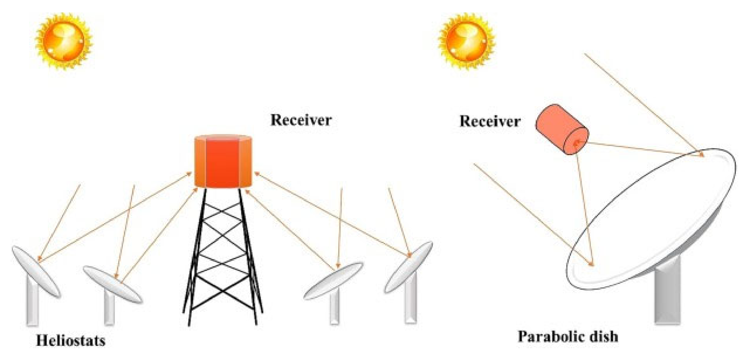 Figure 1. Schematic representation of a heliostat field (left) and a parabolic dish system (right), which are two well-developed technologies used to concentrate sunlight [23].
Figure 2 describes the solar setup proposed by Chueh et al. to carry out the thermochemical water splitting cycles over ceria [26]. The concentrated sunlight passes through a quartz window and is concentrated onto the sample. The reduction reaction was performed at a temperature of approximately 1600 °C for 1 h in argon, whereas at 500 °C the hydrogen was generated by passing a gaseous mixture of argon and water for about 30 min over the reduced redox material. In the same research, the performance of the solar reactor for thermochemical cycling of ceria for hydrogen generation was compared to the performance using an infrared furnace. The conditions slightly differed as higher flow rates could be attained in the furnace. Furthermore, the reduction reaction was performed at 1500 °C for 20 min and the oxidation reaction was performed at 800 °C for 10 min. It was found that higher generation rates for oxygen and hydrogen could be reached using an infrared furnace compared to the solar reactor. An additional advantage of the furnace over the solar reactor was that a stable temperature could be maintained [26]. Reactors using an infrared furnace are discussed in more detail in the next section.
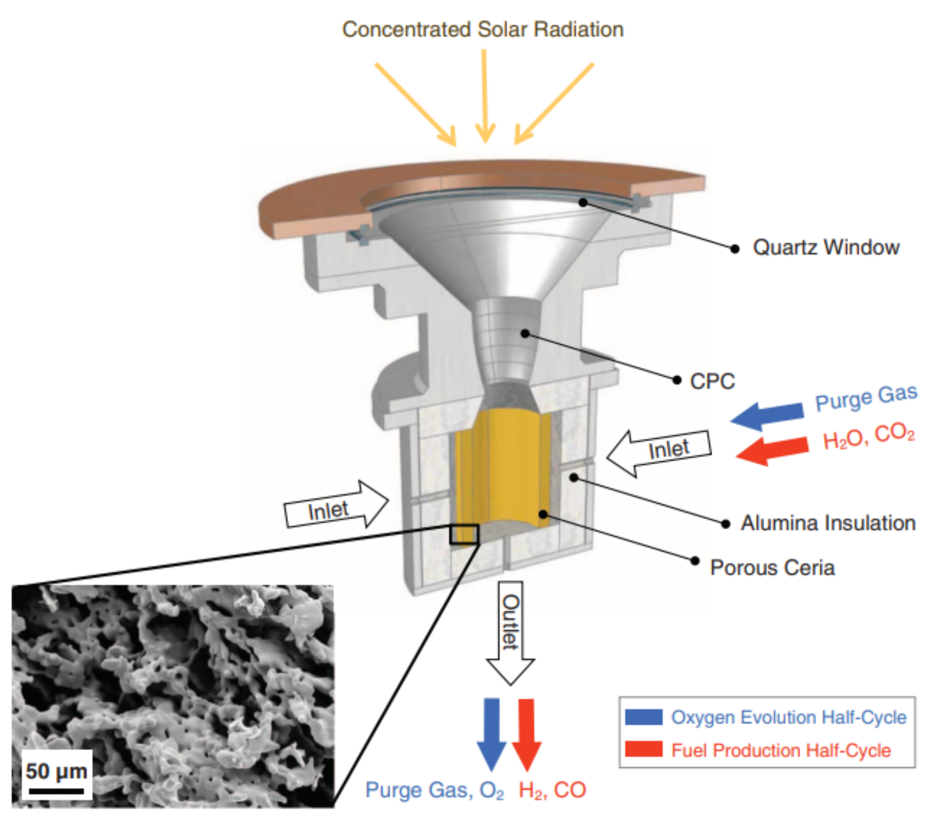 Figure 2. Schematic representation of the solar reactor used for thermochemical water splitting. The redox material used in porous ceria. As the same setup was used in another experiment for syngas production, carbon dioxide and carbon monoxide are also denoted in the figure, as well as a scanning electron microscope image of ceria after 23 cycles. Reprinted from [26].
In a setup similar to the one shown in Figure 2, Fe3O4 was reduced to FeO in a report by Charvin et al. The sample was placed in the solar reactor and cooled by water. During the reduction reaction, nitrogen was supplied to the reactor. Only the reduction reaction was performed in the solar reactor, while the oxidation reaction was carried out in an electrical furnace to reach temperatures below 800 °C, which are preferred for this reaction type according to its thermodynamics. Steam carried by argon was supplied to the furnace containing the sample. A schematic representation of the setup used for water splitting is shown in Figure 3 [27].
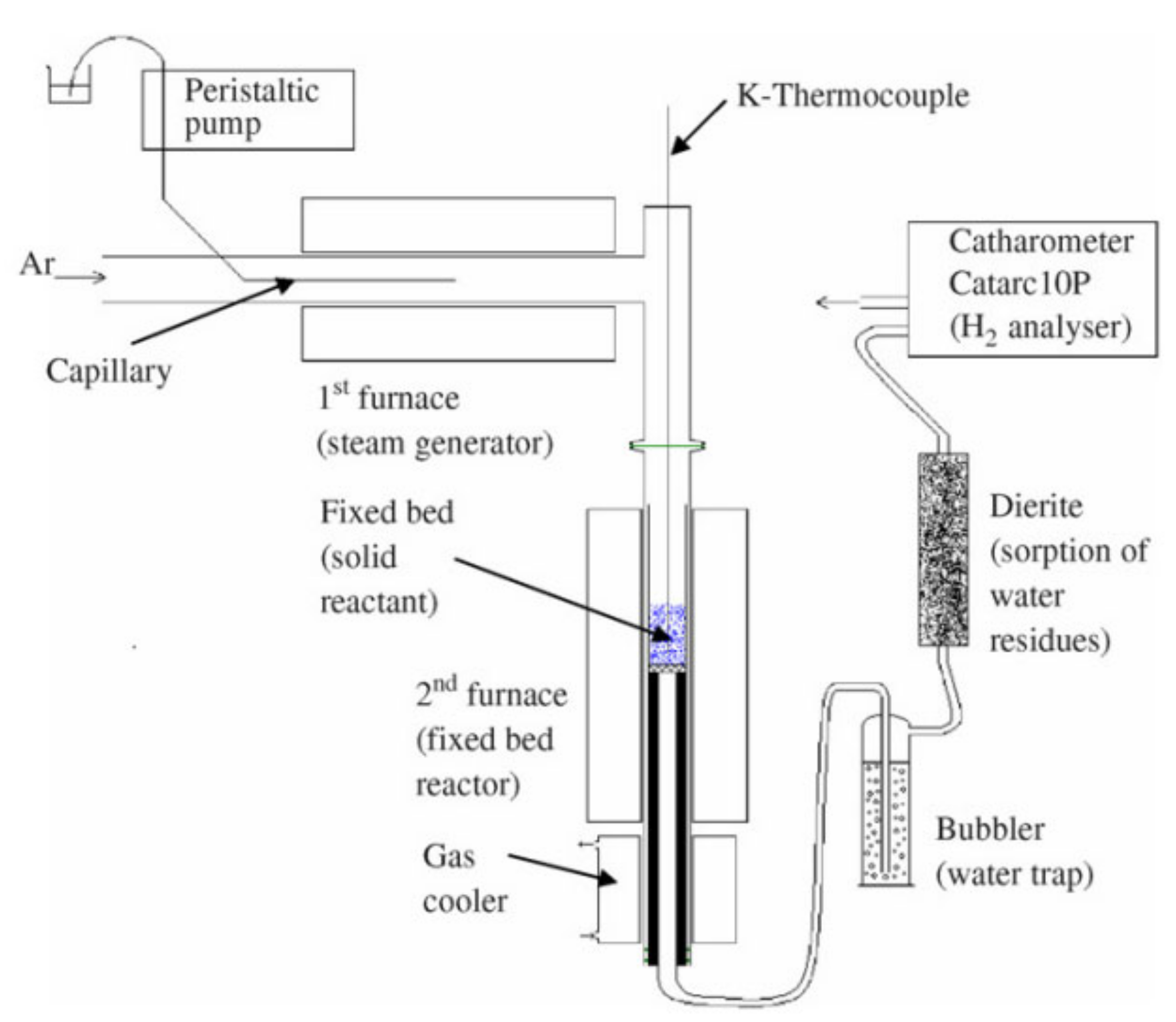 Figure 3. Schematic representation of the experimental setup used for the oxidation of FeO to Fe3O4 for hydrogen production. Reprinted from [27].
Oliveira et al. reported on a solar reactor used for thermochemical cycling of cork-templated ceria. The samples were placed in an alumina tube and then placed in the solar reactor. In contrast to the setup shown in Figure 2, the concentrated solar light entered the reactor from the side instead of from the top. The reduction temperature was 1400 °C and the reaction took place while argon was passed over the sample. At the end of the reduction process, the material was marked by low and constant oxygen generation for 15 min. The temperature was then lowered by not supplying any solar radiation to the reactor and without additional cooling. When the oxygen concentration was approximately zero, a gaseous mixture of argon and water was supplied to the reactor and the oxidation reaction took place. A schematic representation of the reactor is shown in Figure 4 [24].
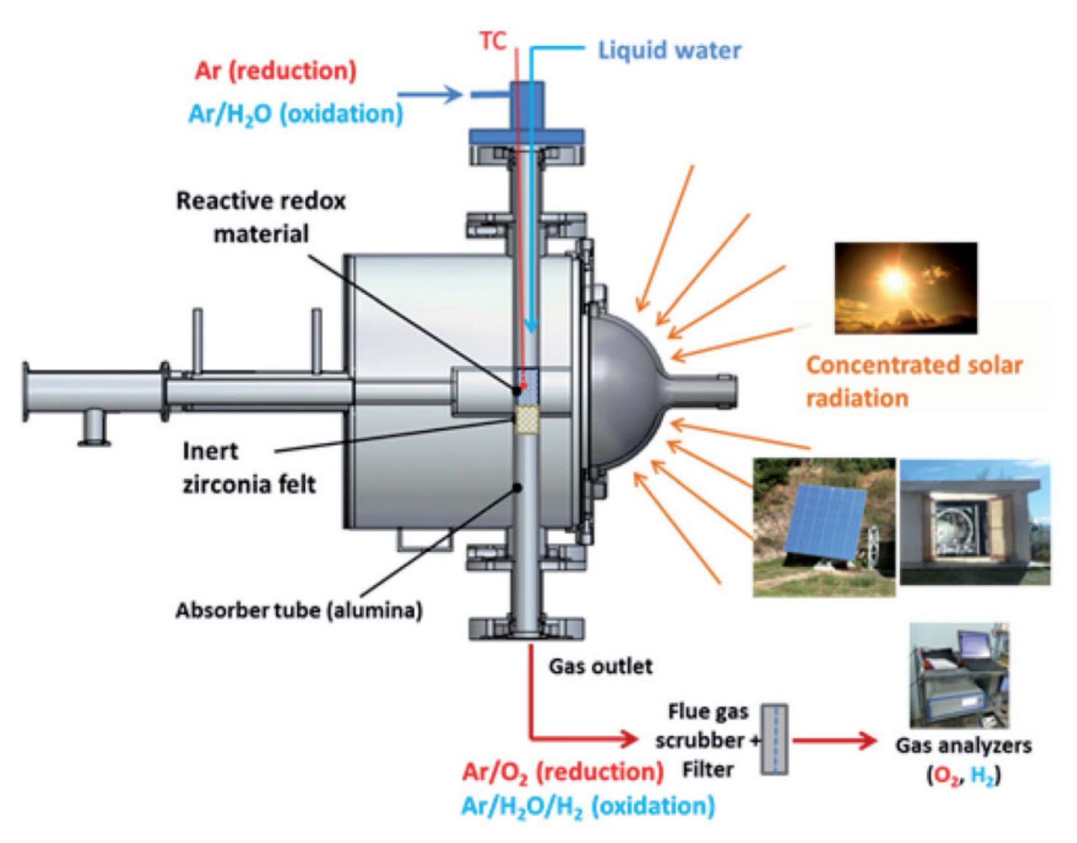 Figure 4. Schematic representation of a solar reactor used for thermochemical redox cycling of cork-templated ceria. The reduction temperature was 1400 °C and the oxidation reaction took place during free cooling when the oxygen concentration dropped to approximately zero. Reprinted from [24].
A solar reactor was reviewed by Al-Shankiti et al. for isothermal and thermochemical water splitting [28]. The reactor is a packed bed reactor, where the bedding is indirectly radiated by solar light. Either steam or an inert gas can be supplied to the bed through different openings. The main disadvantage of this reactor is the non-uniformity of the temperature profile inside the reactor, which can be mitigated by fluidizing the particles. The reactor’s schematic representation is shown in Figure 5 where numbers from 1 to 6 are the fixed bed reactor tubes.
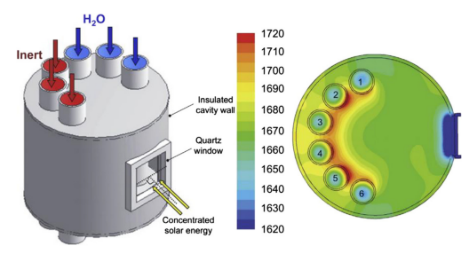 Figure 5. Isothermal reactor used for thermochemical water splitting. Reprinted from [29].
Figure 6 shows a schematical representation of a solar reactor with fluidized particles, as used by Kodama et al. The solar radiation passing through the quartz window directly heats the particles, such that the bed can reach temperatures of up to 1400 °C. Due to the fluidization of the bed, the heated particles move down, while the unheated particles move up towards the quartz window. As the particles move counter-currently, heat can be exchanged. In order to conduct reduction and oxidation reactions for hydrogen production using two-step thermochemical water splitting, the gas flow is either nitrogen or steam for the reduction and oxidation reaction, respectively. The temperature of the bed is changed from 1400 °C to 1000 °C upon steam injection [30]. This reactor design was used as inspiration for an experimental setup proposed by Gokon et al. for the thermal reduction of NiFe2O4 supported on monoclinic zirconia. The subsequent water splitting step was carried out in the setup shown in Figure 7b [31].
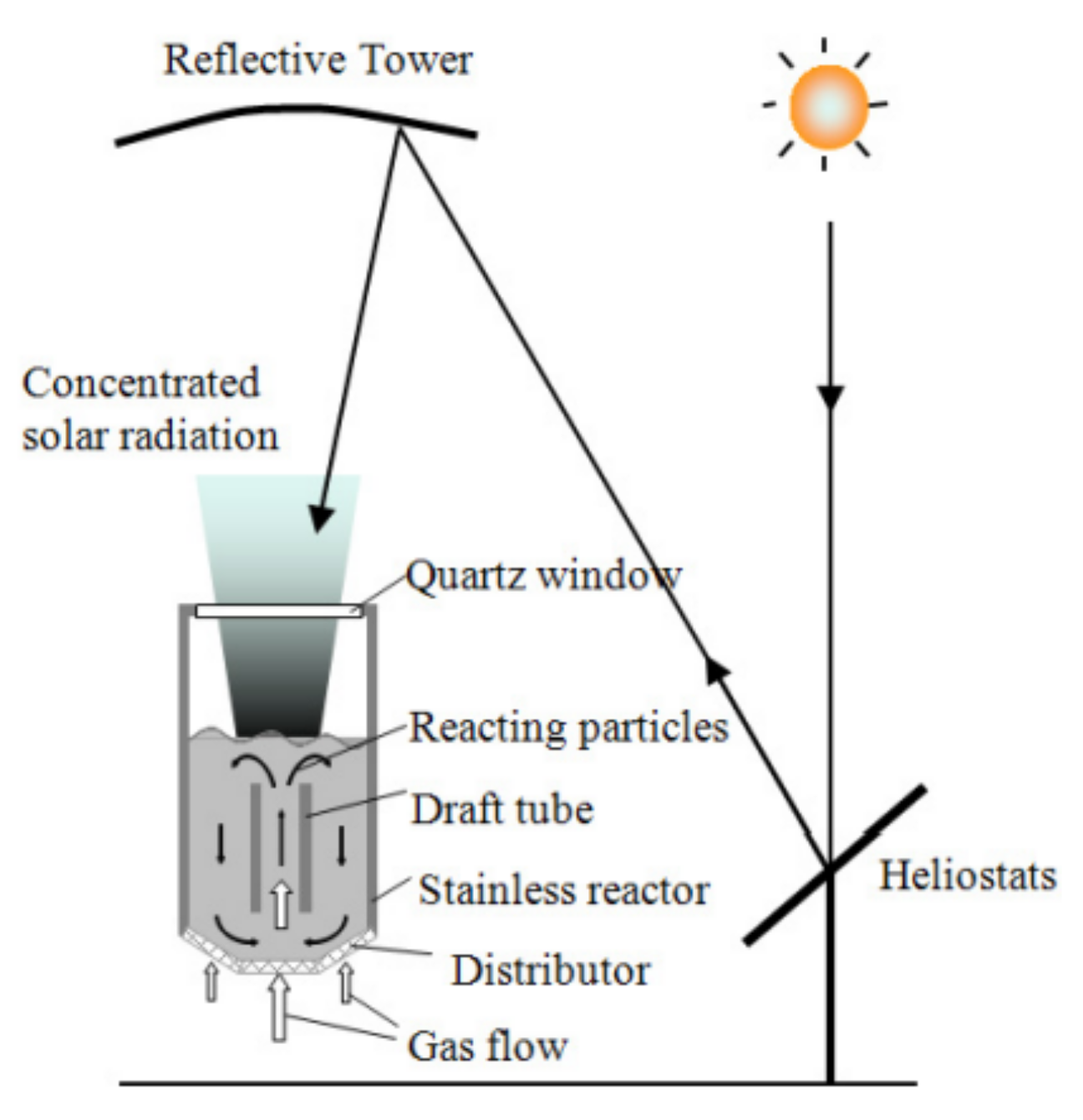 Figure 6. Fluidized-bed solar reactor for two-step thermochemical water splitting. The reduction reaction takes place in a nitrogen atmosphere at 1400 °C and steam is supplied for the oxidation reaction, which is conducted at 1000 °C. Reprinted from [30].
 Figure 7. Schematic representation of the experimental setup used for (a) thermochemical reduction of Fe3O4 supported on yttria-stabilized zirconia and NixFe3−xO4 supported on monoclinic zirconia, as well as (b) oxidation of NixFe3−xO4 supported on monoclinic zirconia. The reduction temperature was 1400 °C and the oxidation temperature was 1000 °C for both redox materials. Reprinted from [32].
This entry is adapted from the peer-reviewed paper 10.3390/en15093044
References
- Goelzer, H.; Nowicki, S.; Payne, A.; Larour, E.; Seroussi, H.; Lipscomb, W.H.; Gregory, J.; Abe-Ouchi, A.; Shepherd, A.; Simon, E.; et al. The future sea-level contribution of the Greenland ice sheet: A multi-model ensemble study of ISMIP6. Cryosphere 2020, 14, 3071–3096.
- Seo, K.; Lim, T.; Mills, E.M.; Kim, S.; Ju, S. Hydrogen generation enhanced by nano-forest structures. RSC Adv. 2016, 6, 12953–12958.
- Roychowdhury, S.; Mukthar Ali, M.; Dhua, S.; Sundararajan, T.; Ranga Rao, G. Thermochemical hydrogen production using Rh/CeO2/γ-Al2O3 catalyst by steam reforming of ethanol and water splitting in a packed bed reactor. Int. J. Hydrogen Energy 2021, 46, 19254–19269.
- Safari, F.; Dincer, I. A review and comparative evaluation of thermochemical water splitting cycles for hydrogen production. Energy Convers. Manag. 2020, 205, 112182.
- Dundar-Tekkaya, E.; Yürüm, Y. Mesoporous MCM-41 material for hydrogen storage: A short review. Int. J. Hydrogen Energy 2016, 41, 9789–9795.
- Luo, Q.-H.; Hu, J.-B.; Sun, B.-G.; Liu, F.-S.; Wang, X.; Li, C.; Bao, L.-Z. Experimental investigation of combustion characteristics and NOx emission of a turbocharged hydrogen internal combustion engine. Int. J. Hydrogen Energy 2019, 44, 5573–5584.
- Ciniviz, M.; Köse, H. Hydrogen Use in Internal Combustion Engine: A Review. Int. J. Automot. Eng. Technol. 2012, 1, 1–15.
- White, C.M.; Steeper, R.R.; Lutz, A.E. The hydrogen-fueled internal combustion engine: A technical review. Int. J. Hydrogen Energy 2006, 31, 1292–1305.
- Kulkarni, T.; Slaughter, G. Enzymatic Glucose Biofuel Cell and its Application. J. Biochips Tissue Chips 2015, 5, 1000111.
- Tuan, K.N.; Karpukhin, K.E.; Terenchenko, A.S.; Kolbasov, A.F. World trends in the development of vehicles with alternative energy sources. ARPN J. Eng. Appl. Sci. 2018, 13, 2535–2542.
- Acar, C.; Dincer, I. 3.1 Hydrogen Production. In Comprehensive Energy Systems; Dincer, I., Ed.; Elsevier: Oxford, UK, 2018; pp. 1–40.
- Dawood, F.; Anda, M.; Shafiullah, G.M. Hydrogen production for energy: An overview. Int. J. Hydrogen Energy 2020, 45, 3847–3869.
- Kakoulaki, G.; Kougias, I.; Taylor, N.; Dolci, F.; Moya, J.; Jäger-Waldau, A. Green hydrogen in Europe—A regional assessment: Substituting existing production with electrolysis powered by renewables. Energy Convers. Manag. 2021, 228, 113649.
- LeValley, T.L.; Richard, A.R.; Fan, M. The progress in water gas shift and steam reforming hydrogen production technologies—A review. Int. J. Hydrogen Energy 2014, 39, 16983–17000.
- Acar, C.; Dincer, I. Comparative assessment of hydrogen production methods from renewable and non-renewable sources. Int. J. Hydrogen Energy 2014, 39, 1–12.
- Acar, C.; Dincer, I. Review and evaluation of hydrogen production options for better environment. J. Clean. Prod. 2019, 218, 835–849.
- Detchusananard, T.; Im-orb, K.; Ponpesh, P.; Arpornwichanop, A. Biomass gasification integrated with CO2 capture processes for high-purity hydrogen production: Process performance and energy analysis. Energy Convers. Manag. 2018, 171, 1560–1572.
- Shiva Kumar, S.; Himabindu, V. Hydrogen production by PEM water electrolysis—A review. Mater. Sci. Energy Technol. 2019, 2, 442–454.
- Zhang, K.; Ma, M.; Li, P.; Wang, D.H.; Park, J.H. Water Splitting Progress in Tandem Devices: Moving Photolysis beyond Electrolysis. Adv. Energy Mater. 2016, 6, 1600602.
- Singh, R.; Dutta, S. A review on H2 production through photocatalytic reactions using TiO2/TiO2-assisted catalysts. Fuel 2018, 220, 607–620.
- Ayers, K.; Anderson, E.; Capuano, C.; Carter, B.; Dalton, L.; Hanlon, G.; Manco, J.; Niedzwiecki, M. Research Advances Towards Low Cost, High Efficiency PEM Electrolysis. ECS Trans. 2010, 33, 3.
- Lee, J.E.; Shafiq, I.; Hussain, M.; Lam, S.S.; Rhee, G.H.; Park, Y.-K. A review on integrated thermochemical hydrogen production from water. Int. J. Hydrogen Energy 2022, 47, 4346–4356.
- Mao, Y.; Gao, Y.; Dong, W.; Wu, H.; Song, Z.; Zhao, X.; Sun, J.; Wang, W. Hydrogen production via a two-step water splitting thermochemical cycle based on metal oxide—A review. Appl. Energy 2020, 267, 114860.
- Costa Oliveira, F.A.; Barreiros, M.A.; Haeussler, A.; Caetano, A.P.F.; Mouquinho, A.I.; Oliveira e Silva, P.M.; Novais, R.M.; Pullar, R.C.; Abanades, S. High performance cork-templated ceria for solar thermochemical hydrogen production via two-step water-splitting cycles. Sustain. Energy Fuels 2020, 4, 3077–3089.
- Arribas, L.; Gonzalez-Aguilar, J.; Romero, M. Solar-Driven Thermochemical Water-Splitting by Cerium Oxide: Determination of Operational Conditions in a Directly Irradiated Fixed Bed Reactor. Energies 2018, 11, 2451.
- Chueh, W.; Falter, C.; Abbott, M.; Scipio, D.; Furler, P.; Haile, S.; Steinfeld, A. High-Flux Solar-Driven Thermochemical Dissociation of CO2 and H2O Using Nonstoichiometric Ceria. Science 2010, 330, 1797–1801.
- Charvin, P.; Abanades, S.; Flamant, G.; Lemort, F. Two-step water splitting thermochemical cycle based on iron oxide redox pair for solar hydrogen production. Energy 2007, 32, 1124–1133.
- Al-Shankiti, I.; Ehrhart, B.D.; Weimer, A.W. Isothermal redox for H2O and CO2 splitting—A review and perspective. Sol. Energy 2017, 156, 21–29.
- Martinek, J.; Viger, R.; Weimer, A.W. Transient simulation of a tubular packed bed solar receiver for hydrogen generation via metal oxide thermochemical cycles. Sol. Energy 2014, 105, 613–631.
- Kodama, T.; Gokon, N.; Matsubara, K.; Yoshida, K.; Koikari, S.; Nagase, Y.; Nakamura, K. Flux Measurement of a New Beam-down Solar Concentrating System in Miyazaki for Demonstration of Thermochemical Water Splitting Reactors. Energy Procedia 2014, 49, 1990–1998.
- Gokon, N.; Takahashi, S.; Yamamoto, H.; Kodama, T. Thermochemical two-step water-splitting reactor with internally circulating fluidized bed for thermal reduction of ferrite particles. Int. J. Hydrogen Energy 2008, 33, 2189–2199.
- Kodama, T.; Gokon, N.; Yamamoto, R. Thermochemical two-step water splitting by ZrO2-supported NixFe3−xO4 for solar hydrogen production. Sol. Energy 2008, 82, 73–79.
This entry is offline, you can click here to edit this entry!
