1. Introduction
In the last decade, synthesis and simulation of nanomembranes have received vast attention and have been widely studied by researchers [
117].
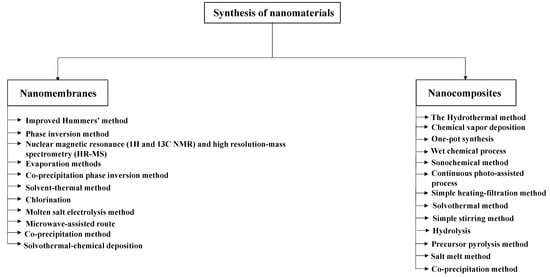
Figure 1 shows the most common methods used in the synthesis of nanomaterials.
Figure 1. The most common methods used in the synthesis of nanomaterials.
2. Nanomembranes
Synthesis and characterization of nanomembranes have received wide attention since the 18th century [
118]. During the 18
th century, membranes were under fabrication, functionalization, and modification at the laboratories without any commercial use [
119]. Since 2004, membrane experimental designs have increased and the number of materials available for these experiments has increased [
118]. One of the famous designs was by Jani and colleagues which designed nanoporous anodic aluminium oxide membranes with desired functions, parameters and properties [
120]. Similarly, Mei and colleagues fabricated ultrathin AlN/GaN porous crystalline nanomembranes with different layouts including tubes, spirals, and curved sheets [
121]. The structural, morphological and chemical properties of nanomembranes will be characterizing using analyses such as X-ray diffraction (XRD), scanning electron microscope (SEM), thermal electron microscope (TEM) and X-ray photoelectron spectroscopy (XPS), Raman spectroscopy, etc. [
122]. The optical and electrical properties of the nanomembranes also will be analysed using UV-Vis diffuse reflectance spectroscopy (UV-Vis DRS) [
123]. “Nanomembranes are synthetic structures with a thickness less than 100 nm and the aspect of surface-area-volume ratio increases to at least a few orders of magnitude” [
124]. Nanomembranes can be classified based on surface chemistry, bulk structure, morphology, and production method [
119]. Nanomembranes have been widely used in many applications such as water and wastewater treatment [
125], biomedical applications [
126], and smart energy storage devices [
127]. In this section, researchers demonstrate the most common methods used in the synthesis and simulation of nanomembranes.
2.1. Synthesis of Nanomembranes
Synthesis is a term for producing nanostructured materials including organic, inorganic, and hybrid nanomembranes [
128]. It exploits the special physicochemical properties of ionic fluids to control transit and growth [
129]. Many methods have been used for the synthesis of nanomembranes such as modified Hummers’ method [
130], solvothermal method [
131], and solvothermal chemical deposition [
132]. Modified Hummers’ method is one of the most common methods used for the synthesis of nanomembranes such as graphene oxide (GO) [
133]. It was developed in 1958 with many advantages such as being safer, faster, and a more efficient method for producing graphite oxide [
134]. The chemical method can generate graphite oxide through the addition of potassium permanganate to a solution of graphite, sodium nitrate, and sulfuric acid [
129]. However, for the synthesis of other nanomembranes such as molybdenum disulphide, the microwave-assisted route has been used [
135]. The microwave-assisted route is “a unique and simple technique for fast and efficient processing of materials with higher reproducibility” [
136]. It has drawn attention due to its homogeneous heating, fast kinetics, high phase purity, and high yield rate of products in relatively short time [
136].
Table 1 shows nanomembranes synthesized by different synthesis methods.
Table 1. Nanomembranes synthesized by different synthesis methods.
| Membrane |
Material Type |
Synthesis Method |
Reference |
|
SWCNTs
|
Carbon nanotube (CNT)
|
Obtained from Cheap Tubes, Inc.
|
[137]
|
|
Graphene oxide
|
Oxidized graphene oxide
|
Obtained commercially from Sigma Aldrich
|
[113]
|
|
ZnO surface
|
Zinc oxide (ZnO)
|
Evaporation methods
|
[138]
|
|
MnFe2O4 nanocubes
|
Manganese ferrite nanoparticles (MnFe2O4)
|
Co-precipitation phase inversion method
|
[139]
|
|
Graphene
|
3D foam graphene
|
Obtained commercially
|
[140]
|
|
MGOA
|
Graphene oxide (GO), ammonium (NH4+)
|
Modified Hummers’ method
|
[141]
|
|
PyTTA-Dva-COF
|
Nitrogen (N), covalent organic framework
|
Solvent-thermal method
|
[142]
|
|
Ultrafiltration PSF/GO membrane
|
Graphene oxide (GO), polysulfone (PSF)
|
Phase inversion method
|
[143]
|
|
Nitrogen doped carbon (CNs)
|
Carbon (C), nitrogen (N), titanium (Ti)
|
Chlorination
|
[144]
|
|
Graphene oxide
|
Graphene oxide
|
Improved Hummers’ method
|
[145]
|
|
Single-layer graphene nanosheets
|
Graphite
|
Solution-phase exfoliation integrating bath sonication and microwave irradiation in organic solvents
|
[146]
|
|
Carbon nanotubes (CNTs)
|
Carbon nanotube (CNT)
|
Nuclear magnetic resonance (1H and 13C NMR) and high resolution-mass spectrometry (HR-MS)
|
[147]
|
|
Graphene oxide
|
Graphene oxide
|
Modified Hummers’ method
|
[148]
|
|
Graphene oxide
|
Graphene oxide
|
Modified Hummers’ method
|
[149]
|
|
MoS2 nanosheets
|
Molybdenum disulphide
|
Molten salt electrolysis method
|
[150]
|
|
MoS2 nanosheets
|
Molybdenum disulphide
|
Microwave-assisted route
|
[151]
|
|
Zn–Fe LDH
|
Zinc (Zn), iron (Fe)
|
Co-precipitation method
|
[152]
|
|
Lanthanum-aluminium perovskite (La2Al4O9)
|
Lanthanum (La), aluminium (Al)
|
Obtained commercially from Aladdin company
|
[153]
|
|
CF/BiOBr/Ag3PO4 cloth
|
Carbon fibre (CF), bismuth oxybromide (BiOBr), silver phosphate (Ag3PO4)
|
Solvothermal-chemical deposition
|
[154]
|
As shown in Table 1, 11 types of nanomembranes have been synthesized by using different materials. Graphene and graphene oxide (GO) were the most synthesized nanomembranes by using Hummers’ method because of their widespread use in water and wastewater treatment. However, other nanocomposites such as nitrogen doped carbon (CNs), are synthesized by using chlorination of Ti(C0.7N0.3) at various temperatures resulting in well-developed micro-pores and small meso-pores with uniform pore structures.
2.2. Simulation of Nanomembranes
Density functional theory (DFT) is a computational simulation method used in chemistry, physics, and materials science for the calculation of the mechanical and electronic properties of atoms and molecules [
155]. There are many simulation software used for DFT calculations such as Material Studio, Vienna Ab initio Simulation Package (VASP), and GAMESS, etc. The simulation software have been used by researchers and engineers to improve the performance of materials in many applications including pharmaceuticals, catalysts, polymers and composites, metals and alloys, batteries and fuel cells [
156]. They have many advantages such as developing new cost-effective materials with better performance and more efficiently than with test and experimentation alone [
157]. Material studio is a three-dimensional (3D) modelling and simulation software developed and distributed by BIOVIA to allow researchers in material science and chemistry to understand the behaviour and relationships of a material’s atomic and molecular structure [
156]. Similarly, VASP, Gaussian 09, and GAMESS have been used for atomic scale materials modelling using DFT with different functional groups including (B3LYP) and different methods such as the projector augmented wave method (PAW), and Perdew-Burke-Ernzerhof (PBE) method [
158]. PAW and PBE methods are both efficient for the electronic structure calculations of large systems [
159]. Furthermore, they are used to improve the accuracy of the electrical and electronic calculations for magnetic materials, alkali and alkali earth elements [
160].
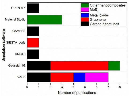
Figure 2 shows simulation software used to produce nanomembranes with the number of publications using each software.
Figure 2. Simulation software used to produce nanomembranes with the number of publications by each software.
As shown in
Figure 4, Gaussian 09 and VASP contributed to the simulation of 15 nanomembranes out of 22 nanomembranes in this review paper. 8 of the 15 nanomembranes were graphene or graphene oxide (GO). This is due to the high accuracy in the simulation of graphene and GO nanomembranes by these simulation software as indicated in previous studies [
161,
162]. In addition, molybdenum disulphide (MoS
2) nanosheet has been simulated by using VASP with PAW simulation method, while other nanocomposites such as Zn–Fe LDH, and (CF/BiOBr/Ag
3PO
4) cloth, have been simulated by using Material Studio with DMol3 and GGA-PBE codes, respectively.
Table 2 shows the simulation software and methods used for simulation of nanomembranes.
Table 2. Nanomembranes simulated by different simulation software.
| Membrane |
Software |
Simulation Method |
Mathematical Model |
Reference |
| (O-CNTs), (G-CNTs) |
Gaussian 09W |
DFT (B3LYP functional group) |
Integral Equation Formalism Polarized Continuum Model (IEFPCM) |
[163] |
| Graphene |
VASP |
DFT (PAW) |
Kohn-Sham equations |
[140] |
| Graphene oxide |
SIESTA code |
DFT (LDA) |
Kohn-Sham equations |
[113] |
| MGOA |
Gaussian 09 |
DFT (B3LYP functional group) |
Thomas, Yoon–Nelson, and Adams–Bohart models |
[141] |
| PyTTA-Dva-COF |
Gaussian 09 |
DFT (B3LYP functional group) |
ONIOM model |
[142] |
| Vertically aligned (VA) CNT (open-end) hybrid membrane |
DMOL3 package |
DFT (PW91) |
Exchange-Correlation functional |
[164] |
| Ultrafiltration PSF/GO membrane |
OPEN-MX software |
DFT (LDA) |
Hoffmann’s model |
[143] |
| Graphene oxide |
Gaussian 09 |
DFT (Gaussian-Lorentzian function) |
Exchange-Correlation functional |
[145] |
| S, N co-doped graphene aerogel (SN-rGO-A) |
Gaussian 09 |
DFT (B3LYP functional group) |
Thomas, Yoon–Nelson, and Adams–Bohart models |
[165] |
| ZIF8@carbon nanotube |
VASP |
DFT (PBE) |
Exchange-Correlation functional |
[166] |
| Carbonaceous nanofiber/Ni-Al layered double hydroxide (CNF/LDH) |
VASP |
DFT (PAW) |
Kohn-Sham equations |
[167] |
| SWCNTs, MWCNTs, and PAC |
GAMESS |
DFT (B3LYP5 functional) |
Exchange-Correlation functional |
[168] |
| Single-layer graphene nanosheets |
VASP |
DFT (PAW) |
Kohn-Sham equations |
[146] |
| Graphene oxide |
Gaussian 09 |
DFT (PBE1PBE functional model) |
Exchange-Correlation functional |
[148] |
| Graphene oxide |
Gaussian 09 |
DFT (B3LYP/6-31G* level) |
Exchange-Correlation functional |
[149] |
| ZnO surface |
VASP |
DFT (PBE) |
Exchange-Correlation functional |
[138] |
| MoS2 nanosheets |
VASP |
DFT (PAW) |
Kohn-Sham equations |
[150] |
| Zn–Fe LDH |
Materials Studio (BIOVIA, 2017) |
DFT (DMol3) code |
Exchange-Correlation functional |
[152] |
| Lanthanum-aluminium perovskite (La2Al4O9) |
Materials Studio |
DFT (PBE) |
Exchange-Correlation functional |
[153] |
| MoS2 nanosheets |
VASP |
DFT (PAW) |
Kohn-Sham equations |
[151] |
| SWCNTs |
Gaussview |
DFT (B3LYP5) functional |
Exchange-Correlation functional |
[137] |
| CF/BiOBr/Ag3PO4 cloth |
Materials Studio |
DFT (GGA-PBE) |
Exchange-Correlation functional |
[154] |
As shown in
Table 2, PAW, PBE, and B3LYP are the most common methods used for the DFT calculations of nanomembranes. These calculations are performed based on the solution of Kohn-Sham equations by PAW method. On the other hand, the exchange-correlation functional model, and the Thomas, Yoon–Nelson, and Adams–Bohart model have been solved by B3LYP and PBE method, respectively. Along the same lines, these methods (PAW, PBE, and B3LYP) have been used for the simulation of nanocomposite materials as explained later in
Section 2.2.2.
3. Nanocomposites
Nanocomposite are characterized by their very small size, measured in nanometres [
170]. Nanocomposite materials have attractive properties resulting from the combination of inorganic or organic components at the molecular level [
171,
172]. There are many applications of nanocomposite materials in wastewater treatment [
173], energy storage [
174], drug delivery [
175], and for biomedical purposes [
176]. In wastewater treatment, nanocomposite materials have been widely used to treat surface water, sewage, and ground water [
177]. By 2009, nano-processing technologies were documented at 44 cleaning sites around the world, most of them in the United States [
178]. The synthesis of these nanocomposites received wide attention by the researchers in the last decade [
179]. In this section, researchers demonstrate the most common methods used in the synthesis of nanocomposite materials.
2.1. Synthesis of Nanocomposites
For synthesis and characterization of these nanomaterials, many methods have been used including the hydrothermal method [
180], chemical vapor deposition (CVD) [
181], and one-pot synthesis [
182]. The hydrothermal method is one of the most common methods used in the synthesis of nanocomposites [
180].
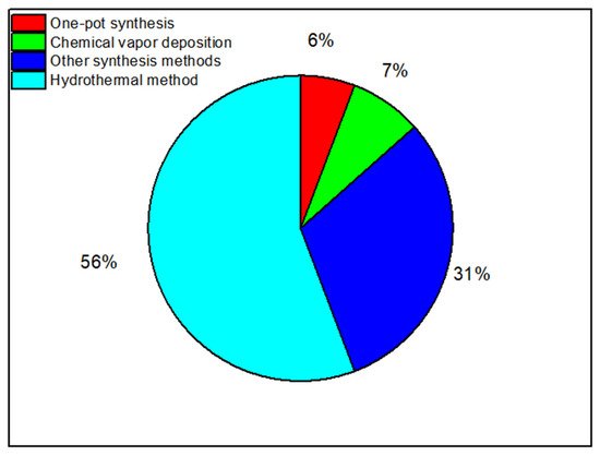
Figure 5 shows the percentages of the number of publications reviewed in this review paper by each experimental method. As shows in
Figure 3, the hydrothermal method has been used in more than 56% of the publications reviewed.
Figure 3. The percentages of the number of publications by each experimental method used in the synthesis of nanocomposite materials.
The Hydrothermal Method
Hydrothermal synthesis is a method that uses very high temperatures ranging from room temperature to much higher temperatures to synthesize nanomaterials [
183]. It was given the name “hydrothermal” because water is used as the solvent [
184]. The hydrothermal method was first discovered in the 19th century [
185]. It has been widely used by researchers and the first publication on this method appeared in 1813 [
185]. The publication was about “Synthesis and Characterization of Zinc Tin Sulphide (ZTS) Thin Films via Chemical Bath Deposition Route” [
185]. Hydrothermal synthesis has many advantages over other synthesis methods including “top down” method, “bottom up” method, and sol-gel method such as being an environmentally friendly, low-cost synthesis method, its simplicity, and the production of high-quality one-dimensional (1D) nanostructures [
186,
187,
188,
189]. However, there are some disadvantages for this method: taking a long time in the production process, corrosion, and difficulty in recycling and regenerating the catalysts [
184,
190]. Recently, hydrothermal synthesis has been used in several applications in science such as food and nutrition, organic chemistry, environmental safety, and energy applications [
191,
192]. For instance, Zhu et al. synthesized a highly efficient heterogeneous Fenton catalyst (CNTs/Fh) for the degradation of (bisphenol A) by using a hydrothermal method [
116]. Similarly, Wang et al. synthesized a pyridinic-N doped graphene/BiVO
4 nanocomposite (N-rGO/BiVO
4) by hydrothermal method with a great potential for the removal of pollutants from wastewater [
193].
Table 3 shows the nanocomposite materials synthesized by the hydrothermal method in the last decade.
Table 3. Nanocomposite materials synthesized by the hydrothermal method.
| Nanocomposite Material |
Material Type |
Reference |
| Heterogeneous Fenton catalysts (CNTs/Fh) |
Oxidized carbon nanotubes (CNTs), ferrihydrite (Fh) |
[116] |
| (N-rGO/BiVO4) |
Bismuth vanadate (BiVO4), reduced graphene oxide (rGO), nitrogen (N) |
[193] |
| ZnO@C |
Zinc Oxide (ZnO), carbon (C) |
[194] |
| Cerium zirconium oxide (CexZryO2) |
Cerium (Ce), zirconium oxide (ZrO2) |
[195] |
| ZnO/Al2O3 |
Zinc oxide (ZnO), aluminium oxide (Al2O3). |
[196] |
| C, N, F/TiO2NTs |
Carbon (C), nitrogen (N), fluoride (F), titanium dioxide nanotubes (TiO2NTs) |
[197] |
| iN-Ti3C2/TiO2 hybrid |
Titanium carbide (Ti3C2), titanium dioxide (TiO2), isopropyl amine, nitrogen (N) |
[198] |
TiO2 nanoflowers
(TNFs) |
Titanium dioxide (TiO2) |
[199] |
| Titanate nanotubes supported TiO2 (TiO2/TiNTs) |
Titanium dioxide (TiO2), titanate nanotubes |
[200] |
Black phosphorus quantum dots/Tubular g-C3N4
(BPQDs/TCN) |
Black phosphorus (BP), tubular g-C3N4 |
[201] |
| Sodium titanate nanotubes (Na-TNT) |
Sodium (Na), titanate nanotubes (TNT) |
[202] |
| Fe2O3-PC nanohybrids |
Iron oxide (Fe2O3) |
[203] |
| NiO nanobelt |
Nickel oxide (NiO) |
[204] |
| Carbon dots/g-C3N4 (C-CN) heterostructures |
Graphitic Carbon Nitride (g-C3N4) |
[205] |
| AgBr/h-MoO3 |
Silver bromide (AgBr), hexagonal molybdenum oxide (h-MoO3) |
[206] |
| Hybrid catalysts (CN-CGs) |
Coal gangue (CG),
graphitic carbon nitride g-C3N4 (CN) |
[207] |
| N-doped BiVO4 |
Nitrogen (N), bismuth vanadate (BiVO4) |
[208] |
| PPECu thin film electrode |
Copper (Cu), phenylacetylene (PPE) |
[209] |
| FexMo1-xS2 catalysts |
Iron (Fe), Molybdenum disulfide (MoS2) |
[210] |
| P-doped porous g-C3N4 |
Graphitic carbon nitride (g-C3N4), phosphorus (P) |
[211] |
| 1D/2D W18O49/g-C3N4 nanocomposites |
Graphitic carbon nitride
(g-C3N4), oxygen-deficient tungsten oxide (W18O49) |
[212] |
| Oct-Cu2O NCs |
Cuprous oxide (Cu2O) |
[213] |
| g-C3N4 |
Graphitic carbon nitride (g-C3N4) |
[214] |
| ZIF8@carbon nanotube |
Carbon nanotube (CNT), zeolitic imidazole framework-8 (ZIF8) |
[166] |
| CNF/LDH |
Carbonaceous nanofiber (CNF), nickel (Ni), aluminium (Al) |
[167] |
| PVP/MoS2 |
Molybdenum disulphide, polyvinylpyrrolidone |
[215] |
| β-CD/TiO2 |
Titanium dioxide (TiO2), β-cyclodextrin C42H70O35 |
[216] |
| MOF-545 |
Zirconyl chloride octahydrate, Sigma-Aldrich; porphyrin, H4-Tcpp-H2, TCl |
[217] |
As shown in
Table 3, the hydrothermal method has been used in the synthesis of different nanocomposite materials including titanium dioxide (TiO
2) nanoflowers, nanomaterials with carbon nanotubes (CNTs), and metal oxides with carbon. The reason for the wide use of the hydrothermal method is its advantages over others in the ability to create crystalline phases, even those which are not stable at the melting point [
218]. For instance, Zhao and colleagues synthesized TiO
2 nanoflowers (TNFs) using hydrothermal and calcination treatments [
199]. The results showed a strong photocatalytic capability, and satisfactory recycled stability of the TNFs, which enhances their value for practical applications in water purification [
199]. Along the same lines, Cheng et al. synthesized a titanate nanotube supported TiO
2 (TiO
2/TiNTs) using the hydrothermal method [
200]. The results showed that TiO
2/TiNTs significantly eliminated the toxicity of phenanthrene and can greatly decrease the potential risks of phenanthrene to aquatic organisms [
200].
Chemical Vapor Deposition
Chemical vapor deposition (CVD) is a coating process that is defined as a method to produce solids with high purity by using thermally induced chemical reactions at the surface of a heated substrate [
219]. CVD has many applications in medicine [
220], electronic applications [
221], and chemical industries [
222]. It has many advantages over other synthesis methods such as the ability to deposit a wide variety of materials with very high purity [
223]. The CVD method started in the 19th century with the production of lamp filaments. Then, Van Arkel in the 20th century deposited metals from the gas phase for application in the lamp industry [
224,
225]. The CVD method has three different types based on the conditions of the process classified by applied pressure [
226], physical properties of the vapor [
227], and plasma methods [
228]. It has been used in the production of several materials including monocrystalline, polycrystalline, amorphous, preparation of carbon nanotubes (CNTs) and carbon nanofibers [
221,
229]. In addition, CVD is famous for producing semiconductors such as the synthesis of 2D Tungsten disulphide (WS
2) monolayer [
230].
Table 4 shows nanocomposite materials synthesized by the chemical vapor deposition (CVD) method.
Table 4. Nanocomposite materials synthesized by the chemical vapor deposition (CVD) method.
| Nanocomposite Material |
Material Type |
Reference |
| Co3O4/CNTs |
Carbon nanotubes (CNTs), cobalt tetra-oxide (Co3O4) |
[231] |
| O-CNTs, G-CNTs |
Oxidized carbon nanotubes (O-CNTs), graphitized carbon nanotubes (G-CNTs). |
[163] |
| Vertically aligned (VA) CNT (open-end) hybrid membrane |
Carbon nanotube (CNT), polydimethylsiloxane
(PDMS) membrane |
[164] |
| COOH/CNTs |
Carbon nanotubes (CNTs), carboxylic functionalized groups (COOH) |
[232] |
This entry is adapted from the peer-reviewed paper 10.3390/membranes12040360