In the context of energy conservation and the reduction of CO2 emissions, inconsistencies between the inevitable emission of CO2 in traditional hydrogen production methods and eco-friendly targets have become more apparent over time. The catalytic decomposition of methane (CDM) is a novel technology capable of producing hydrogen without releasing CO2. Since hydrogen produced via CDM is neither blue nor green, the term “turquoise” is selected to describe this technology. Notably, the by-products of methane cracking are simply carbon deposits with different structures, which can offset the cost of hydrogen production cost should they be harvested. However, the encapsulation of catalysts by such carbon deposits reduces the contact area between said catalysts and methane throughout the CDM process, thereby rendering the continuous production of hydrogen impossible. This entry mainly covers the CDM reaction mechanisms of the three common metal-based catalysts (Ni, Co, Fe) from experimental and modelling approaches. The by-products of carbon modality and the key parameters that affect the carbon formation mechanisms are also discussed.
1. “Tip Growth” Mechanism
Carbon filaments following the “tip-growth” mechanism are the most common type of carbon deposition observed in the catalytic decomposition of methane (CDM) process, first defined by Reshetenko and his workmates
[1]. According to their opinions, the “tip-growth” mechanism referred to one carbon filament growing from one catalyst particle, while the latter is always located at the top of the filament. Take the Ni-based catalyst in
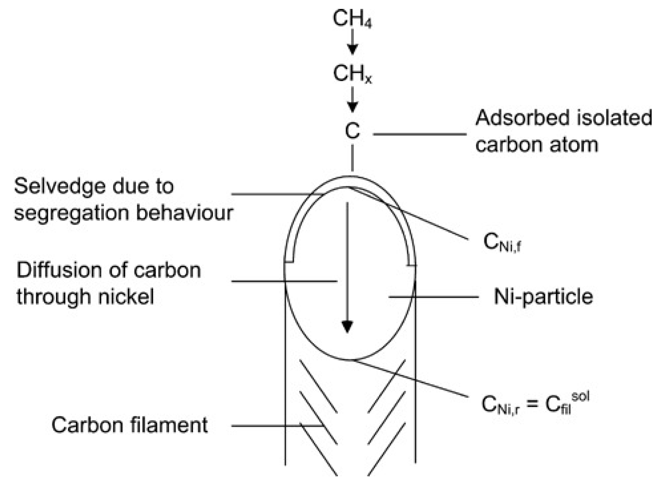
Figure 1 as an example in which the carbon filament grows from the carbon core on the metal-support side. With the continuous stacking of graphite layers, the Ni particle is separated from the support and remains at the tip of the carbon wire to ensure continuous contact with methane. The following section discusses experimental results on Ni, Co, and Fe-based catalysts that conform to this growth mechanism and summarizes the influencing factors for the carbon filament growth.
Figure 1. Schematic diagram of the “tip-growth” mechanism of carbon filament
[2].
Zhang et al. and Shen et al.
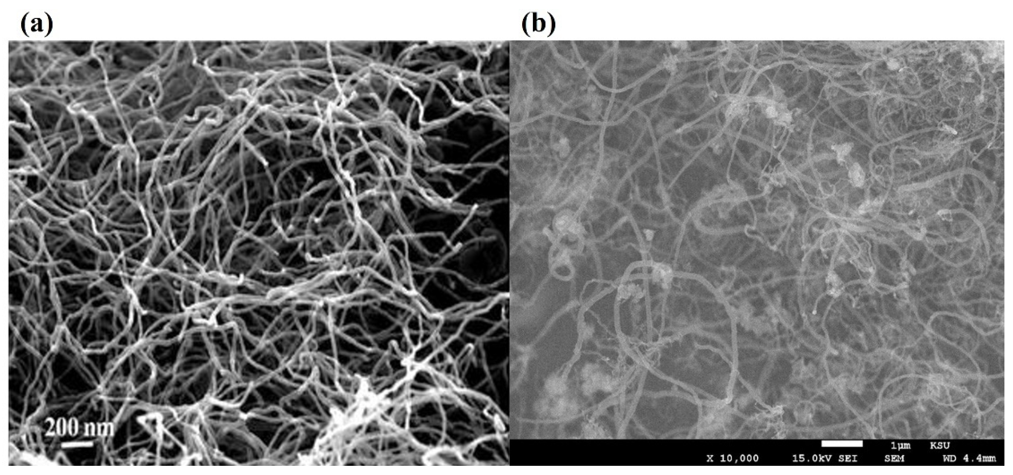
[3][4] captured carbon filament images on the deactivated Ni-based catalysts by SEM/TEM and proved their catalyst samples followed the “tip-growth” mechanism. Bright spots at the tip of these cross-growing carbon filaments were deactivated Ni metal particles due to carbon encapsulation, proved by EDS element identification (
Figure 2a). Takenaka et al.
[5][6] observed similar bright metal tips in carbon filaments from CDM experiments using Co and Fe-based catalysts (
Figure 2b). They pointed out that the “tip-growth” mechanism would extend the catalyst lifetime and increase the hydrogen yield of fresh samples, but catalysts would lose their activity after the regeneration cycle. Although metal particles fell back to the supporting phase after the carbon removal process, it still led to irreversible damage to the catalyst structure.
Figure 2. (
a) FESEM image of carbon fibers deposited over Ni/SiO2
[7]; (
b) FESEM image of carbon fibers formed over Fe/Al2O3
[8].
Catalysts used for methane cracking usually consist of active metals and support materials. The active metal phase has more intuitive effects on the outcome because its type and loading ratio determines the number of active sites available. From CDM experiments conducted at 550 °C and atmospheric pressure, Avdeeva et al.
[9] observed carbon filaments with Ni metal particles at the tip from highly loaded Ni/Al2O3 catalysts by TEM. Among them, the 90% Ni/Al2O3 sample obtained the highest carbon yield, equal to 145 gC/gNi. Therefore, they believed catalysts with a higher metal ratio provided more active sites in the reaction, which had better performance. However, the supporting phase is indispensable because the pure Ni particles without supports were quickly encapsulated by carbons and deactivated. Reshetenko and his co-workers also support these results
[1][10]. With the same catalyst and operation conditions, they produced 111.1 gC/gNi carbon filaments that followed the “tip-growth” mechanism. As for Ni/Al2O3 with a low metal proportion, Li et al.
[11] found that the surface particle distribution and activity can be improved by changing the preparation method. Based on the experimental results, the 12% Ni/Al2O3 sample produced 132 gC/gNi carbon depositions at 500 °C in the fixed bed reactor.
Except for different metal-loaded ratios, the supporting materials also affect the carbon filament growth through interphase interaction. Some experimental results revealed that Al2O3 is not the most suitable supporting material for Ni-based catalysts because the NiAl2O4 compound may form at high temperatures. This solid solution is difficult to reduce by hydrogen and limits the number of active sites. By comparing the cracking performance of 12% Ni loaded on Al2O3 and SiO2, Li et al.
[11] pointed out that samples with SiO2 support obtained higher carbon and hydrogen yield under the same operating conditions. When the metal proportions were reduced to 5%, defects from solid solutions became more obvious. Correspondingly, Ermakova et al.
[12] extracted 340 gC/gNi carbons from a 90% Ni/SiO2 catalyst sample in methane cracking experiments operated between 300–700 °C. Compared with Al2O3, SiO2 supports can bring better stability to the catalyst, which extends the lifetime of samples nearly three times under the same conditions. After realizing the good compatibility of Ni and SiO2, researchers represented by Takenaka
[13][14] prepared Ni/SiO2 catalysts with different loading ratios to find the sample with the best catalytic activity. At 500 °C and a 60 mL/min pure methane flow rate, a 40% Ni/SiO2 catalyst showed the highest carbon yield (491 gC/gNi) and the longest lifetime (~70 h), which became the record at that time.
The CDM experiments on Co-based and Fe-based catalysts also produce carbon filaments conformed to the “tip-growth” mechanism. Avdeeva et al.
[15] prepared 50–75 wt.% Co/Al2O3 samples and tested their catalytic activities between 475–600 °C. The optimal sample (75% Co-loaded) remained active for 15 h at 500 °C and produced 63 gC/gCo hollow carbon filaments. Although its yield was lower than Ni-based catalysts, more CNTs were observed in carbon by-products. These results are mostly consistent with Takenaka’s group
[6]. They reported the performance of low-loaded Co catalysts in the CDM process between 500–800 °C and found the best sample produced 56.04 gC/gCo hollow carbon filaments. As for the supporting material in Co-based catalysts, Ashik and Daud
[16] believed Al2O3 may be the most suitable. Under the same operating conditions, Co/SiO2 and Co/MgO samples had evident agglomeration issues. From the TEM images, most of the particles were tens of times larger than expected, which significantly reduced the specific surface area and caused samples rapidly deactivated.
Due to the special reaction mechanism, Fe-based catalysts show methane cracking after the temperature exceeds the activation threshold. Zhou et al.
[17] first tested the performance of high-loaded Fe/Al2O3 catalysts in the CDM process and found the best sample showed a stable conversion rate in 10 h. On this basis, Anis et al.
[8] reported the catalytic activity of the 20% Fe/Al2O3 sample at 800 °C. Within the first two hours of cracking it maintained the methane conversion rate between 80–85%. However, excessive carbon depositions plugged the reactor and led to a high backup pressure, which stopped the reaction. The choice of supporting materials of Fe-based catalysts was mentioned by Ermakova et al.
[18] under the same loading ratio and reaction conditions. Their results proved that the adaptability of ZrO2, Al2O3, and TiO2 with Fe was not as good as SiO2. After optimization, the best Fe/SiO2 sample produced about 45 gC/gFe, which was mainly composed of thin-wall carbon nanotubes.
2. “Base Growth” Mechanism
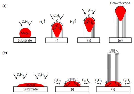
Although most catalysts conform to the tip growth mechanism during the catalytic decomposition of methane (CDM) reaction, there are still some exceptions. When the interaction between phases is strong enough, the graphite layers stacking on the metal-support side fail to push the metal particle up. In this situation, the “base growth” mechanism shown in
Figure 3b occurs, and carbon filaments are forced to grow from the metal-gas side
[19]. Nevertheless, this mechanism results in the active sites on the surface quickly becoming covered by carbon deposits, thus reducing the effective lifetime of catalysts.
Figure 3. (
a) Carbon filaments followed the “tip growth” mechanism, in which catalyst is enclosed at the tip of the carbon filament; (
b) Carbon filaments followed the “base growth” mechanism, in which catalyst remains at the bottom of the growing carbon
[19].
Most catalysts that follow the “base growth” mechanism are Co-based and produce hollow/solid seamless graphite cylinder carbon filaments. Frusteri et al.
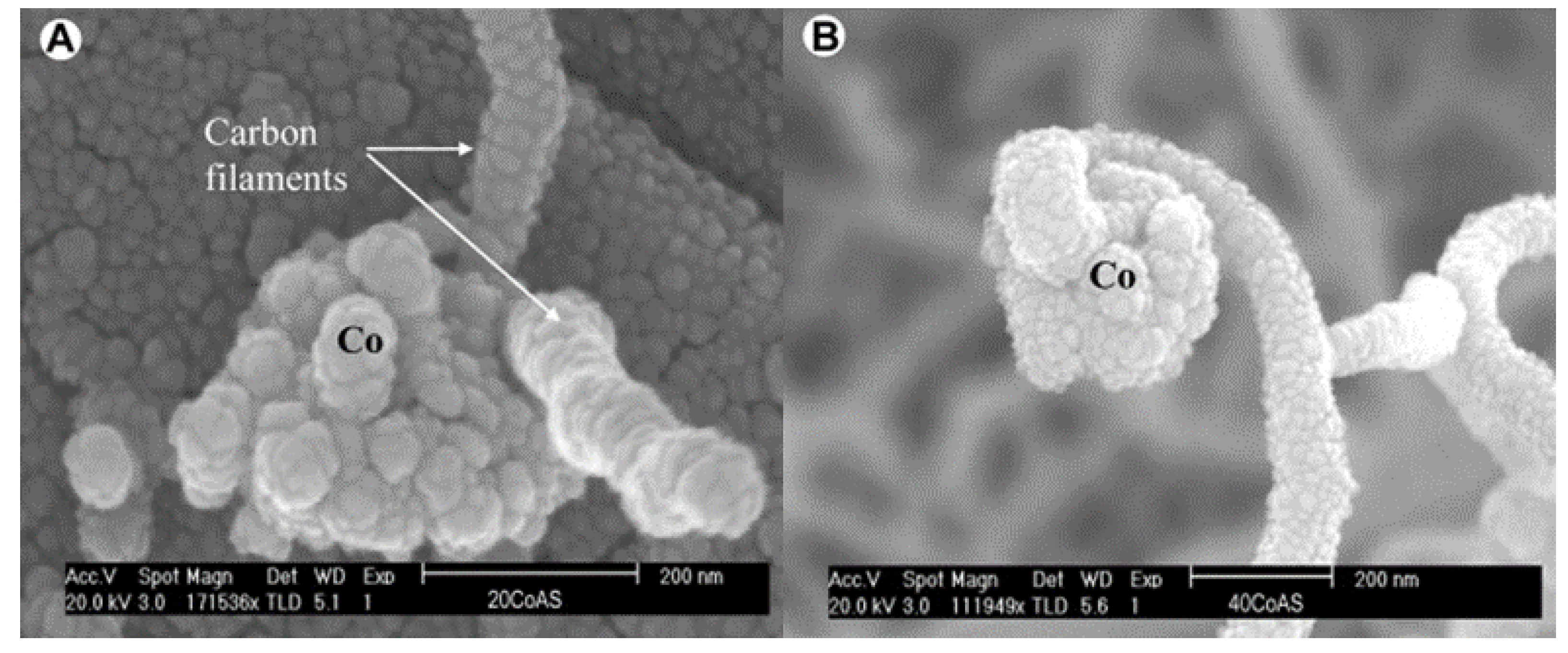
[20] verified this mechanism by methane cracking experiments on Co/Al2O3 samples with different loading ratios at 650 °C. Based on the carbon filament structure captured by SEM, they found that the growth mechanism on Co-based catalysts was closely related to the metal proportion. As shown in
Figure 4a, carbon filaments on low-loaded Co samples (≤20%) were extended from the metal-gas side in multiple directions. By contrast, for high-loaded Co samples (≥40%), the growth of carbon filaments obeyed the “tip-growth” mechanism, as shown in
Figure 4b. G.I.Talinao et al.
[21] further revealed the fundamental reasons for the growth mechanism change. After temperature-programmed reduction (TPR) analysis, a large amount of Co3O4 was detected on the high-loaded Co-based catalysts. This caused low metallic dispersion and weak phase interactions. On the samples with low Co loading, the content of Co3O4 was reduced, and more metallic cobalt particles were formed, which produced better dispersion of the active metal phase and stronger interactions
[22].
Figure 4. (
A) SEM image of the “base growth” mechanism for low-loaded Co-based catalyst. (
B) SEM image “tip growth” mechanism for high-loaded Co-based catalyst
[20].
Takenaka et al.
[6] prepared 20% Co/Al2O3 samples by the impregnation method and captured the carbon filaments that followed the “base growth” mechanism in CDM reactions operated between 600–800 °C. They further designed comparative experiments to summarize the pros and cons of two carbon filament growth mechanisms. The activity of fresh and regenerated Co-based samples was compared with 20% Ni/Al2O3 catalysts prepared under the same conditions. Fresh sample results showed that the Ni-based sample with the “tip-growth” mechanism had several times more hydrogen than Co-based catalysts with a prolonged lifespan. However, after several air oxidative regeneration cycles, the Ni-based catalyst activity decreased significantly with the number of regenerations cycles. This was due to the destruction of the catalyst structure brought by the carbon oxidation and elimination process. Co-based samples that conform to the “base growth” mechanism avoided this problem since the carbon deposits were easily removed without damaged catalyst structures. Therefore, the “base growth” mechanism is more suitable for the large-scale CDM process, which allows catalysts to maintain a stable methane conversion rate through multiple regeneration cycles to achieve continued hydrogen generation
[21].
This entry is adapted from the peer-reviewed paper 10.3390/en15072573